Chapter V · MAKING FUSE PARTS
Reading edition
Combination timing and percussion fuses comprise a large number of small parts made from different metals and alloys, and are produced in various ways. Some of the parts are made from brass rod or alloys of copper and aluminum, whereas others are made from hot-pressed forgings and are machined after being formed to shape. In the following, a brief description of several different methods of making the most important fuse parts will be illustrated and described, together with details regarding the forging tools used for the socket and plug.
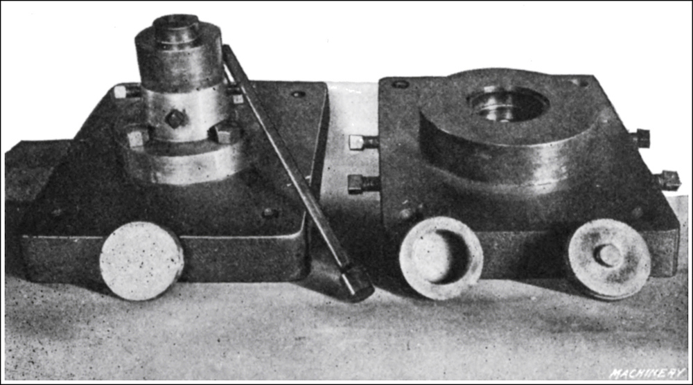
Fig. 1. Tools used in forging Brass Fuse Socket
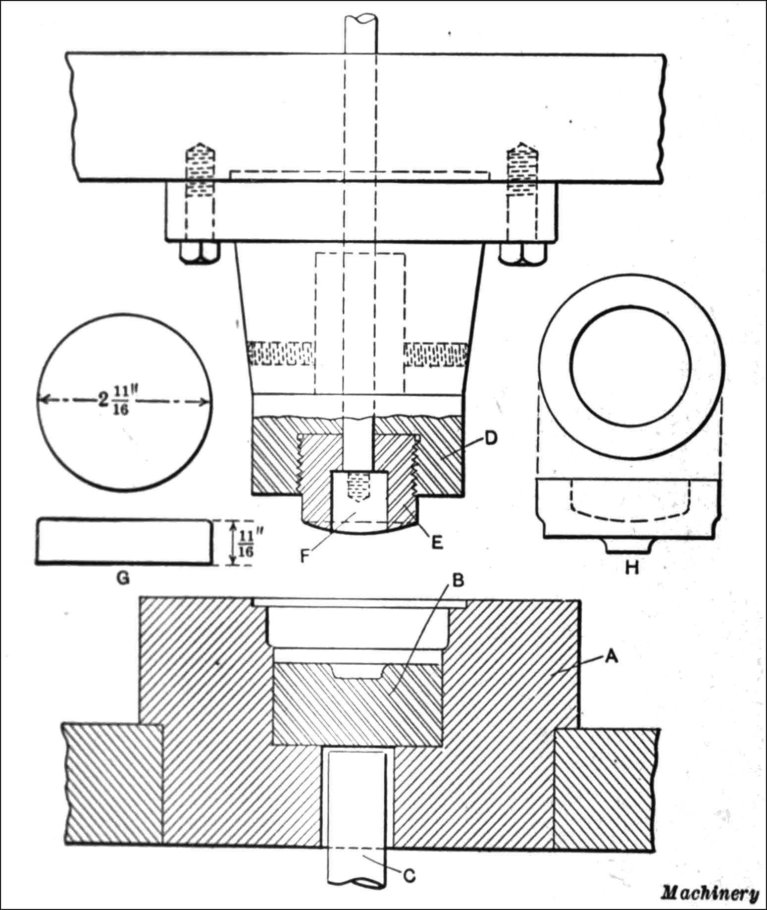
Fig. 2. Diagram showing Construction of Tools used in forging Fuse Socket
Forging the Fuse Socket.—The fuse socket, which screws into the nose of the shrapnel shell and acts as a base for the fuse, is made from a special forgeable alloy casting containing 40 per cent copper, 58 per cent zinc, and 2 per cent lead. The first step in this process is to melt the above constituents in the usual manner and then to cast the slugs in sand molds, six to eight being gated together. These castings are made 2¹¹⁄₁₆ inches in diameter by ¹¹⁄₁₆ inch thick, as shown in Figs. 1 and 2. There are several methods in use for forging the plugs, but the general principle is the same. In this particular case, a No. 23 Bliss press capable of exerting a pressure of 250 tons is used. The castings are placed in the furnace where they are allowed to “soak” at a temperature varying from 1200 to 1300 degrees F., or, in other words, until they reach a dull red color. One casting at a time is then quickly removed and placed in the impression of the die shown to the right in Fig. 1 and in detail in Fig. 2. The working parts of these dies are made from Jessop’s high-carbon tool steel and one blow of the press completes the forging, turning out about 3000 in ten hours. The tools used for this purpose are of interesting construction, as shown in Fig. 2. They comprise a lower die A machined out to the shape of the finished forging and carrying an ejector, and lower former B operated by plunger C which ejects the forging if it sticks in the die. The top member or punch comprises a holder D into which the punch E is screwed. This is bored out to fit an ejector F which ejects the forging as the ram of the press ascends. Punch E and stripper or ejector F are made from high-speed steel, hardened. G shows the cast blank and H the completed forging.
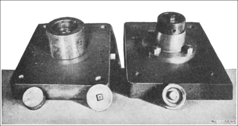
Fig. 3. Tools used for forging Brass Plug
Forging Brass Plugs.—The brass plug shown in Fig. 3 is used as a temporary cap for the shrapnel to protect it during transportation. It remains in the fuse socket until the shrapnel shell reaches the field of operations, when it is removed and replaced by the timing fuse. This member is made from a special forgeable alloy casting 2 inches in diameter by ⁷⁄₈ inch thick and is cast in sand molds in a similar manner to the fuse socket. It is also composed of the same constituents as the socket and is forged in the same type of press. The construction of the tools, however, varies somewhat from that of the tools used in making the socket, as will be seen upon reference to Figs. 3 and 4. The tools for the plug comprise a lower die A carrying a combined ejector and forming die B. Inserted in this lower forming die is a secondary ejector C which is operated by plunger D. The upper member of this forging tool consists of a punch-holder E carrying forming punch F which is counterbored to receive an ejector ring G. Passing down through the center of punch F is a center-punch H that is made in two parts. The lower member is made of high-speed steel, hardened, whereas the upper portion is ordinary carbon steel. This center-punch is operated to eject the forging by a plunger I on the up-stroke of the press through the action of three pins J coming in contact with the flange on punch H. K shows the rough casting and L the completed forging.
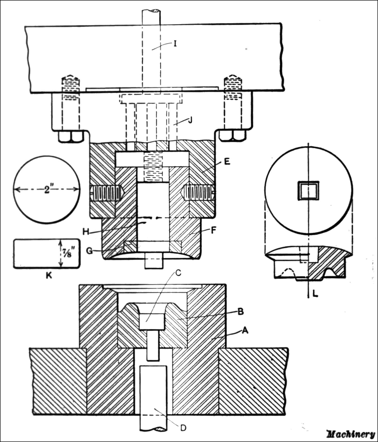
Fig. 4. Diagram showing Construction of Tools for forging Brass Plug
Tooling for Machining Brass Socket.—The New Britain automatic chucking machine, referred to in the following, consists essentially of a multiple-chuck turret with capacity for holding five or six pieces of work, acted upon simultaneously by four or five tool-holding spindles. The sequence of operations is similar to that of a multiple-spindle screw machine. A finished piece is removed and a rough blank inserted at each indexing. The machine is not idle while chucking, there being one more chuck than spindles.
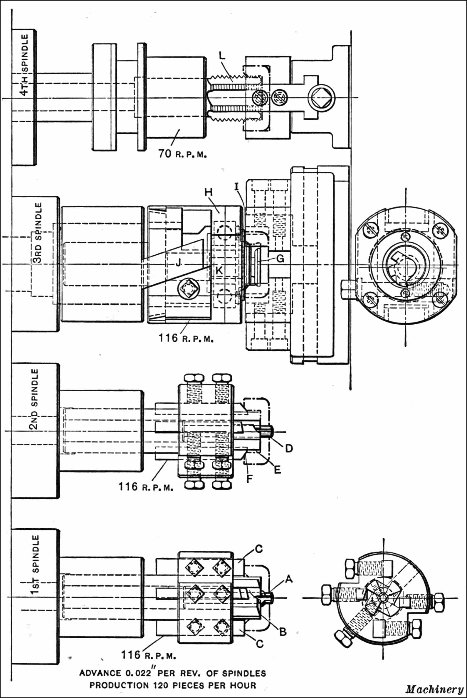
Fig. 5. Diagram showing First Series of Operations on Fuse Socket on the New Britain Automatic Chucking Machine
The shrapnel socket which, as previously explained, is made from a brass casting and pressed into rough shape, is machined in two settings in the New Britain No. 24 chucking machine. This machine has four spindles, and at the first spindle position, as shown in Fig. 5, reamer A cleans out the hole in the pressed brass blank, counterbore B cleans out the inside, and tool C faces the end. At the second spindle position, reamer D finishes the central hole, counterbore E faces the bottom, and tool F chamfers the hole.
The under-cutting preparatory to threading is done at the third spindle position. The operation is performed with tool G working on the cross-cutting head H. When the pressed blank is fed in and reaches stop I, it commences to push the housing H of the cross-cutting head backward. A pair of stationary fingers J operate in oblique slots in the housing H, and as the housing presses down on these fingers, the motion gives a cross movement to the under-cutting tool G and its arbor K. In this manner, the under-cutting of the piece is performed. The fourth spindle operation is simply that of tapping the threaded interior with a tap L.
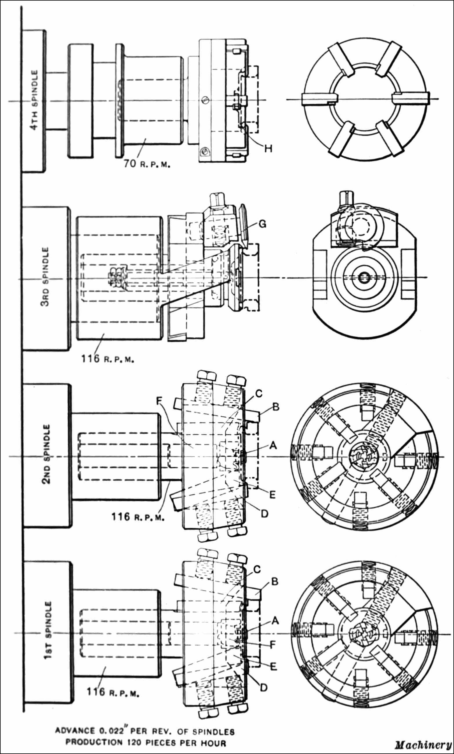
Fig. 6. Diagram Illustrating Second Series of Operations on Fuse Socket on New Britain Automatic Chucking Machine
Second Operation on Shrapnel Socket.—Fig. 6 shows the order of operations performed on the shrapnel socket at the second chucking, the work being screwed on threaded arbors. At the first spindle position, pilot A engages the central hole, while tool B turns the external diameter, tool C chamfers the corner, tool D turns the thread diameter, tool E faces the shoulder, and counterbore F finish-forms the nose of the piece. At the second position, these same surfaces are machined with finishing tools of the same design as those just described.
At the third spindle position, the shoulder at the end of the threaded section is under-cut. This is done by a cross-cutting head, similar to that shown in Fig. 5 and carrying the cutter G. At the fourth spindle position, the final operation—threading—is performed with die H.
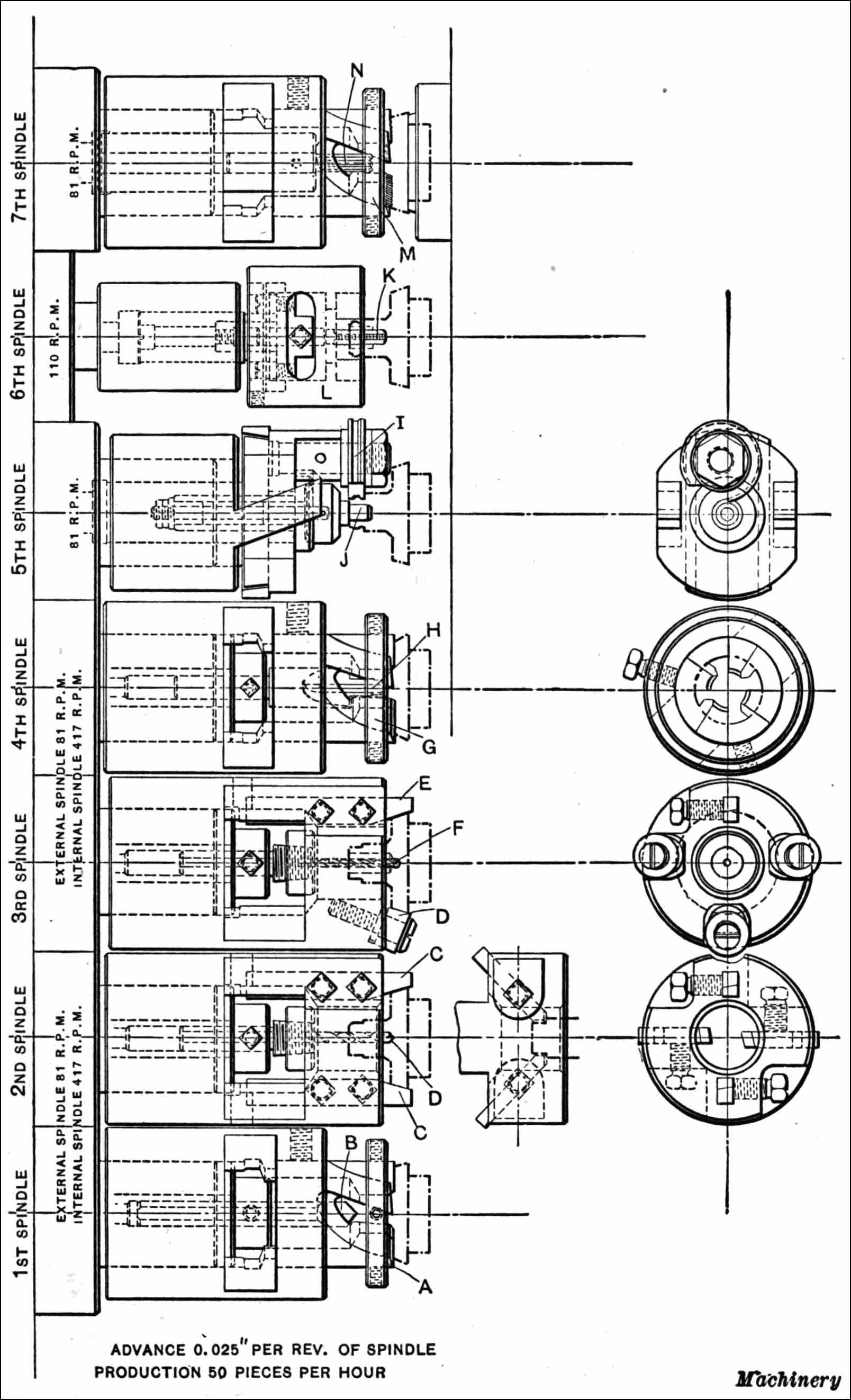
Fig. 7. First Series of Operations on Fuse Body on No. 73 Seven-spindle New Britain Automatic Chucking Machine
Machining Fuse Bodies.—In Fig. 7 is illustrated an interesting tooling set-up for machining a fuse body. This is done on the No. 73 seven-spindle New Britain automatic chucking machine. The operations in this set-up are performed on one end only of the fuse body. Strictly speaking, this is a seven-spindle machine, but the first four spindles carry internal spindles running at high speed that co-operate with the external spindles in machining the work, making this virtually an eleven-spindle machine. At the first spindle position, the broad face and stem are machined with cutters A of hollow-mill type, and centering tool B, carried in the inner spindle, centers the work for drilling.
In the second spindle position, tools C bevel the external diameter of the flange at the same time that drill D is producing the hole in the stem. In the third spindle position, roll D supports the work against the thrust of beveling tool E, and the small drill F held in the internal spindle deepens the hole. At the fourth spindle position, the external spindle carries a hollow-mill G that finishes the stem diameter, and a counterbore H is carried in the internal spindle to machine the central hole.
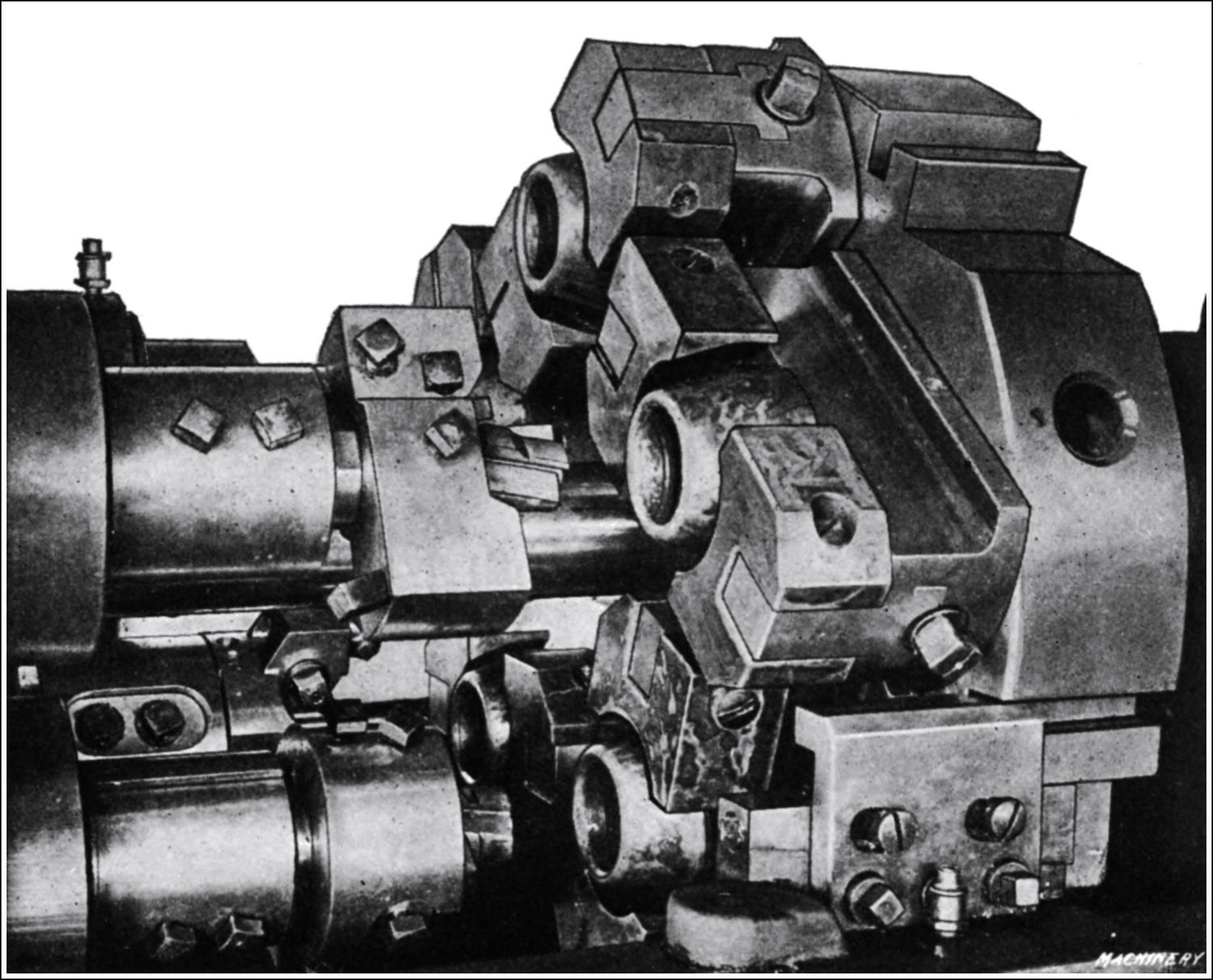
Fig. 8. Machining a Shrapnel Head on the New Britain No. 24 Automatic Chucking Machine
A cross-cutting head in the fifth spindle position carries a circular tool I that machines on both sides of the section subsequently to be threaded, and while this operation is being performed the pilot J steadies the work as well as the tool-holder. In the sixth spindle position, the small hole is threaded with tap K, and the exterior is threaded with a die, tap and die being of different pitches. In the seventh spindle position, a holder carries the forming tool M for cutting grooves in the face of the flange, and the same spindle carries a reamer N that finishes the hole in the stem.
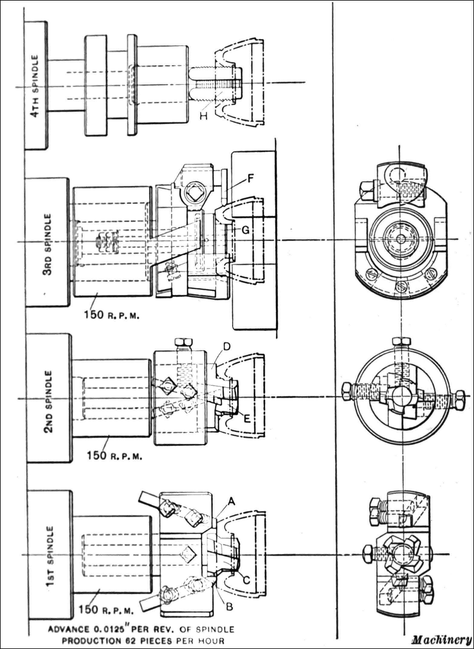
Fig. 9. First Series of Operations on Shrapnel Head on the New Britain Automatic Chucking Machine
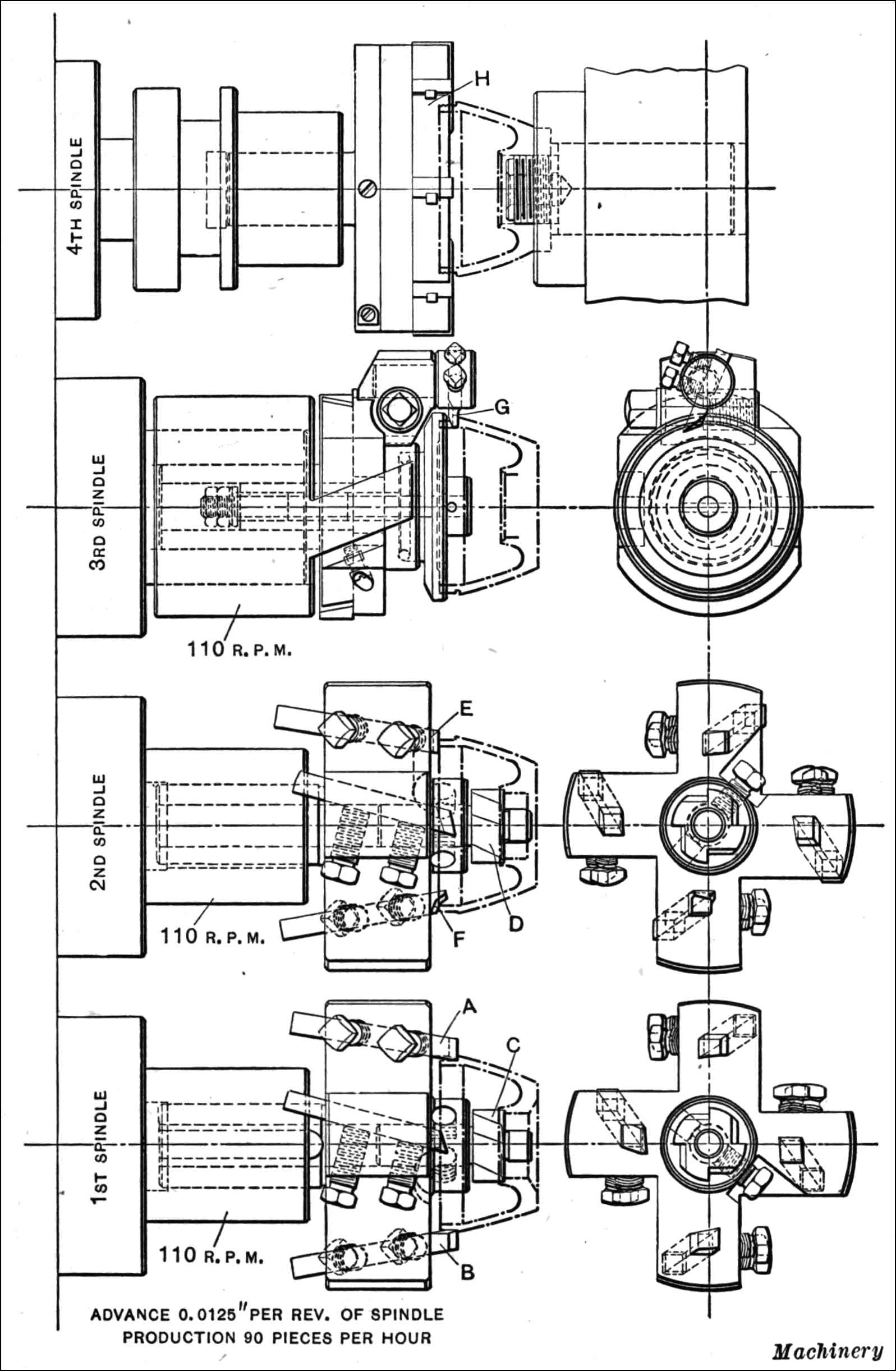
Fig. 10. Second Series of Operations on Shrapnel Head on the New Britain Automatic Chucking Machine
Machining Steel Shrapnel Heads.—Heads for shrapnel shells made from cold-drawn steel stampings are machined in two settings on a No. 24 New Britain automatic chucking machine of the four-spindle type, shown in Fig. 8. This piece, shown in Fig. 9 in its sequence of operations, is especially difficult to machine on account of the stringy nature of the metal. The work is held for the first chucking with the small end out, and in the first spindle position the facing on the end is distributed between tools A and B, while counterbore C roughs out and chamfers the hole. In the second spindle position, tool D faces the end, and counterbore E finishes the hole. A cross-cutting head of a type similar to that previously described is carried in the third spindle position. This retains a tool F which produces an annular groove in the nose of the head, the work being supported with pilot G. The fourth and last operation consists in threading the hole with the tap H.
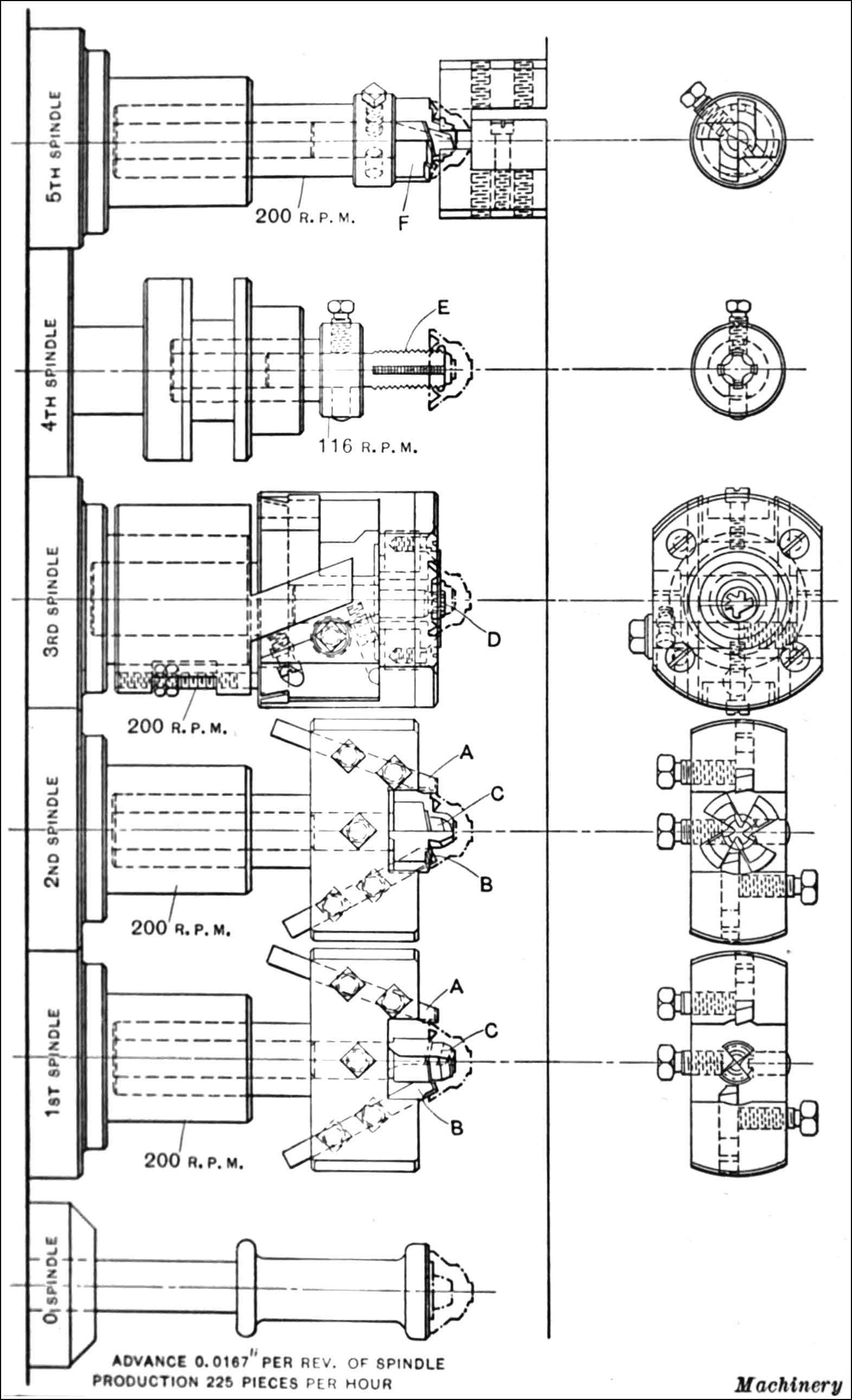
Fig. 11. Diagram showing Tooling Set-up for machining Fuse Nose on New Britain Automatic Chucking Machine
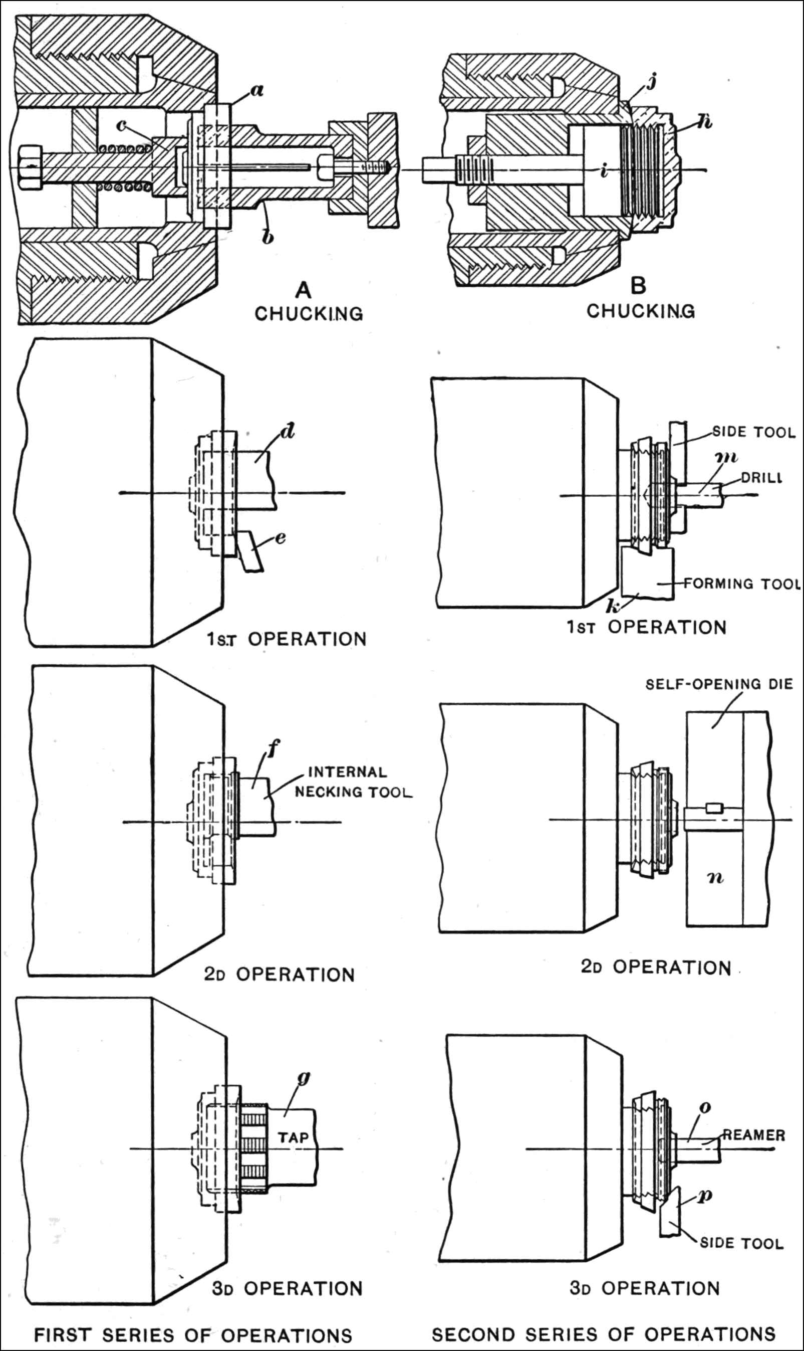
Fig. 12. Machining Brass Fuse Socket on 3¹⁄₄-inch “Gridley” Automatic Turret Lathe—First and Second Series of Operations
Second Series of Operations on Shrapnel Heads.—The set-up for the series of operations performed at the second chucking is shown in Fig. 10, the work being held on threaded arbors. In the first spindle position, tools A and B face the shoulder, and counterbore C machines a seat in the inner flange. In the second spindle position, counterbore D finishes the part roughed out by C in the previous operation, tool E faces the end, and tool F chamfers the inner edge. In the third position, a cross-cutting attachment carrying external cutting tool G is utilized for recessing the external diameter next to the shoulder. The threading on the external diameter is accomplished with the die H in the fourth spindle position.
Machining Shrapnel Fuse Noses.—The time fuse nose for a shrapnel shell, which is made from a brass forging, is machined as shown in Fig. 11 on a No 33 New Britain automatic chucking machine at one setting. In this case, an extra spindle designated as No. 0 is added to the machine for equalizing or properly locating the forging in the chuck when it is being tightened. At the first spindle position, tool A takes a cut from the external diameter, tool B cuts an annular recess in the face, and counterbore C roughs out the center portion. In the second spindle position, the same operations are performed with finishing tools. In the third spindle position, a cross-cutting head carries a recessing tool D that forms a recess back of the tapped portion. The hole is then tapped in the fourth spindle position, and in the fifth spindle position a special counterbore F takes a light finishing cut from all the surfaces previously machined. The external surfaces of the fuse nose are machined on a turret lathe.
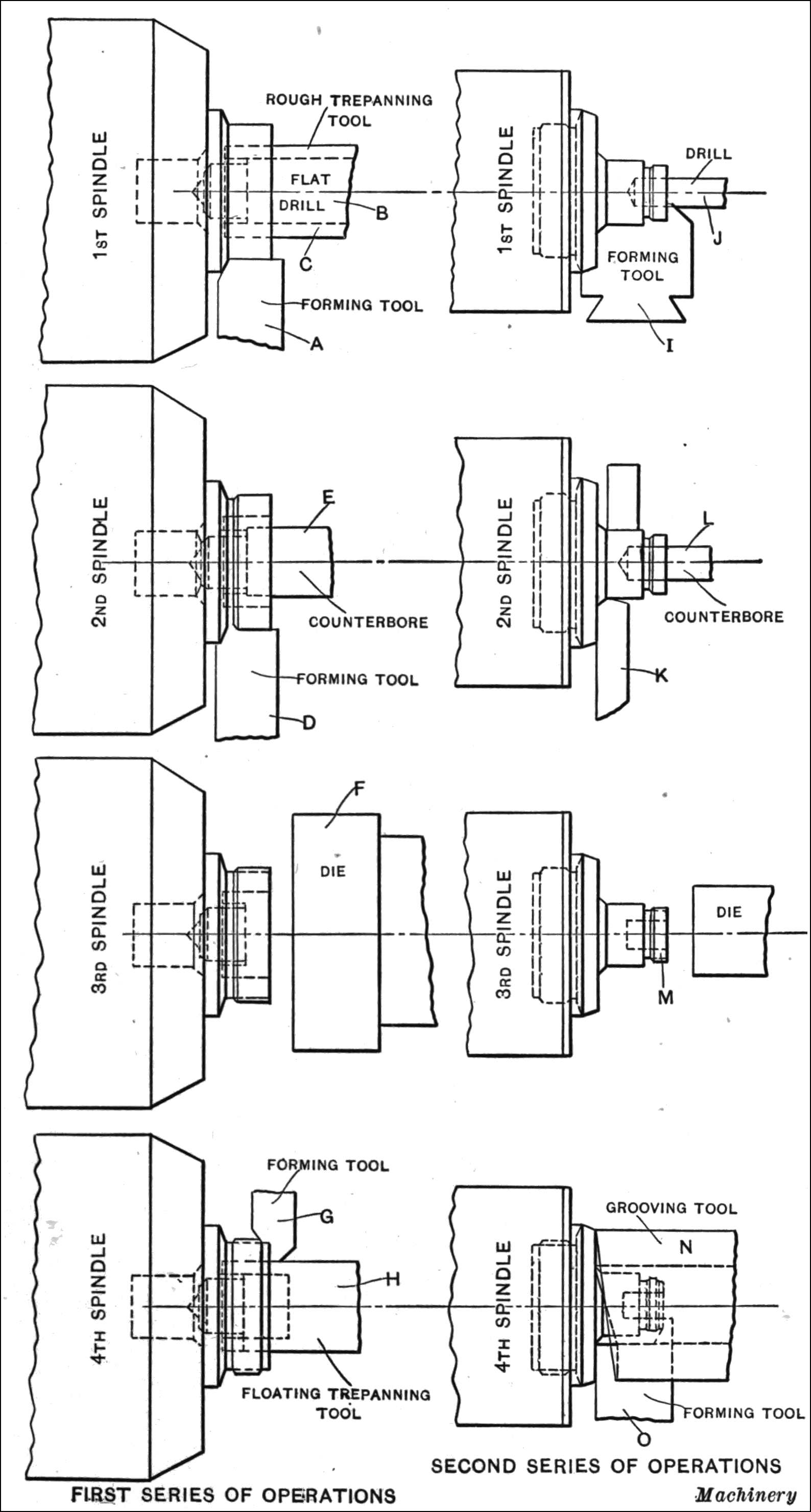
Fig. 13. Diagram Illustrating First and Second Series of Operations on Fuse Body on “Gridley” Automatic
Machining Shrapnel Fuse Parts on “Gridley” Automatics.—The machining of fuse parts for the British shrapnel shell on “Gridley” single- and multiple-spindle automatics, made by the Windsor Machine Co., Windsor, Vt., forms the basis of several interesting tooling equipments. A number of the parts are machined from hot-pressed brass forgings, so that they must be handled separately. The fuse socket, as has been previously described, is made from a brass forging and is machined complete in two operations on a 3¹⁄₄-inch “Gridley” automatic turret lathe of the single-spindle type. The manner in which the work is loaded in the chuck and held for the first series of operations is shown at A in Fig. 12. The rough blank a is first placed over the spring fingers b, which are held in a holder clamped in the turret, but are free to rotate. When the work is pushed into the chuck, it forces back spring-ejecting stud c, which, as soon as the pressure of the chuck is released, ejects the work.
As the loading device operates on the first slide of the turret, the first machining operation takes place on the second slide. This is a comparatively simple operation and consists in boring the central recess with a tool d and chamfering with tool e. The turret is then indexed, bringing the internal necking tool f into position. This is held in a holder and is operated by the forward motion of the forming slide. Following this, tap g is brought into position to thread the recess in the socket. The operation of the turret is now stopped automatically until the operator loads a new piece in the chuck. The tapping is done with the spindle running in the forward direction on slow speed. After the hole has been tapped, the spindle is reversed and operated at a higher speed. The spindle continues to run backward for loading, and is still running backward, but slowed down, at the time of the second operation. It is for this reason that the boring tool d operates on the reverse side of the hole, and tool e is mounted upside down. At the third operation, the spindle is still running backward but is speeded to its highest speed while the internal necking is done with the tool on the reverse side of the hole.
Second Operation on Fuse Socket.—The method of holding the fuse socket for performing the second operation on the 3¹⁄₄-inch “Gridley” single-spindle automatic turret lathe is shown at B in Fig. 12. The socket h, which has now been threaded, is screwed onto the body of special arbor i, fitting in sleeve j that is gripped by the spring collet. On the reduced end of arbor i is a nut which serves to clamp the work up against the face of sleeve j. The method of using this arbor is as follows:
To chuck the work, sleeve j and its auxiliary members are removed from the spring collet, and the work is screwed onto the nose of arbor i, the position of which is locked by means of a nut on the stem of the arbor. The entire arbor is then replaced in the collet and the machining operations performed on the work. This type of arbor is necessary because of the heavy cutting with the wide forming tool which would tighten the piece on the threaded nose to such an extent that it could not be removed when finished. With this device, it is only necessary to hold the square end of arbor i in a vise, and loosen the work by relieving the nut on the arbor. In order to facilitate the work, two arbors of this type are provided with each of the machines employed.
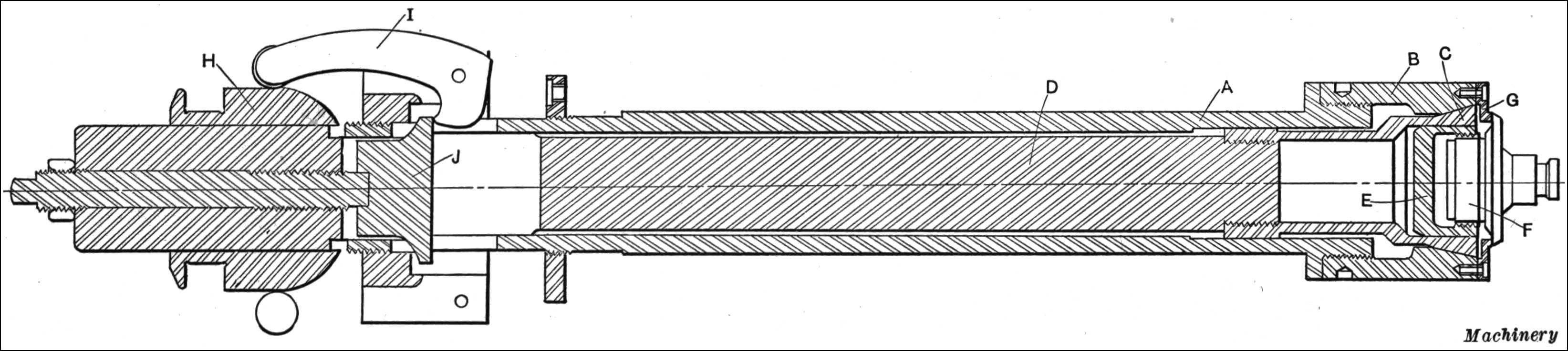
Fig. 14. Section through a “Gridley” 3¹⁄₄-inch Automatic Turret Lathe Spindle showing Method of chucking Shrapnel Fuse Body
The operations performed in the first position consist in forming the external diameters with tool k, facing with the side tool, and drilling with drill m. The second turret face is now skipped and the third brought into position, presenting self-opening die n which threads the work. At the fourth indexing of the turret slide, the hole is reamed with reamer o and tool p chamfers the face, completing the work. The forming done at the first indexing of the turret slide is performed on slow speed; the spindle speed, however, changes to high at the third position and back to slow just before the fourth position.
Machining the Fuse Body.—The fuse body is made from a hot-pressed brass blank, and is machined in two chuckings in “Gridley” multiple-spindle automatics. The first series of operations is performed in a “Gridley” 1¹⁄₄-inch multiple-spindle automatic in the order shown to the left in Fig. 13. The work is loaded in the chuck by hand. Forming tool A now advances and rough-forms the outer diameter, whereas flat drill B and trepanning tool C combine to drill the central hole and trepan the narrow channel. At the second spindle position, tool D finish-forms and necks the outer surface, while tool E counterbores the surfaces of the recess. Die F at the third spindle position now threads the body, and at the fourth spindle position forming tool G turns down the outer end of the thread while a floating trepanning tool H finishes the counterbored and trepanned surfaces. It should be mentioned here that the hot-pressing of this brass part makes it extremely difficult to machine, so that the edges of the tools dull rapidly.
Second Series of Operations on Fuse Body.—The method of holding the fuse body while the second series of operations is being performed is shown in Fig. 14. The work-spindles A of the machine are fitted with special nose-pieces B, the inner surface of which is chamfered to receive the spring collet C, which is threaded to the end of draw-back rod D. The work is not gripped directly by the spring collet, but is first screwed into a special bushing E, having thin walls as shown. This bushing is not split but springs sufficiently to permit it to be closed in on the work and released when the collet pressure is removed. A flange G attached to the end of the spindle nose serves as a stop for the work and a gaging point for the operations. The regular collet closing mechanism is used, but as may be seen in the left-hand end, the finger holders are reversed. When the clutch ring H is pushed forward by the chuck-closer gripping fingers I swivel and draw rod D backward through contact with flange J. When the clutch ring H is moved backward, the gripping fingers release rod D, relieving the pressure of the collet on bushing E and the work.
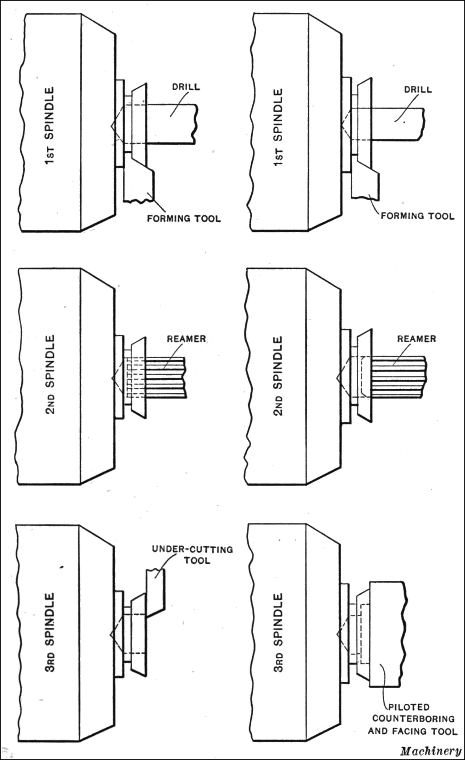
Fig. 15. Diagram illustrating Set-up for machining Timing Train Rings on “Gridley” Automatic
Referring again to Fig. 13, the second series of operations on the fuse body is shown to the right of the illustration. At the first spindle position, forming tool I advances and forms the exterior diameters, while drill J drills the hole in the end. At the second spindle position, the rear part of the work is supported by a roll back-rest, while the regular turner K takes a cut across and chamfers the shoulder. At the same time counterbore L comes in, cleans up the drilled hole and faces the bottom. At the third spindle position, the diameter M is threaded with a plain die. At the fourth spindle position, a tool N operated from the turret cuts a series of concentric grooves in the flange of the fuse body. The grooving tool is cut away to clear the forming tool O which takes a light cut over the grooved face, finishing the body as illustrated.
Machining the Stationary Timing Train Ring.—The machining operations on the stationary timing train ring are shown to the left in Fig. 15, and as can be seen are of a comparatively simple nature. This fuse part is made from a Tobin bronze bar in a 2³⁄₈-inch “Gridley” multiple-spindle automatic. At the first spindle position, a drill held on the turret drills the hole, and a forming tool on the cross-slide forms it to shape and breaks it down for the cut-off tool. At the second spindle position, the piece is reamed, and at the third position it is faced off with an under-cutting tool. In the fourth spindle position, not shown, the finished piece is cut off, and the stock is fed out.
Machining the Graduated Timing Train Ring.—The machining operations on the graduated timing train ring are almost identical with the stationary ring and are shown diagrammatically to the right in Fig. 15. This part is also made from a bar of Tobin bronze in a 2³⁄₈-inch “Gridley” multiple-spindle automatic. The only difference in the operations on this part is in the use of a combination floating counterbore, and facing tool provided with a roller pilot.
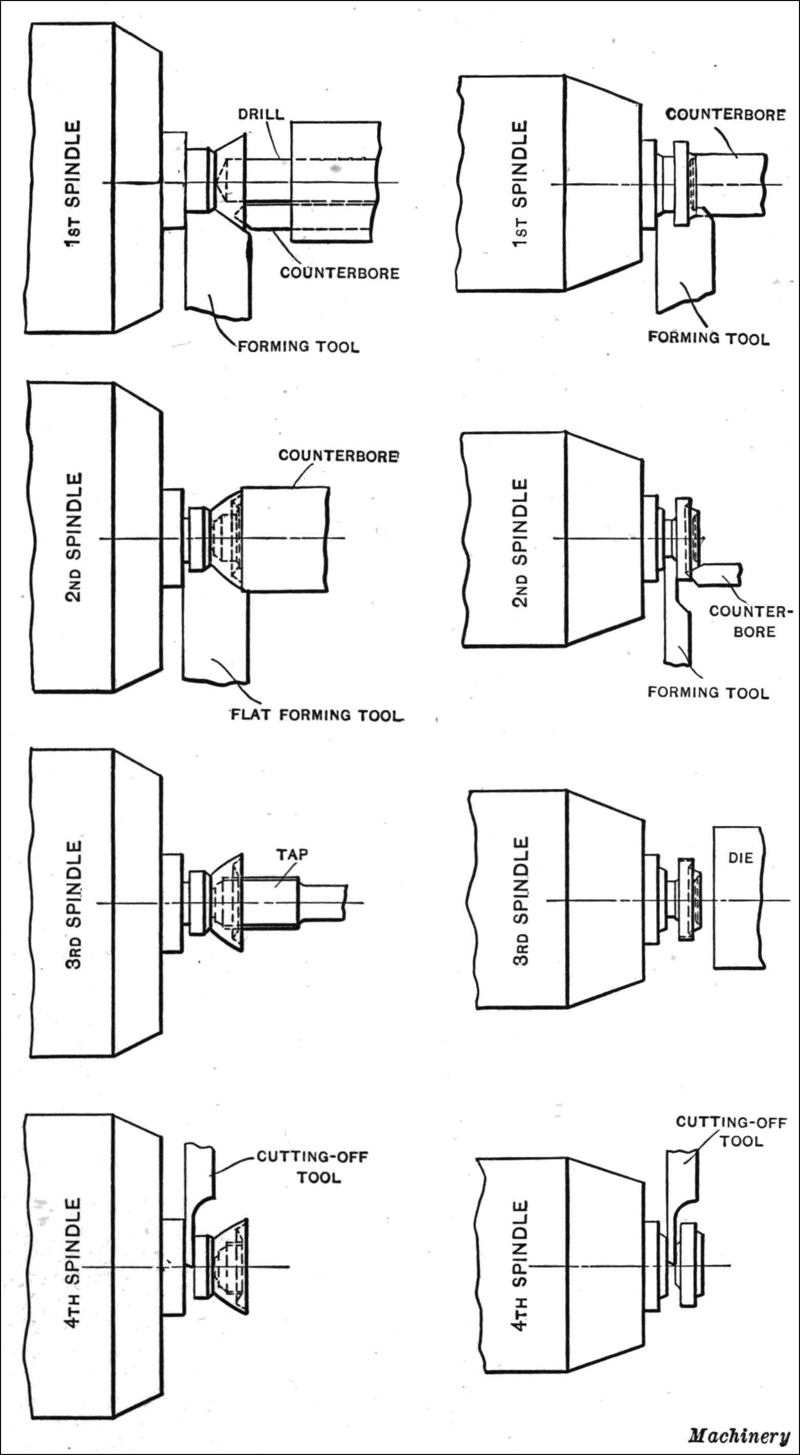
Fig. 16. Diagram Illustrating Set-ups for machining Closing Cap and Bottom Closing Screw on “Gridley” 1³⁄₄-inch Multiple-spindle Automatic
Machining the Closing Cap and Bottom Closing Screw.—The closing cap and bottom closing screw for the shrapnel timing fuse are made from brass rod with a comparatively simple tool set-up as shown in Fig. 16. The machine used is a 1³⁄₄-inch “Gridley” multiple-spindle automatic. The machining operations on the closing cap are shown to the left in the illustration, and consist in drilling, counterboring, forming, threading, and cutting off. The operations on the bottom closing screw, shown to the right of this illustration, are counterboring, forming, recessing, threading, and cutting off.
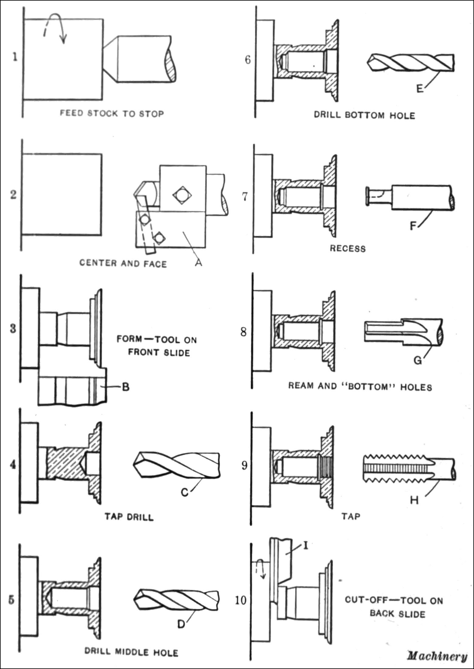
Fig. 17. Method of machining Fuse Hammer on a No. 2 Model G Brown & Sharpe Automatic Screw Machine equipped with an Eight-hole Turret
Making Fuse Parts on Brown & Sharpe Automatic and Hand Screw Machines.—A brief description of two of the many interesting set-ups on Brown & Sharpe automatic and hand screw machines for making timing fuse parts is given in the following. Timing fuse parts are made from several different materials. The screws and other small members as a rule are made from brass rod, whereas the parts such as the capsules, primer cups, etc., are made from sheet brass. Other members, such as the fuse body or stem, are made from different alloys and metals such as copper, copper aluminum, aluminum, etc.
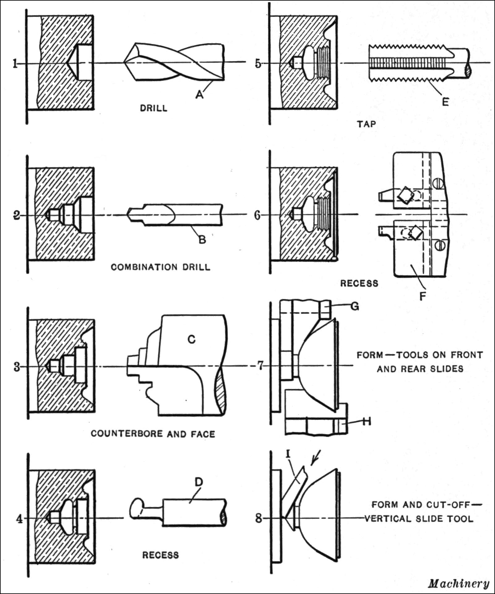
Fig. 18. Diagram Illustrating Method of Machining a Fuse Nut on a No. 6 Brown & Sharpe Hand Screw Machine
Set-up for Making Fuse Hammers.—The method of making a fuse hammer on a No. 2 Model G Brown & Sharpe automatic screw machine provided with a special eight-hole turret is shown diagrammatically in Fig. 17. This part is made from ⁷⁄₈-inch round brass rod and is finished complete in the screw machine. First, the stock is fed out to the stop in the turret. Second, the end is centered and faced with tools held in tool-holder A. The body is then formed with a circular tool B working from the front cross-slide; at the same time the turret is revolved, bringing tap drill C into operation. The forming tool is working at the same time as the drills. The turret is again revolved and drill D for finishing the middle hole is brought in and completes its operation. At the next index of the turret, drill E finishes the bottom hole. The turret is now indexed and a recessing tool-holder carrying tool F advances and is brought into operation to recess the work by a pusher on the cross-slide. The turret is again indexed and a reamer G is advanced to bottom and ream the holes. Upon the next index of the turret, tap H threads the work, which is finally cut off with circular tool I. The stock is rotated at 973 R. P. M. forward and backward for drilling and turning, and at 421 R. P. M. forward for threading. The stock is cut off rotating backward. The surface speed for the forming tools is 220 feet per minute and 31 feet per minute for the tap.
Tool Set-up for Making Fuse Nut.—The fuse nut on the Russian timing fuse is made from 1⁷⁄₈-inch round brass rod in a No. 6 wire-feed Brown & Sharpe hand screw machine as shown in Fig. 18. First the stock is fed out to length, being gaged by a stop in a vertical slide, which is held in the turret. The turret is then indexed and drill A drills the large hole. The turret is now revolved and the combination drill B is advanced. The turret is again revolved and counterbore C faces and counterbores the work. Upon the next index of the turret, a vertical slide tool-holder carrying recessing tool D is advanced. This tool-holder is operated by a handle attached to the holder. The turret is again indexed and tap E threads the work. After this the turret is indexed and the work is recessed with a tool-holder F carrying two cutters which balance each other in cutting. The seventh operation is performed from both the front and rear cross-slides with tools G and H. The eighth operation is cutting off. This is performed with a special vertical slide tool-holder held in the turret and operated by a handle. The stock for these operations is rotated at 352 R. P. M., giving a surface speed for the forming tools of 180 feet per minute and 66 feet per minute for the tap.
Making Fuse Parts on Hand Screw Machines.—The demand for shrapnel fuse parts has been so great that time has not been taken in all cases to tool up automatic screw machines before production has been started. In order to get parts out quickly while automatic machines are being tooled up, hand screw machines have been made use of. These machines are also used to a large extent on small orders and to help out production in general. Fig. 19 shows an F. E. Wells & Son Co. hand screw machine working on shrapnel fuse parts. The capacity of this machine is for ⁷⁄₈-inch diameter rod and it will tap or drill ¹⁄₂ inch diameter. Shrapnel fuse parts are produced on this machine at the rate of from 25 to 100 pieces per hour.
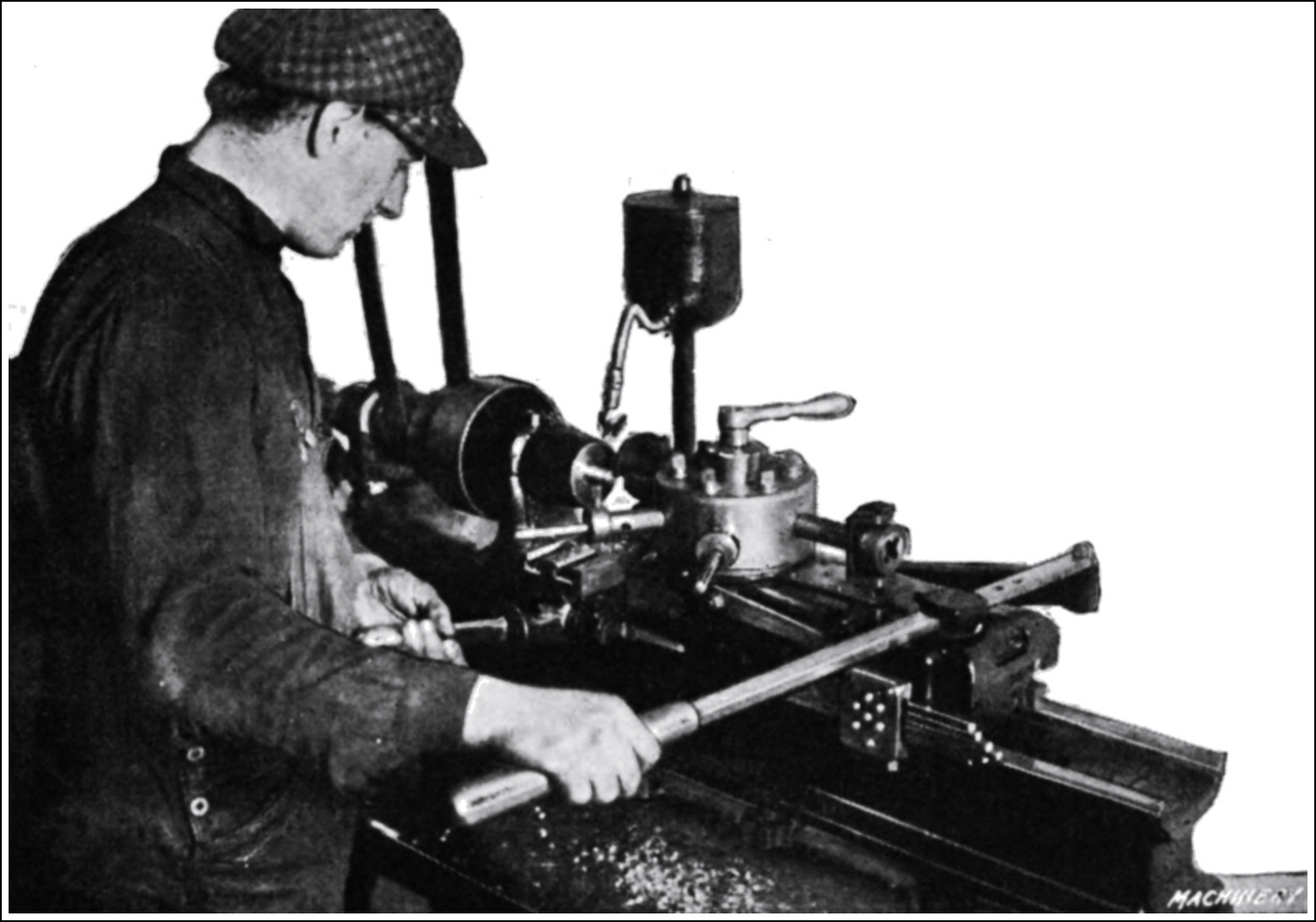
Fig. 19. Machining Fuse Parts on F. E. Wells & Son’s Hand Screw Machine
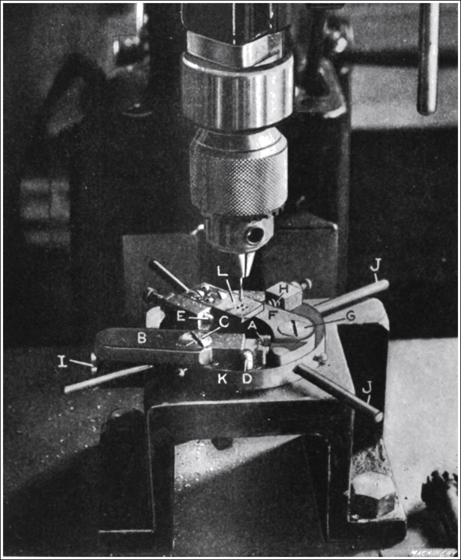
Fig. 20. Drilling Percussion Primers on a Leland-Gifford Ball Bearing Sensitive Drilling Machine
Drilling Percussion Primers for Fuses.—The percussion primer, used in the American combination fuse shown in Fig. 3, Chapter I, is made in a Brown & Sharpe automatic screw machine from brass rod in two operations. Following the screw machine operations, four holes about ¹⁄₃₂ inch in diameter are drilled through this bushing, employing a special “snap index” jig in a high-speed ball-bearing drilling machine made by the Leland-Gifford Co. of Worcester, Mass. (See Fig. 20.) The extremely small size of this part makes it difficult to handle, so the jig was designed with a special loading arm to facilitate rapid handling. The jig consists of a platform base bolted to the table of the drilling machine. Upon this is the index ring, which is turned by handles J and indexed for the four drilling positions by spring plunger I. The center of rotation is in the center of the four holes in the part. B is the loading lever, with a nest A at the end into which the work is slipped. This lever swings on stud C. The work is located in the swinging arm B when it is in the position shown in the illustration, with the arm B resting against stop D. The arm is then swung under the drill until it reaches stop E. It is maintained in this position by spring plunger H that bears against lever F, fulcrumed on stud G. The side of this lever bears against the work and holds it firmly while the drilling is proceeding. The drill is guided by four bushings in plate L, mounted on the index ring. The operation consists in rotating the index ring to the four stations for drilling the respective holes. By means of this quick-indexing ring, and the high speed at which the Leland-Gifford drilling machine runs, it is possible to drill as many as 6000 pieces, or 24,000 holes in ten hours.
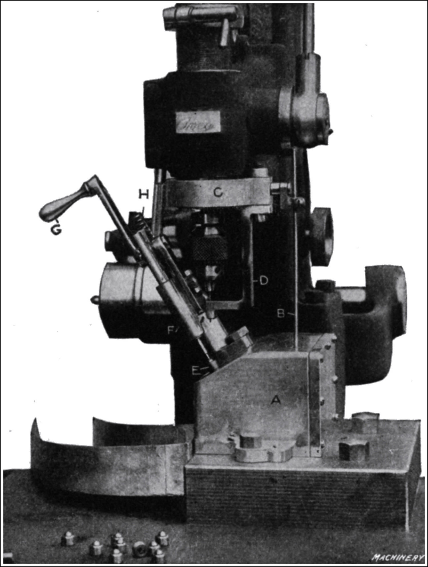
Fig. 21. Drilling Fuse Plugs on “Avey” Drilling Machine
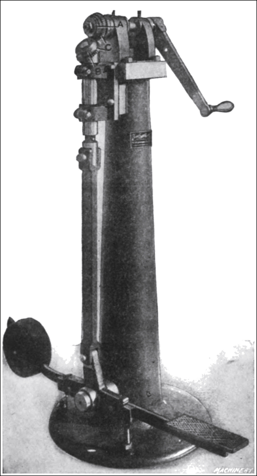
Fig. 22. Graduating Timing Fuse Rings on Dwight-Slate Marking Machine
Drilling Timing Fuse Plugs.—An application of a regular No. ¹⁄₂ “Avey” drilling machine, built by the Cincinnati Pulley Machinery Co., Cincinnati, Ohio, to the drilling of brass timing fuse plugs is shown in Fig. 21. The requirements are to drill three No. 55 (0.052 inch) holes through the dome of the plug; a number of pieces are shown on the table of the machine. These three holes practically run together at the inside of the dome, making it necessary to drill one hole at a time. The fixture used for this purpose is of unique construction. The body A is made of an aluminum casting, whereas the operating mechanism is of hardened tool steel. The drill spindle is operated by a foot treadle, connection being secured through rod B, passing down through the fixture and fastened to the spindle sleeve by the L-shaped piece and yoke C. The work E is held on a special work-spindle located inside the fixture that is indexed one-third revolution through the medium of rod B upon the raising of the drill spindle sleeve. The work holding-down and ejecting mechanism is supported in aluminum bracket F. Attached to this bracket is a supporting arm for the lower crank of lever G, which holds a segment gear. Bracket D carries the drill bushing.
After drilling the third hole, the operator depresses lever G, rotating the segment gear meshing in rack teeth in rod H, which lifts the latter up to eject the work and at the same time through a connection, not shown, raises the holding-down rod. The ejector, not shown, which is spring-controlled, returns to a neutral position immediately upon the ejection of the work, while the holding-down rod is still raised. The work, after being discharged, falls into a chute and is carried to the rear of the machine. The operation of this fixture is rapid, the production being from 9000 to 10,000 pieces in ten hours.
Graduating Fuse Timing Ring.—As has been previously stated, the adjustable ring on the timing fuse is graduated in seconds, starting at zero and running to twenty-one seconds. As shown in Fig. 22, the graduating of this timing ring is performed in the Dwight-Slate marking machine built by Noble & Westbrook, Hartford, Conn. The main arbor of the machine carries the stamping roll A and is turned by the handle shown. The timing ring to be graduated and marked is held at B. The two gears C prevent the stamp from “creeping” ahead or slipping on the work. The work-holding arbor, as shown, is held in a bracket and is raised to the stamp roll by pressure on the foot treadle. Two operations are required for stamping and graduating the timing ring. The first is marking the graduations and the second is putting on the figures.