Chapter IV · MACHINES AND TOOLS FOR SHRAPNEL MANUFACTURE
Reading edition
Reed-Prentice Co. Equipment for Machining Forged Shrapnel Shells.—In machining the 18-pound British shrapnel shell on the equipment furnished by the Reed-Prentice Co., Worcester, Mass., eight distinct operations are performed as follows: First, drilling a center hole in the closed end of the forging in a Prentice 16-inch ball-bearing sensitive drilling machine equipped with a special centering fixture; second, rough-turning the outside diameter, grooving, squaring the closed end and rounding the corners in a Reed-Prentice 14-inch heavy type automatic lathe; third, machining the powder pocket and diaphragm seat, as well as the internal and external diameters of the nose in a 14-inch Reed extra-heavy turret lathe; fourth, under-cutting band grooves and producing wave ribs in a 14-inch Reed engine lathe; fifth, boring, reaming, threading and facing the open end in a Reed 14-inch extra-heavy turret lathe; sixth, finish-turning outside diameter and radius on nose, also form-turning copper band in a Reed 14-inch heavy type automatic lathe; seventh, cutting off center projection on closed end of shell in a Reed 14-inch engine lathe; eighth, finishing brass socket to form, cleaning inside of socket and cutting off excess length of tube in a Reed 14-inch extra-heavy turning lathe.
First Operation on Rough Shell Forging.—The drilling of the center hole in the closed end of the forging is a comparatively simple operation, and is performed in an interesting fixture held on a 16-inch Prentice ball-bearing sensitive drilling machine. This fixture, which is designed for handling the work quickly, is shown in Fig. 1, and consists of the base casting A clamped to the table of the drilling machine. The entire back part of the jig swings on the trunnion B to provide a means for quickly removing the forging C from the arbor D. A locking-pin E is used for locating the fixture in its upright position for drilling. Bushing G in the top plate F of the fixture guides the combination drill and countersink.
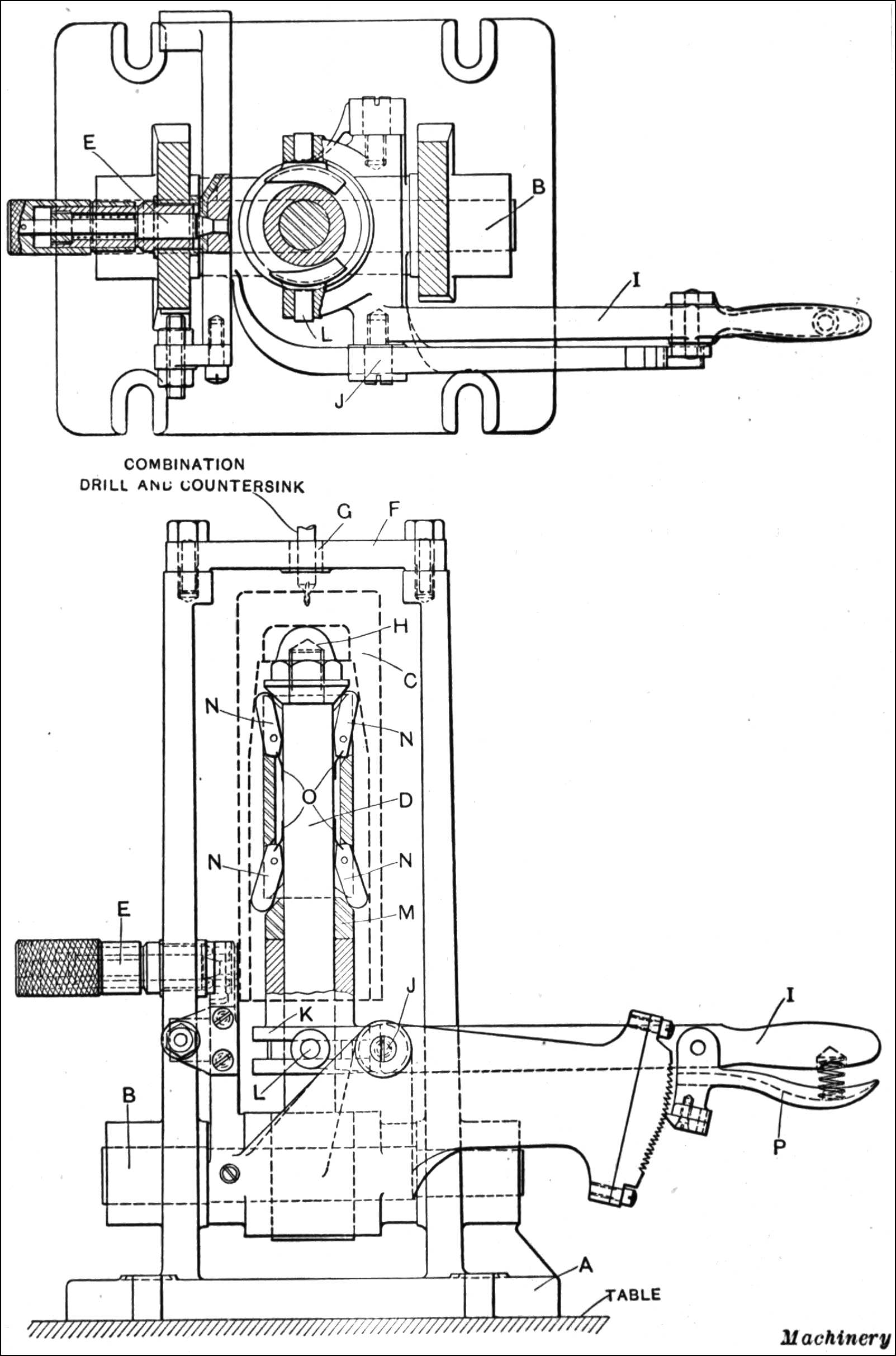
Fig. 1. Fixtures used for holding Shrapnel Shell Forgings when drilling Center Hole in a 16-inch Prentice Ball Bearing Sensitive Drilling Machine
The construction of the work-holding arbor is worthy of special attention. This arbor D has a cap H on its top end that acts as a stop for the inside of the forging, which, in being placed over the arbor, is located centrally and clamped by fingers N. To operate these fingers, hand lever I is depressed, and as this is fulcrumed at the point J, it causes collar K to rise on the arbor. Yoke L forms a connection between the lever and the collar with which the sleeve carrying fingers N is integral. Fingers N are fulcrumed in arbor D and are thrown outward to grip the forging when sleeve M is raised. Light springs O tend to keep the gripping fingers in a vertical position against the arbor when they are not being forced outward by the inclined surfaces on sleeve M. Handle I carries a spring pawl P that holds the sleeve M stationary while the forging is being center-drilled.
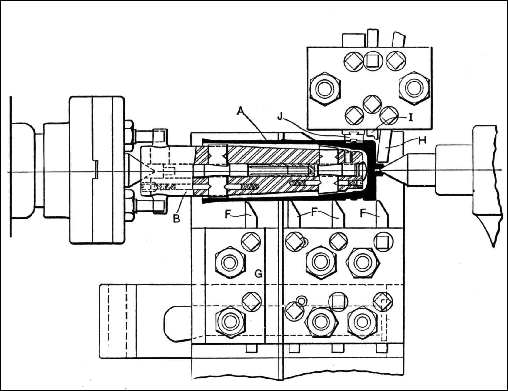
Fig. 2. Tool Lay-out for performing Second Series of Operations on Reed-Prentice Heavy Type Automatic Lathe
Second or Rough-turning and Facing Operations.—The second operation is performed on a Reed-Prentice 14-inch heavy type automatic lathe, as shown in Figs. 2 and 3. The forging A is held on an internal expanding arbor B, the driving part of which is supported by the head-center. At the closed end, the shell is steadied by the tail-center. The bottom of the shell rests against the end of the arbor which acts as a gage. In this setting, the external diameter of the forging is rough-turned by four tools F, mounted on the carriage G. This carriage has a travel slightly less than two inches, and an automatic throw-off is provided at the end of the cut that disengages the tools, draws them back and returns the carriage. At the rear of the carriage on this machine a facing arm is mounted on a heavy bar. Turning tools are carried on this facing arm, as shown, and when the front carriage feeds longitudinally a cam bracket O, bolted to the carriage, is carried along with it. Clamped on this bracket is an adjustable cam N held in place by screws. Cam roll M on the facing arm contacts with cam N, causing the facing arm to rock forward as the carriage travels longitudinally.
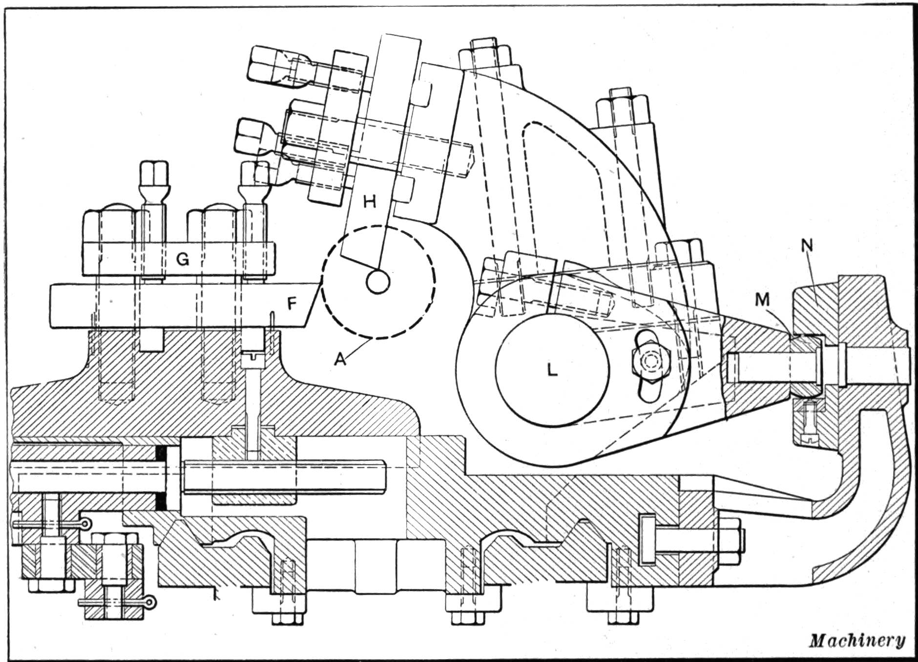
Fig. 3. Section through Reed-Prentice Automatic Lathe, showing Tool Arrangement
Referring to the plan view in Fig. 2, tool H, held in the arm, faces the end of the forging, tool I chamfers the corner, and tool J cuts the depression for the wave ribs, leaving a projection in the center from which the ribs are formed. It should be understood that the tools on the carriage and facing arm work together. One man can run two of these machines without trouble.
Third Series of Machining Operations.—The third series of operations on the shrapnel forging is performed on a 14-inch Reed heavy lathe with a specially large turret, as shown in Fig. 4. This lathe is fitted with a 12-inch three-jaw chuck, bored out to 3¹⁄₂ inches to permit the forging to extend into it. The forging A is put in the chuck as shown at B, and the jaws grip at C. The first operation is performed with a bar D carrying a blade cutter E that rough-bores the powder pocket, and tool F that rough-bores the mouth. The turret is now indexed, and a boring-bar carrying a blade G roughs out the diaphragm seat, while an auxiliary tool H faces the shell to length. At the next indexing of the turret the boring-bar I that carries the finishing tool J finishes the diaphragm seat and powder chamber.
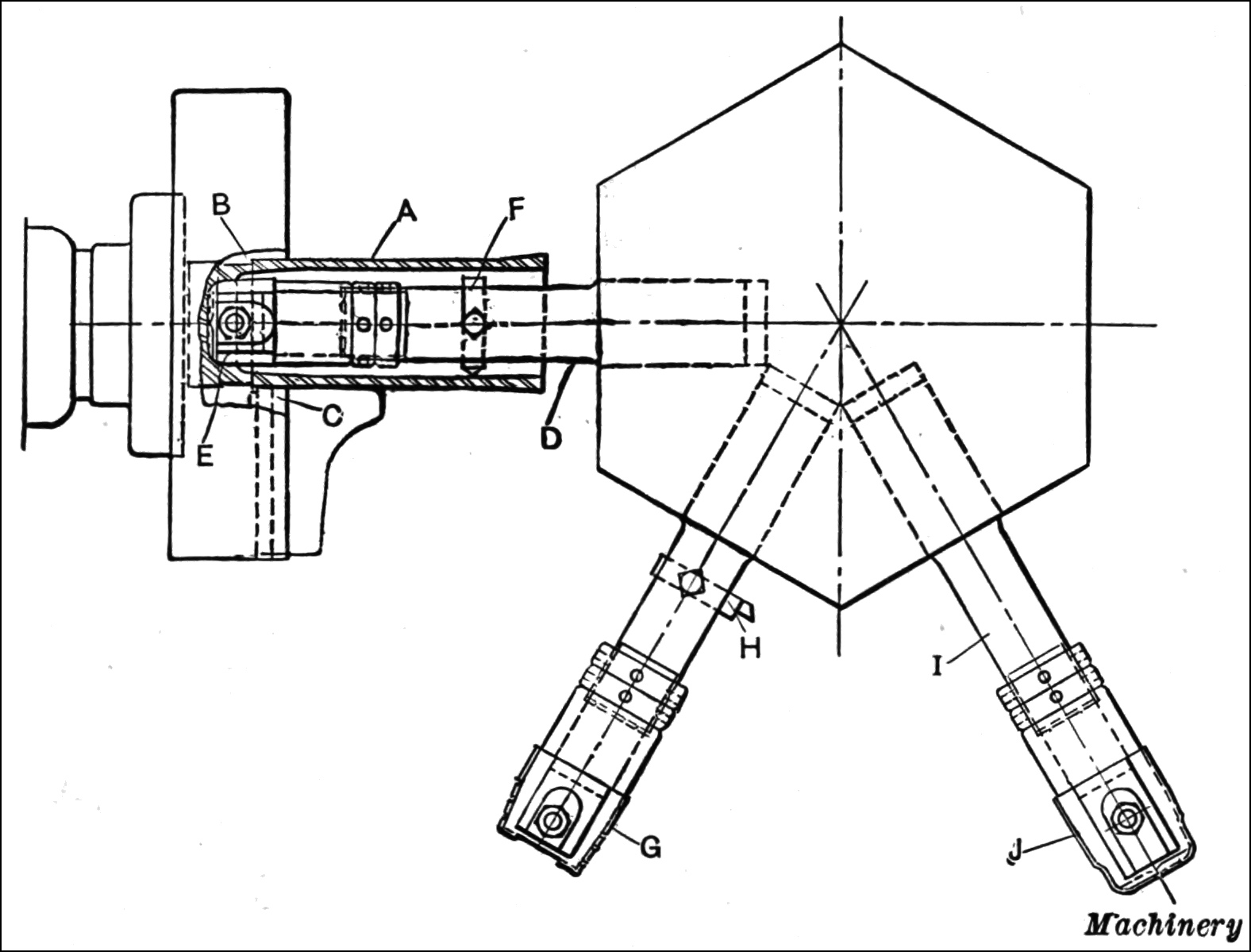
Fig. 4. Tooling Equipment for performing Third Series of Operations on 14-inch Extra-heavy Turret Lathe
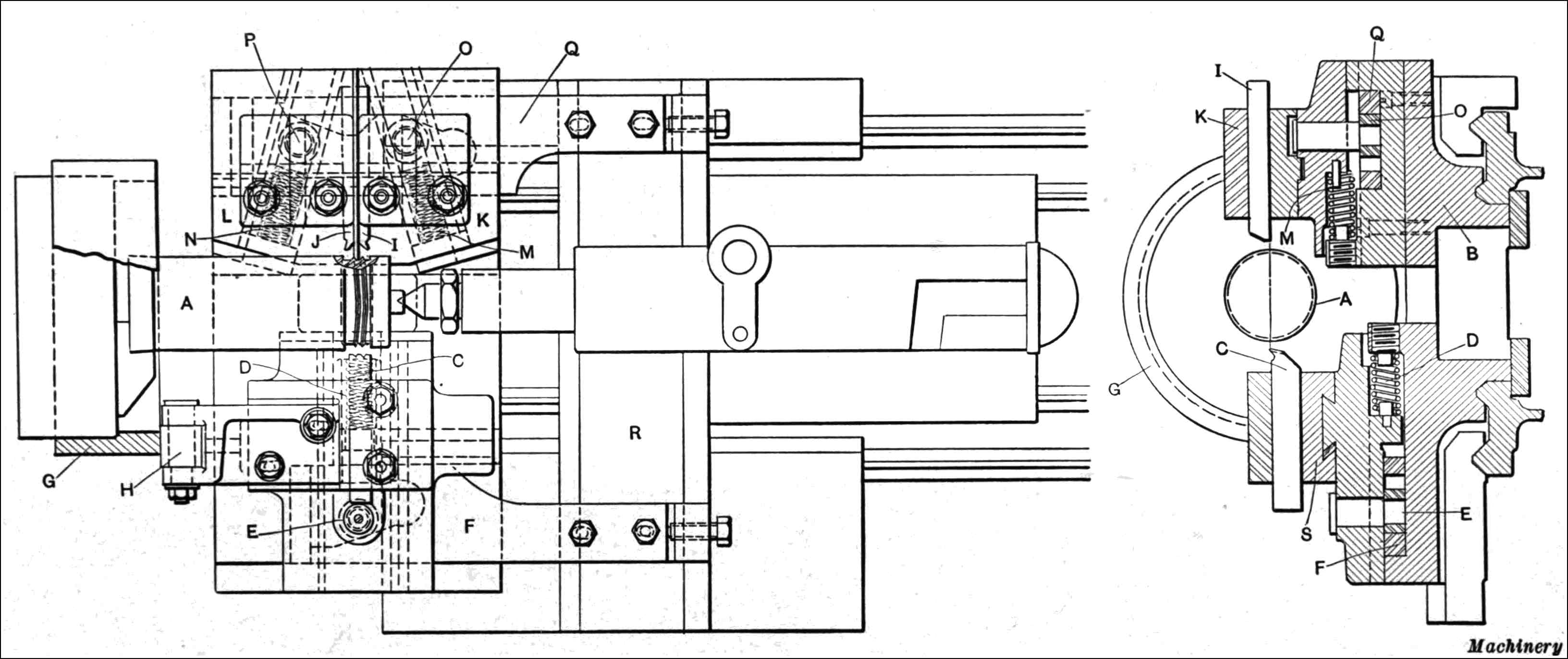
Fig. 5. Tools used for Under-cutting and Waving Band Grooves on Reed 14-inch Engine Lathe
Fourth Operation—Under-cutting and “Waving” Band Groove.—For the fourth operation, the forging is held in a 14-inch Reed engine lathe provided with an automatic attachment for under-cutting and waving the ribs for the copper band. The tool equipment used is shown in Fig. 5, where A is the forging held by one end in the chuck and supported on the opposite end by the tail-center. The tools are all located in holders on the heavy base block B, and their operation is controlled from the carriage R of the lathe. The cutting of the wave ribs is done by tool C at the front, held on a slide that operates on the top of block B. Spring D keeps the roll E on the lower slide of the tool-holder in contact with the cam slot in cam-plate F that is fastened to carriage R. When the carriage is traversed toward the chuck, the irregular surface of cam-plate F engages the roll and forces the tool-holder forward. Side motion to produce the wave is then effected by face-cam G, mounted on the chuck and contacting with the roll H. This roll is supported on a bracket forming an auxiliary slide S that carries the waving tool C. A stiff barrel spring keeps slide S in contact with the cam G. Thus, when the machine spindle revolves, the auxiliary slide is caused to oscillate back and forth far enough to give the desired amount of wave.
The under-cutting in the band groove is accomplished by tools I and J which are mounted on separate tool-slides K and L. These slides are fed in at an angle to the axis of the forging, against the action of coil springs M and N, by the cam surfaces of plate Q in which rolls O and P work. Plate Q is bolted to carriage R which, in advancing toward the chuck, forces in the under-cutting tools in the manner just described. The tail-center of this machine is fitted with a quick-acting mechanism so that it may be withdrawn quickly to insert a new piece.
Fifth Series of Operations.—Before performing the fifth series of operations, the forging is heated and closed in on the nose. It is then handled in the following manner: A Reed 14-inch heavy lathe, equipped with an extra large turret mounted on a special wide-bridge carriage carries tools for boring, reaming, threading and final squaring of the open end, as shown in Fig. 6. The shell forging for these operations is held in a three-jaw chuck provided with special jaws. In the first position the rough-boring of the nose and the rough-facing of the extreme end is performed with tools B and C. The turret is then indexed and tools D and E finish-ream the hole in the nose and face the end. The tap F is next brought into position, cutting the thread in the nose.
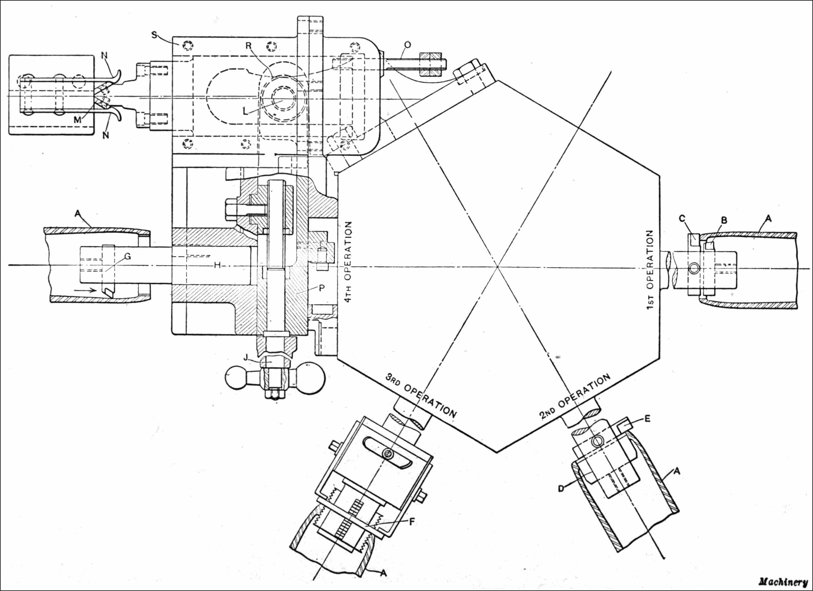
Fig. 6. Turret Tools held on Reed 14-inch Extra-heavy Lathe for performing Fifth Series of Operations
The turret is again indexed, bringing a special form boring tool into position. Here the boring tool G is carried in a bar H held in a holder of the cross-sliding carriage type that is fastened to two faces of the turret. By means of cross-screw J, the boring tool H may be drawn in or out at will. This tool operates as follows: As the turret is advanced, handle J is operated to let tool G enter the nose of the shell, and, upon the continued advance of the turret, arrow head M is forced in between and gripped by the fingers N. The turret is now backed away from the chuck, and while receding acts upon slide P through the medium of roll L and cam groove R. The plate containing cam groove R is attached to the arrow head M and consequently is held stationary while the turret is being withdrawn from the work. This backward movement of the turret is continued until the tool G is withdrawn from the work and slide S comes in contact with check-nuts on rod O, withdrawing arrow head M from fingers N and allowing the turret to be indexed ready for the first operation on the next forging.
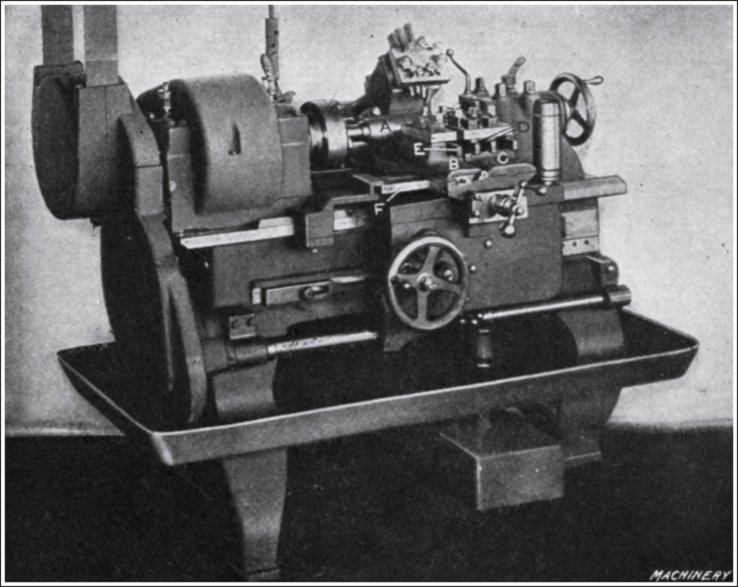
Fig. 7. Reed-Prentice 14-inch Heavy Type Automatic Lathe used for performing Sixth Series of Operations
Sixth or Finish-turning Operations.—The sixth series of operations is performed on a Reed-Prentice 14-inch heavy type automatic lathe, similar to that used for the second operation, and the machine is also operated in a manner similar to that previously described. The operations consist in finish-turning the outside diameter of the shell and turning the radius on the nose. In addition, the copper rifling band, put on previous to this operation, is turned to shape. Referring to Fig. 7, the shrapnel shell A is held by the tail-center at one end and is supported and driven from the other end by a plug screwed into it. This plug is held on the live center and is driven by an equalizing driver, coming in contact with pins in the special faceplate.
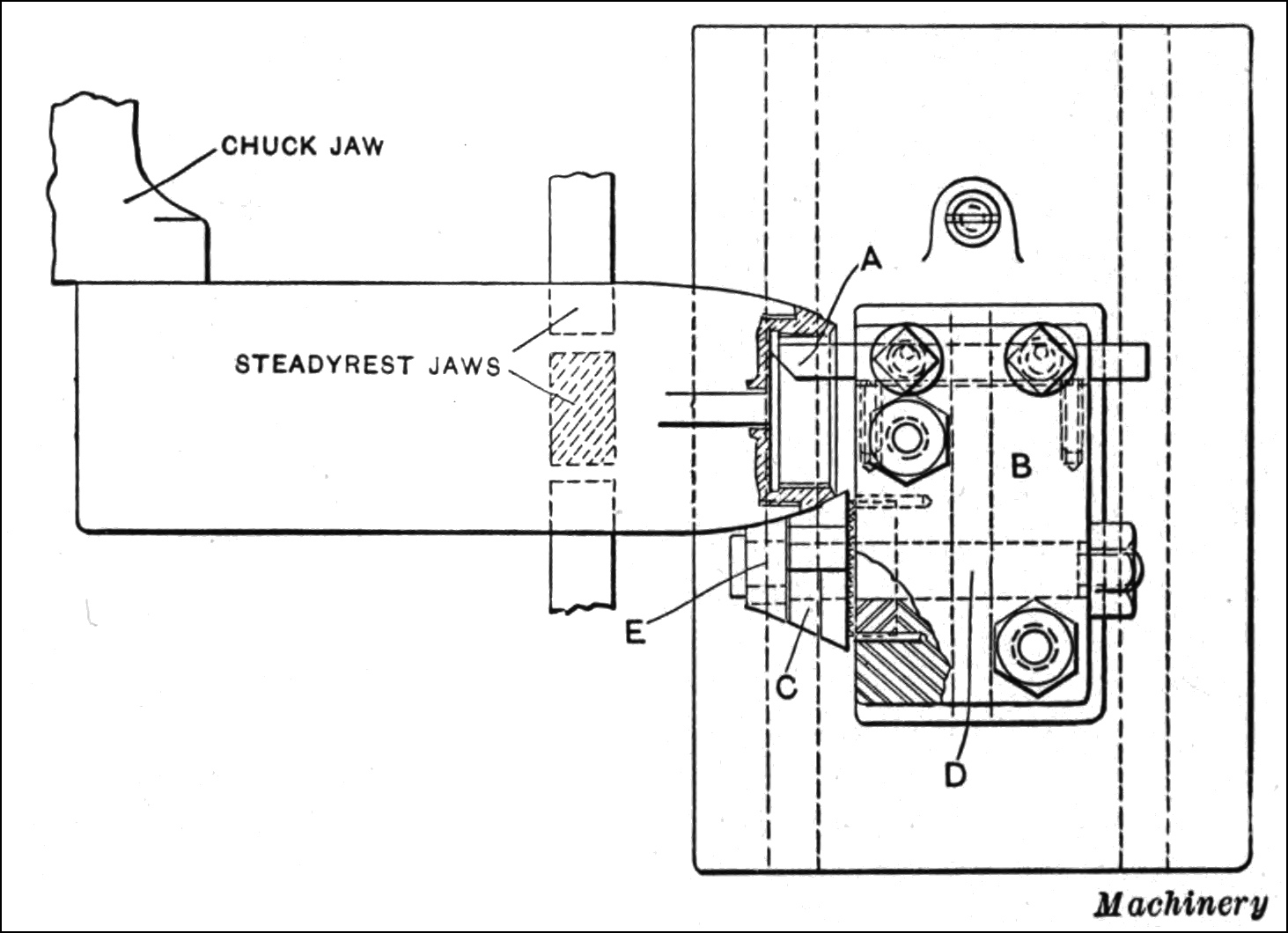
Fig. 8. Tools for machining Brass Fuse Socket on 14-inch Heavy Turning Lathe—Eighth Operation
Two slides B and C are carried on the front of the carriage. Slide C carries three tools D; two of these start in from the rifling band and turn in toward the nose, and the other works up toward the rifling band from the closed end. Tool E, carried in slide B, turns the curve on the nose of the shell and is controlled in its action by means of a slot in cam F in which a roller held to the slide operates. At the rear of the carriage is carried a facing bar attachment, as previously described in connection with the second operation. This attachment carries three tools, as illustrated, for machining the rifling band to shape, facing the closed end and chamfering the corner.
Seventh and Eighth Operations.—After the sixth operation, the fuse tube is threaded into the diaphragm, the bullets put in, and the hot resin poured in to keep them from rattling. The brass socket is then screwed into the nose and the fuse tube soldered to it. The shell is now ready for the seventh operation which consists in cutting off the center projection. This is accomplished in a Reed 14-inch engine lathe, provided with a faceplate chuck for holding and driving the shell at the open end, and a steadyrest for supporting it close to the point where the cutting is being done. The shell is now ready for the eighth operation, which consists in machining the brass socket to shape in an extra-heavy lathe as shown in Fig. 8. The tools used for machining are retained in a special holder on the carriage. Tool A, which is used for facing off the fuse tube and the brass socket, is inverted, starts at the center and is fed out toward the circumference. The external surface of the socket is machined with a circular forming tool C held on a stud D located in block B. The inward travel of this tool is limited by stop E coming in contact with the shell.
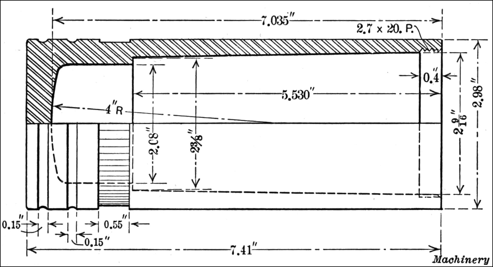
Fig. 9. Shrapnel Case made from Chrome-nickel Steel having High Tensile Strength on a Cleveland Automatic Screw Machine with Special Tool Equipment
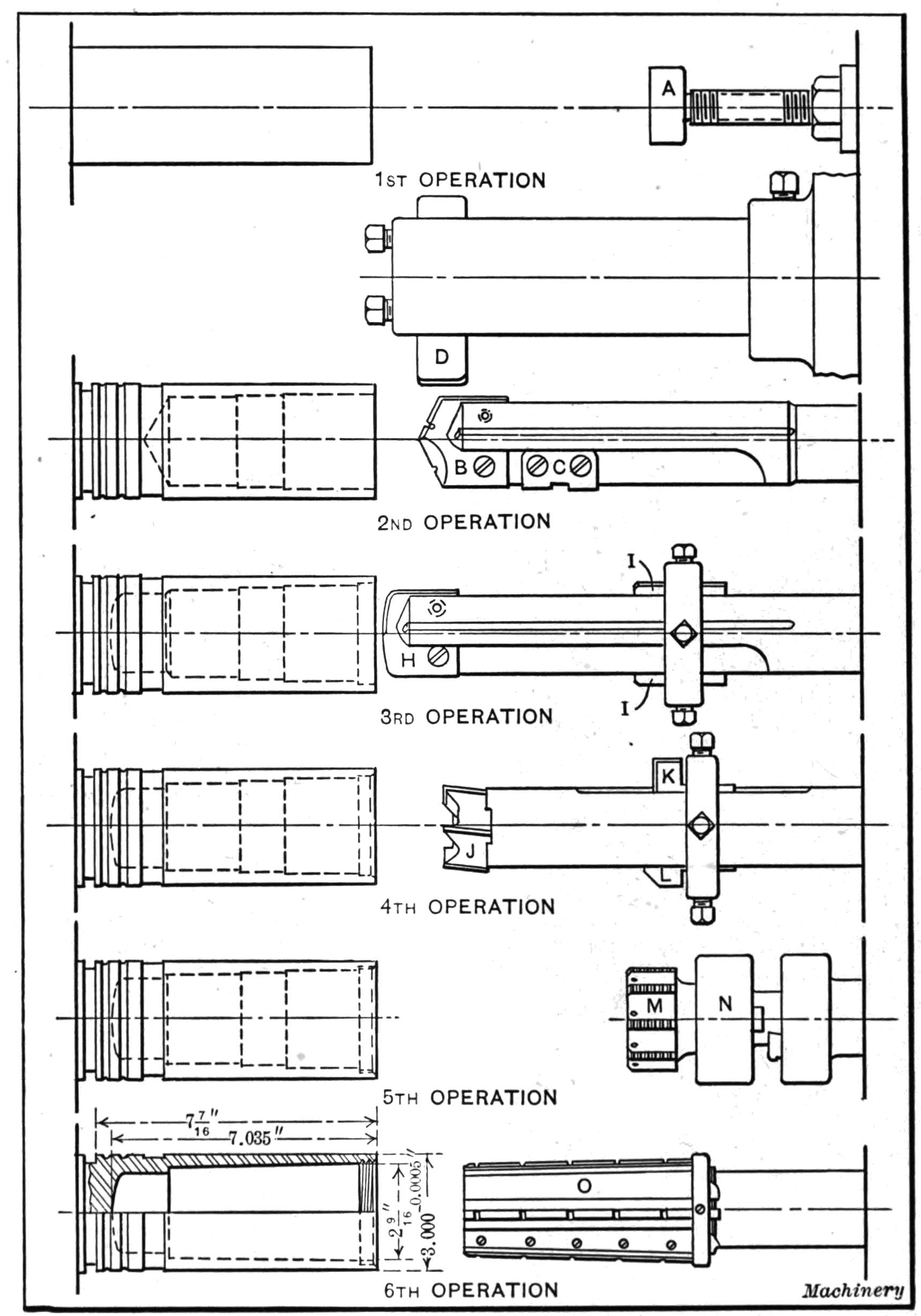
Fig. 10. Order of Operations on the Shrapnel Case
Making Shrapnel Shells on the Cleveland Automatic.—An unusual example of automatic machine work is that of producing the shrapnel shell shown in Fig. 9. This shell is made from a bar of 3¹⁄₁₆ inch chrome-nickel steel stock. The steel has a tensile strength varying from 125,000 to 135,000 pounds per square inch, and is extremely tough. The work is accomplished on a 3¹⁄₄-inch Cleveland automatic, and the tooling equipment, as shown in Figs. 10, 11, and 12, is interesting. While the general operation of the Cleveland automatic is well understood by many mechanics, the production of this piece illustrates a number of points in the operation of this machine which are not so well known. Therefore, it is advisable to explain in detail just how this interesting job is handled.
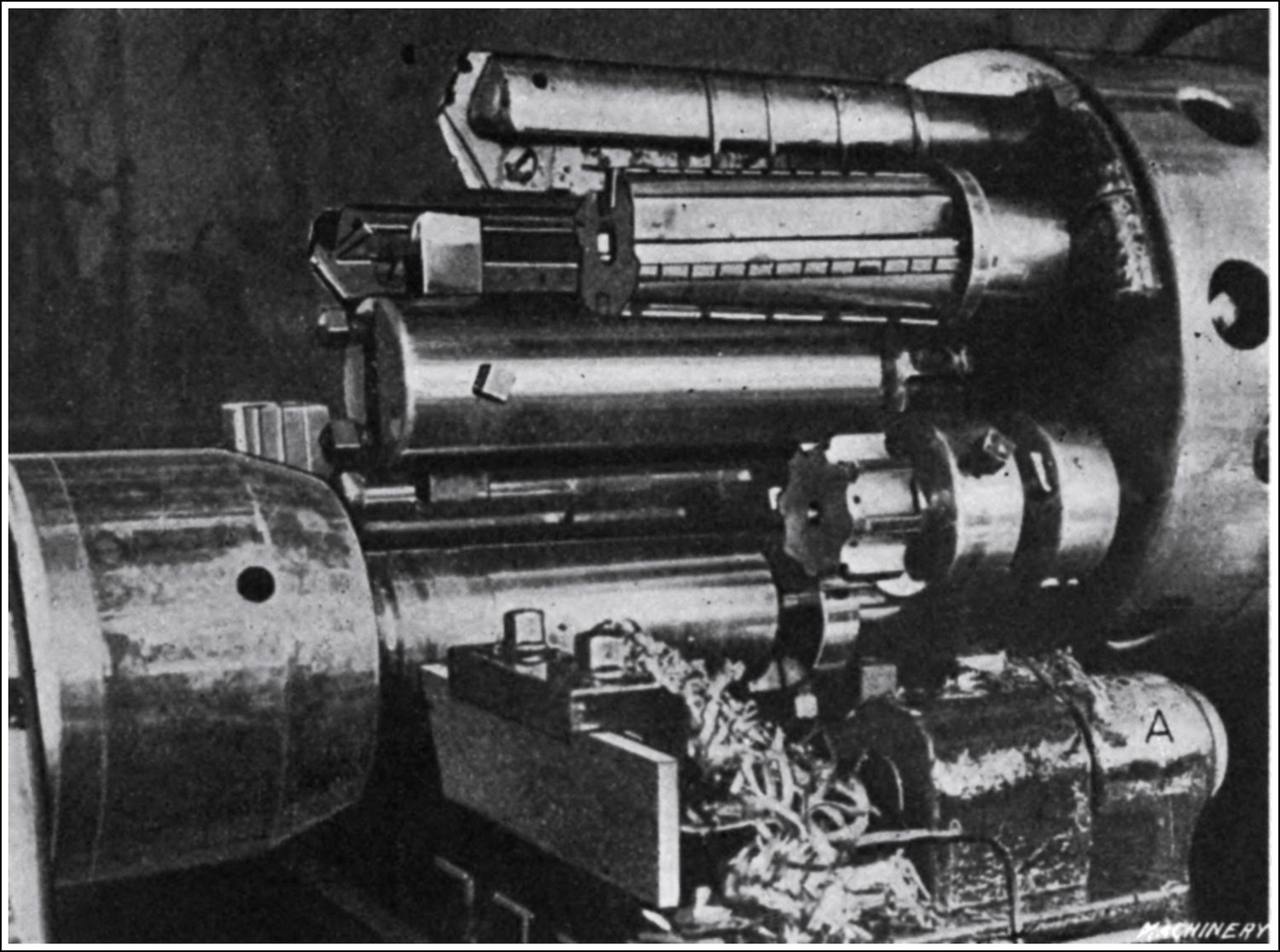
Fig. 11. Cleveland 3¹⁄₄-inch Automatic Screw Machine set up for making a Shrapnel Case in Twenty-five Minutes
The first operation, as the job was originally laid out, was to feed the stock out to the stop A, shown in Fig. 11, which is held on the cross-slide and operated by a lever on the base of the machine. This method has been improved upon since the photograph shown in Fig. 11 was taken, and the time reduced from twenty-seven and one-half minutes to twenty-five minutes (see Fig. 10 for improved method). The second operation is to rough-drill the large hole with an inserted bit B, step the hole for the taper reamer with cutter C and rough-turn the external diameter with cutter D held in a special turning attachment. This attachment envelops the shanks of all six tools in the turret in order to obtain support. The cutters in the attachment shown in Fig. 11 work in advance of the under-cutting forming tool E shown in Fig. 12, which is held on the rear cross-slide. The time required for the completion of the operations outlined is thirteen minutes.
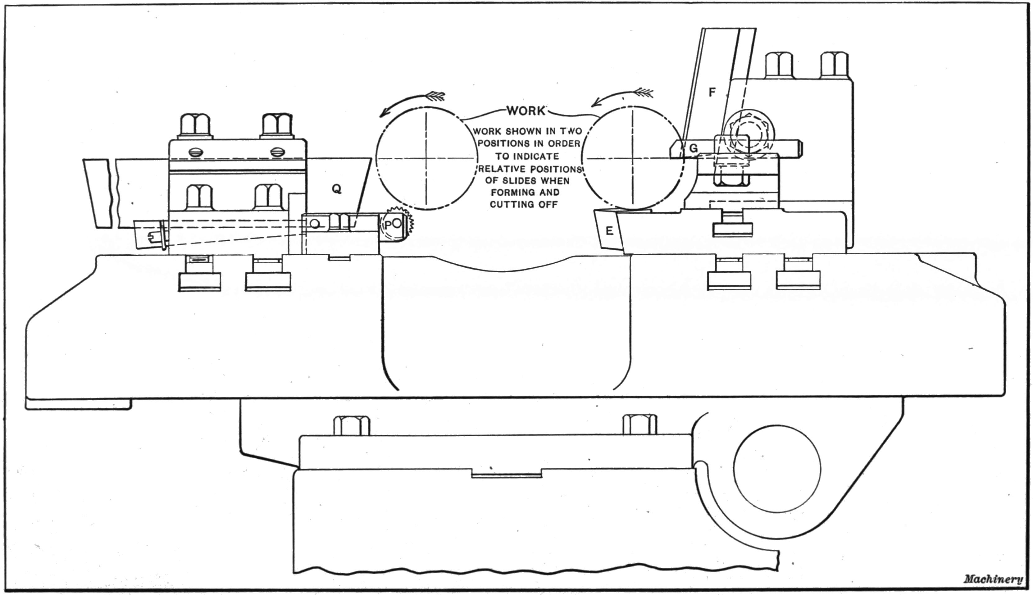
Fig. 12. Showing Tools held on the Front and Rear Cross-slides for performing the Knurling, Forming, and Cutting-off Operations on the Shrapnel Case
In the third operation drill H finishes the powder pocket, and two cutters I counterbore for the tap—time required three minutes. The fourth operation consists in finishing the diaphragm seat with the counterbore J, finishing the front end with inserted cutter K and breaking the corner to facilitate tapping with inserted cutter L, the time required being forty-five seconds. In the fifth operation the thread is cut with a tap M held in the tap-holder N in forty-five seconds. Then the turret is indexed and for the sixth operation the hole is taper-reamed with reamer O, provided with four inserted “Novo” steel blades, in ninety seconds. The last and seventh operation consists in knurling the band with a knurl P (see Fig. 12) mounted on the front cross-slide, and cutting off the shell with a cut-off blade Q retained in a holder on the rear cross-slide—time six minutes. The total time required to produce this shrapnel case by the improved methods illustrated by the diagram in Fig. 10 is twenty-five minutes.
There are several points of unusual interest in the production of this shrapnel case. One is the large amount of stock to be removed to form the hole; the second is the long taper-reaming operation—difficult work to accomplish satisfactorily on an automatic screw machine—and the third is the long outside forming operation which must be held to a limit of 0.0005 inch on the diameter. In order to accomplish this last operation successfully, the external diameter of the piece is first turned with a cutter held in a separate turning attachment, leaving only 0.010 inch on the diameter to be removed by a wide under-cutting or shaving tool E held very rigidly on the rear cross-slide. Not only must the case be exact as regards diameter, but it must not vary from one end to the other nor at any point throughout its length. The large shaving tool held rigidly in the manner illustrated in Fig. 12 accomplishes this result satisfactorily.
The material from which the case is made is so tough that some difficulty was met with in selecting a tool steel that would stand up for a reasonable length of time under cut. The drills and counterbores are tipped with “Novo” cutters and all the forming tools, including the cut-off tool, are also made from the same steel. The only cutting tool in the entire tooling equipment not made of this steel is the tap. The bar is rotated at sixty-four revolutions per minute, giving a surface speed for the external cutting tools of approximately fifty-one surface feet per minute.
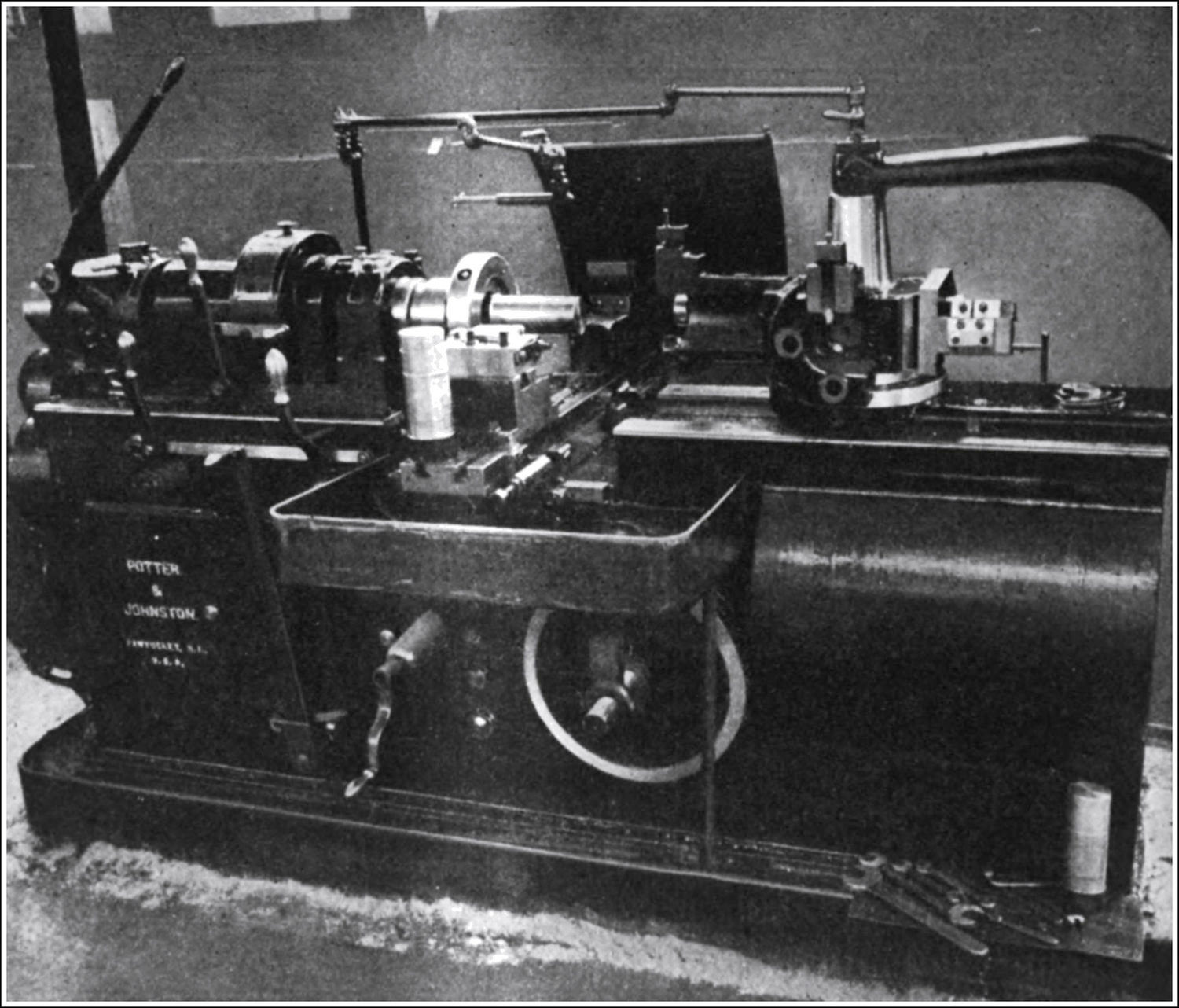
Fig. 13. First Operation on Shrapnel Shell, performed on a No. 6A Potter & Johnston Automatic Chucking and Turning Machine
Machining the British Forged Shell on Potter & Johnston Automatics.—In making the British forged shell on the Potter & Johnston automatic chucking and turning machine, three operations complete the work. The first operation completes the outside of the shell, except for the extreme end which is covered by the gripping mechanism of the chuck. The second operation finishes the inside of the shell and at the same time finish-turns the extreme open end. After the second operation is performed the shell is “nosed,” which consists in heating it in a lead bath and then striking it under a light press to close in the end. The third operation then follows, and consists in taking light cuts from the inside diameter and threading the open end of the shell.
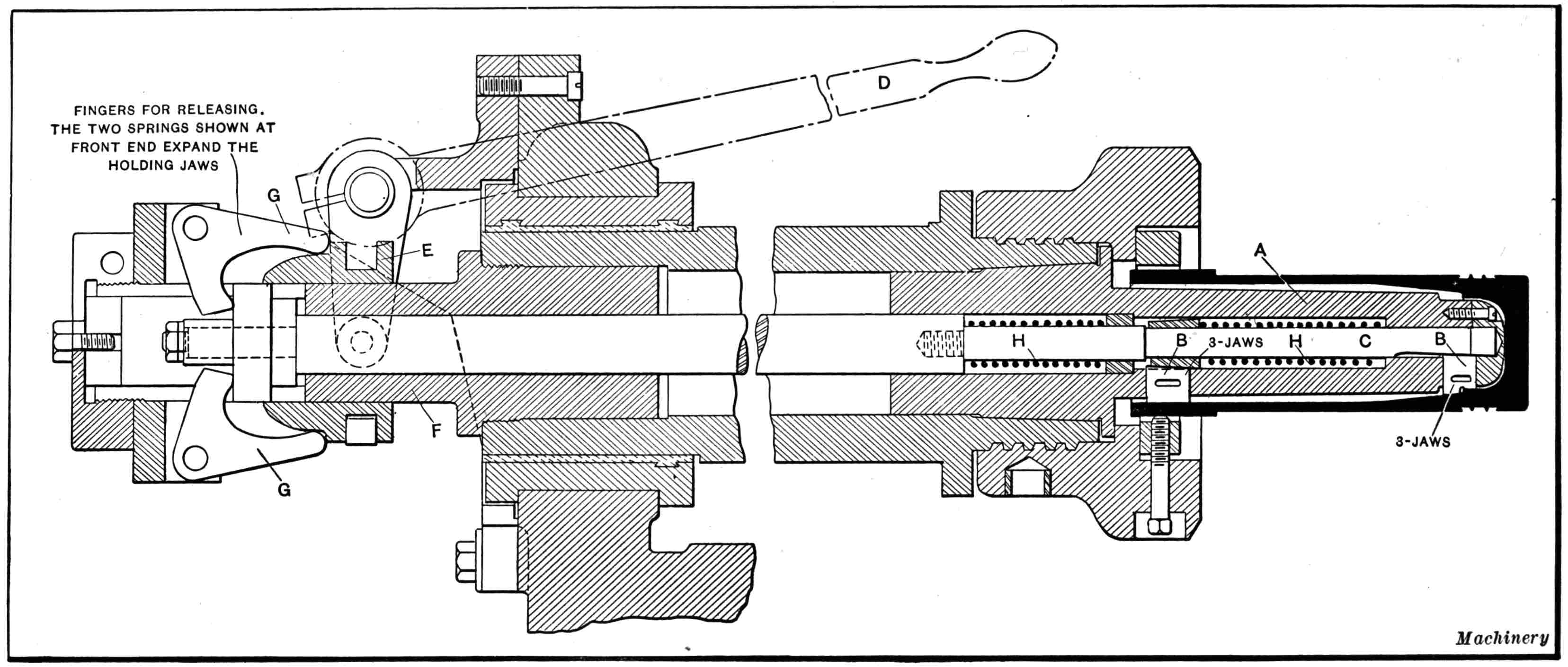
Fig. 14. Expanding Arbor and Chucking Mechanism used on Potter & Johnston Automatic Chucking and Turning Machines for performing First Operation on Forged Shrapnel Shells
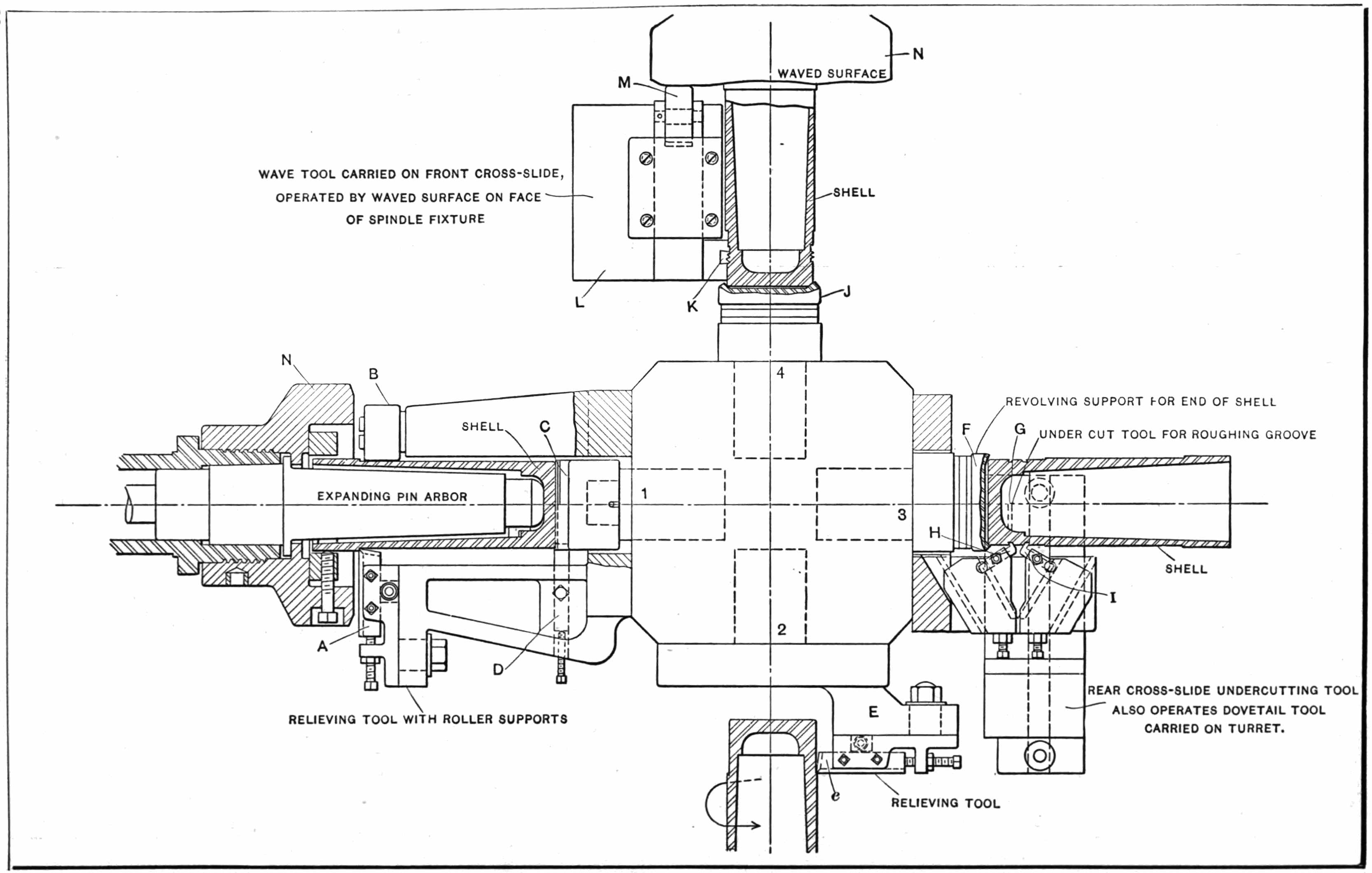
Fig. 15. Set-up on a No. 6A Potter & Johnston Automatic Chucking and Turning Machine for First Operation on Forged Shrapnel Shells
Method of Holding Shell for First Operation.—For the first operation, the shell is held on an expanding arbor of the type shown in Fig. 14. The arbor A is tapered on its rear end and is held in the nose of the spindle of the machine. The shell is pushed onto this arbor until the end of the arbor strikes the bottom of the shell. The gripping mechanism which comprises six jaws B and a draw-in plunger C is contained inside the arbor. The external diameter of the arbor is machined to practically the same shape as the internal diameter of the shell, but is smaller. The jaws are held in slots which control their movement in every direction except radially. They are forced out radially by means of the draw-in bar C which is provided with tapered seats that engage the inward end of the jaws. The bar C is operated by a hand lever D that extends up over the top of the machine, is fulcrumed in a bracket on the rear bearing cap, and is connected to a sliding sleeve E.
In clamping the work on the arbor, lever D is lifted up, this action drawing the sliding collar E to the right along the sleeve F, which, in turn, allows the forward end of the fingers G to close in. This releases the pressure of the outer end of the fingers on the draw-in bar C. When the pressure from bar C is released by means of handle D, heavy coil springs H then come into action forcing the draw-in bar back and expanding the clamping jaws. Additional clamping means are provided by three set-screws which are brought to bear on the work after it has been clamped in position by the jaws. To release the work, the reverse action takes place, that is, lever D is forced down which slides the collar E to the left, operating the fingers G, which, in turn, overcome the pressure of the springs H, allowing the clamping jaws B to collapse.
First Machining Operation Set-up.—The order of the first series of operations in machining a forged shrapnel shell is as follows: First, rough-turn 7 inches along body of shell, face end and chamfer; second, finish-turn 2¹⁄₂ inches along shell; third, rough-groove for copper band and dovetail; fourth, turn waves in groove.
For the first operation, the work is held on the expanding arbor shown in Fig. 14, and the tool equipment, which is of an unusually interesting character, is shown in Fig. 15. The first rough-turning operation, accomplished by turret tool A, which is of the relieving type to be described later, is held on the first face of the turret and roughs down the body of the shell. On the opposite side of the holder is a roller support B which supports the shell while the turning tool is in operation. The end of the shell is faced by means of a facing tool C which is really a type of facing mill. The end of the shell is then chamfered by means of a chamfering tool D that removes the sharp corner.
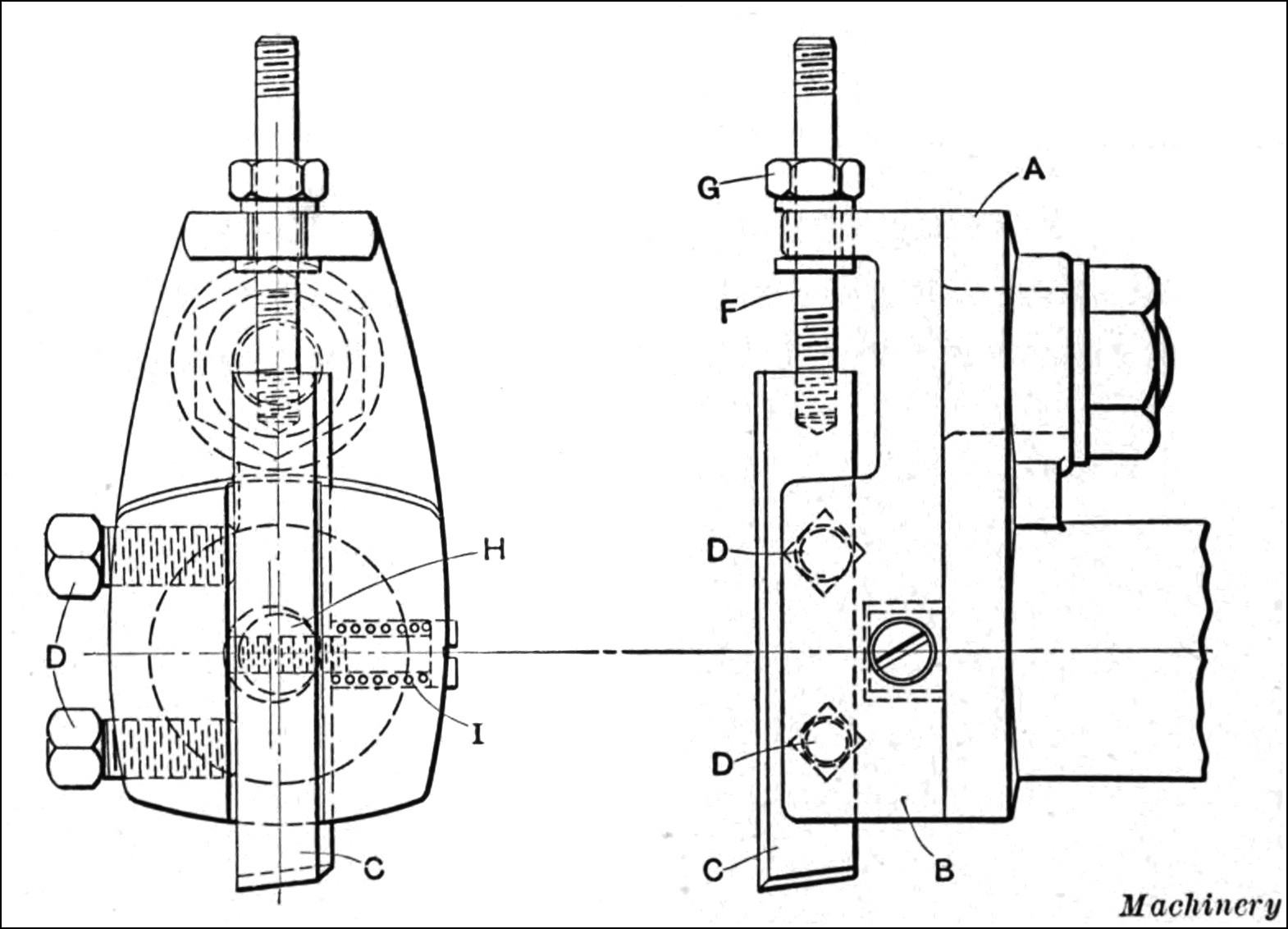
Fig. 16. Details of Relieving Turning Tool-holder shown in
Fig. 15
After these operations have been performed, the turret is indexed and the second face of the turret is brought in line with the chuck. This operation is accomplished with a relieving tool-holder E carrying a cutter e, which takes a cut 2¹⁄₂ inches along the body of the shell. An interesting feature of this tool is that on the return stroke of the turret it swivels back out of the way so that the shell is not scored by the tool dragging over it. The construction of this tool is more clearly shown in Fig. 16.
As is clearly shown in this illustration, the turret relieving turning tool comprises a shank on which is fulcrumed a tool-holding member B. This is slotted out to carry the turning tool C which is clamped in place by two set-screws D and is adjusted to turn the correct diameter by means of an adjusting stud and clamping nut F and G. The method of operating this tool is as follows: The fulcrumed tool-holder B is “held up” by means of a fillister-head screw, screwed into a stud H and acted upon by a coil spring I. A hole to receive the stud is drilled in the tool-holder B, allowing about ¹⁄₁₆ inch clearance. When the tool is in action it has a reverse position to that shown in the illustration, that is, the turning tool instead of being parallel with the center line is at a slight angle with it. In action, as soon as the turret advances, the tool comes into contact with the work, and the work, turning around, forces the cutting tool down and consequently depresses the spring, at the same time bringing the “lower part” of the hole into contact with the extended plug on the holder. In this way the tool is held rigidly and in contact with the work. As soon as the turret begins to move back, however, and the cutting pressure is released, the spring comes into action and throws up the tool, bringing it out of contact with the work.
Upon the completion of the operation which is accomplished from the second turret face, the turret is again indexed and the next operation is performed from the rear cross-slide and the third turret face. The third operation consists in cutting the grooves for the rifling band, and, on account of the under-cutting necessary, involves some interesting points. In order to hold the work rigidly while the grooving tools are acting on it, a revolving support F is brought in from the turret. The wide tool G for cutting the band grooves (this tool removes the greatest amount of the stock) is held on the rear cross-slide and is of the under-cutting type; that is to say, it operates under the work or tangentially instead of radially. Held on a bracket on the third turret face are two tools H and I, the purpose of which is to dovetail the rifling band grooves. These turret tools are held in a holder working in a slide on the bracket fastened to the turret face and are operated by a block held on the rear cross-slide. The action of these three tools, therefore, is simultaneous. The wide grooving tool, however, is slightly ahead of the dovetailing tools.
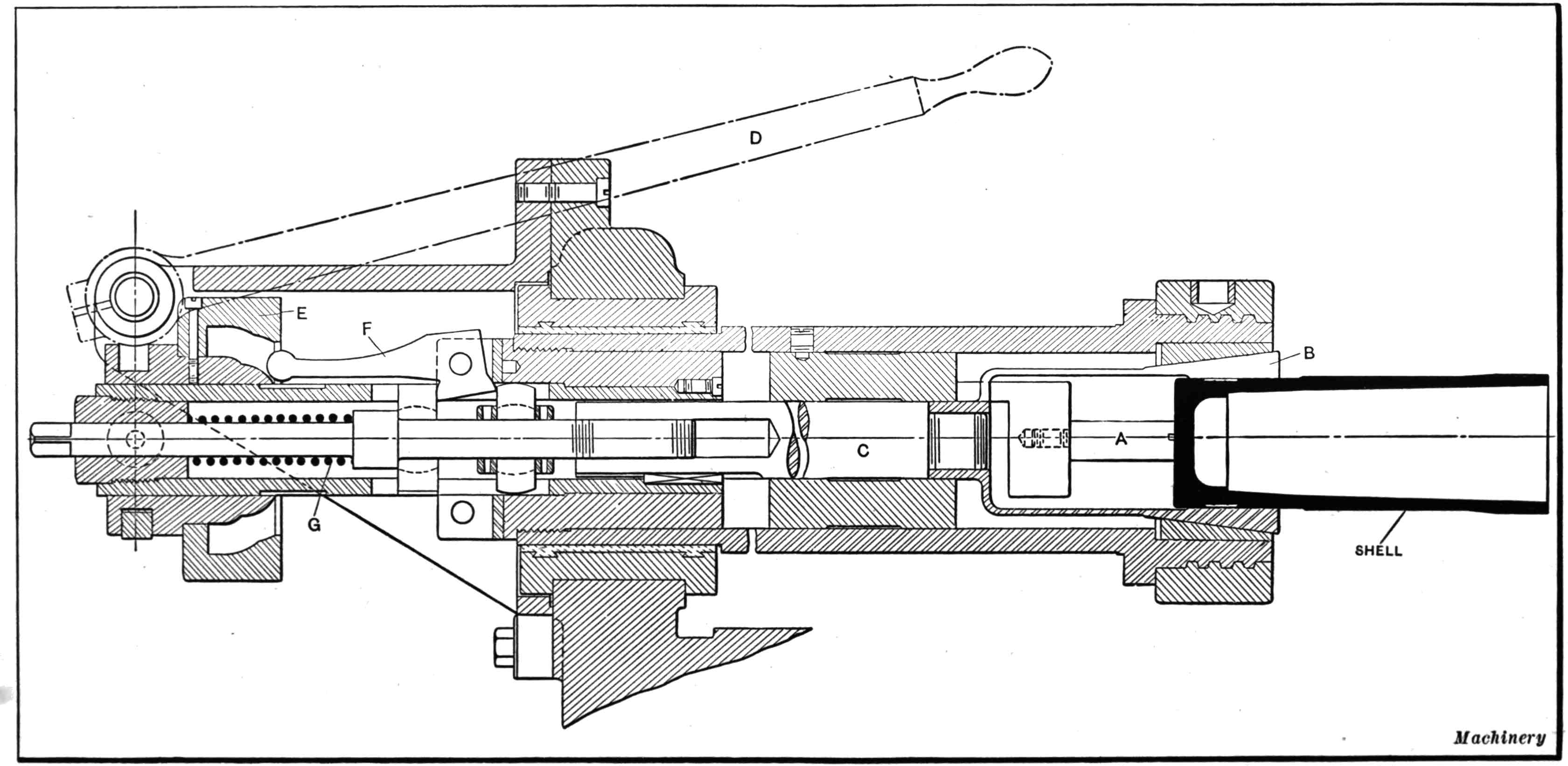
Fig. 17. Type of Draw-In Collet and Chucking Mechanism for holding Forged Shrapnel Shell for performing Second Series of Operations
The last operation is accomplished when the turret is indexed to the fourth position. Here, again, a roller support J steadies the work while the waving tool is in action on it. The two waves that are formed are for the purpose of preventing the rifling ring from turning, and they deviate about ¹⁄₁₆ inch laterally from being a true annular rib. The tool for cutting these ribs is shown at K and is of the forming type held in a dovetailed groove in the holder L. This also carries a roll M which contacts with the waved surface of the face-cam N, the curve of which gives the correct out-and-in motions to the waving tool K. The cam face is on a sleeve that is threaded onto the nose of the spindle of the machine, as is shown to the left of the illustration opposite the first turret face.
Method of Holding Shell for Second Operation.—The second series of operations on the shell is also performed on the Potter & Johnston automatic chucking and turning machine. The shell is held at the base end by a special collet of the draw-in type, as shown in Fig. 17. Fixed in the nose of the spindle is a positive stop A against which the shell is held by means of the draw-in collet B. This collet extends into the draw-in rod C, to which it is attached. The method of operating this gripping mechanism differs slightly from that shown in Fig. 14. In this case the spring collet B is drawn into a tapered sleeve to clamp it on the work. This is effected by means of lever D which is fulcrumed in a bracket extending from the rear bearing cap of the machine and operates a sliding cam sleeve E. The cam, in turn, operates fingers F, only one of which is shown, the latter acting upon the draw-in rod C to which the collet is attached. By depressing lever D, the chuck is opened by means of the coil springs G which act upon the draw-in rod C when the pressure of the fingers has been released. Lifting up handle D closes the chuck, and depressing it opens the chuck.
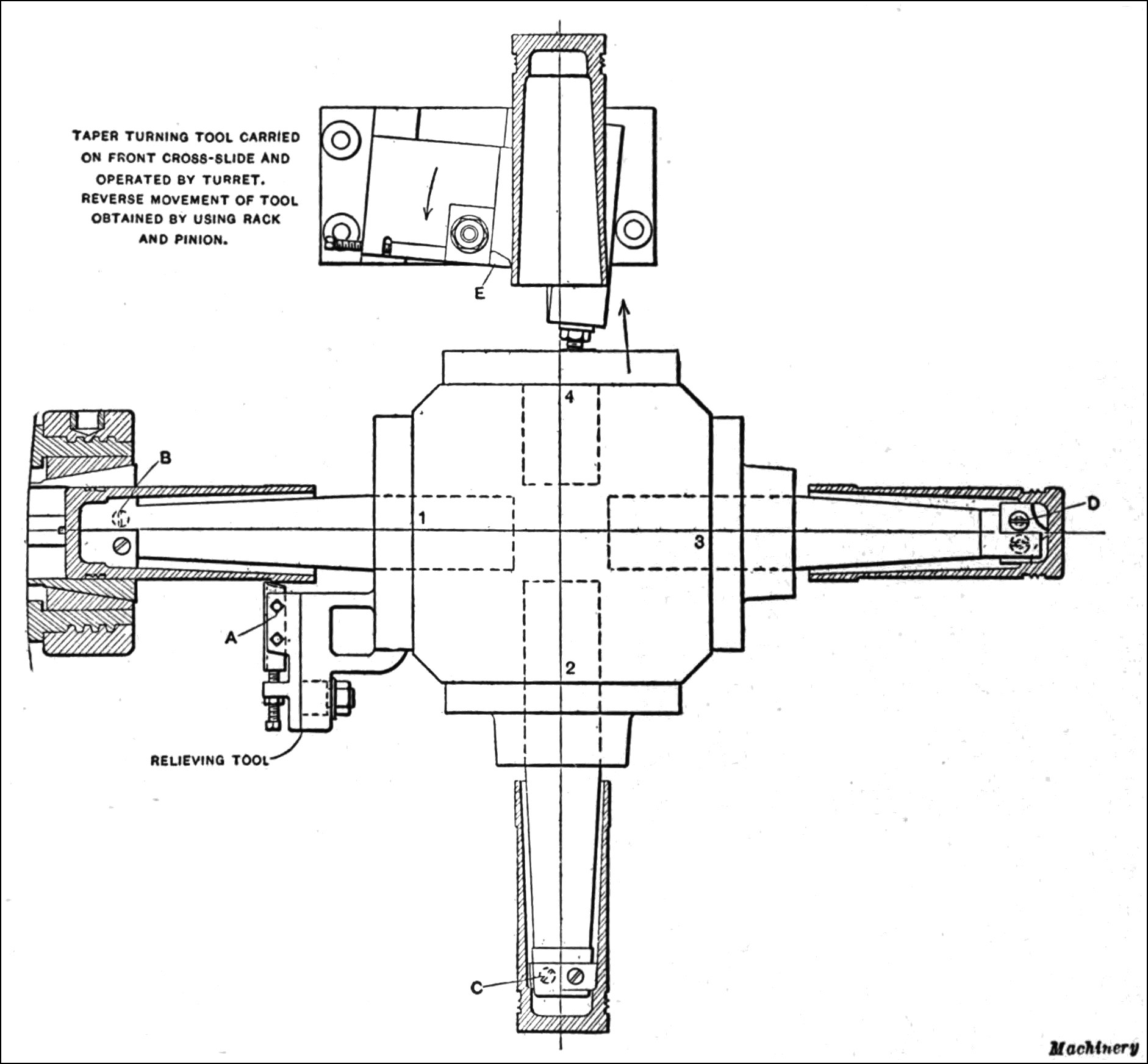
Fig. 18. Tooling Equipment used on No. 6A Potter & Johnston Automatic Chucking and Turning Machine for performing Second Series of Operations on Forged Shrapnel Shell
Second Series of Machining Operations on Shrapnel Shells.—The operations on the shrapnel shell performed in the second setting are shown in Fig. 18. The relieving tool A, held on the first face of the turret, covers that section of the shell which in the former operation was held in the gripping jaws. While this cut is being taken, a turret tool B rough-bores the powder pocket and diaphragm seat. The relieving tool A is constructed and operated similarly to the relieving tool described in connection with Fig. 16. It will be noted here that the threads on the spindle nose are protected by a cast-iron cap to prevent them from being injured. Upon the completion of the operation just described, the turret is indexed, bringing the second face in line with the spindle. Here the diaphragm seat is finished with a flat cutter C, which is held in the boring tool illustrated. The turret is again indexed into the third position, where the powder pocket is finished by means of the flat cutter D.
The turret is now indexed to bring the fourth face in line with the spindle where the extreme open end of the shell is turned taper by means of a tool E that is carried on the front cross-slide and operated by the turret. By referring to this illustration, it will be noticed that the taper is turned from the spindle toward the outer end of the shell and is, therefore, a reverse turning operation. The tool is caused to move toward the turret by using a rack and pinion to reverse the movement. On this operation, as well as on the previous one, one man takes care of four machines.
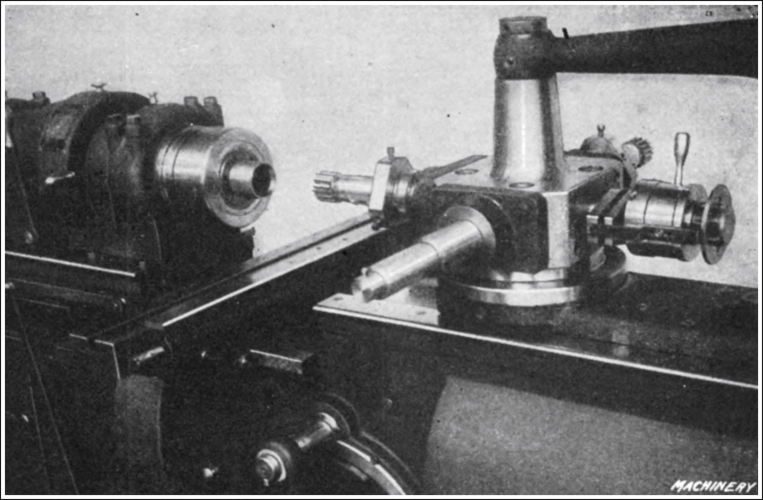
Fig. 19. Machining Inside of Shrapnel Shell, and threading with Automatic Collapsible Tap on Potter & Johnston Automatic Chucking and Turning Machine
Third Machining Operation on Shrapnel Shells.—Before any other machining operations are done on the shell, it is taken to a lead bath where it is heated and afterward placed under a press which closes in the nose or open end of the shell. For machining in the third operation, the shell is held practically in the same manner as for the second operation, except that it is gripped farther along the body. The machining performed in this operation is as follows: On the first turret face, rough-bore and finish-bore for a distance of 1 inch from the end of the shell; second turret face, rough-bore the inside of the shell for a distance of 1 inch back from the thread; third turret face, finish-form on the inside for a distance of 1 inch back of the thread; and fourth turret face, thread with a collapsible tap. The various machining operations on the 3-inch size of shrapnel shells are performed on a standard Potter & Johnston 6A automatic chucking and turning lathe. It is recommended that these machines be run in batteries or units of seven each, four machines being set up for the first operation, two machines for the second operation, and one machine for the third operation.
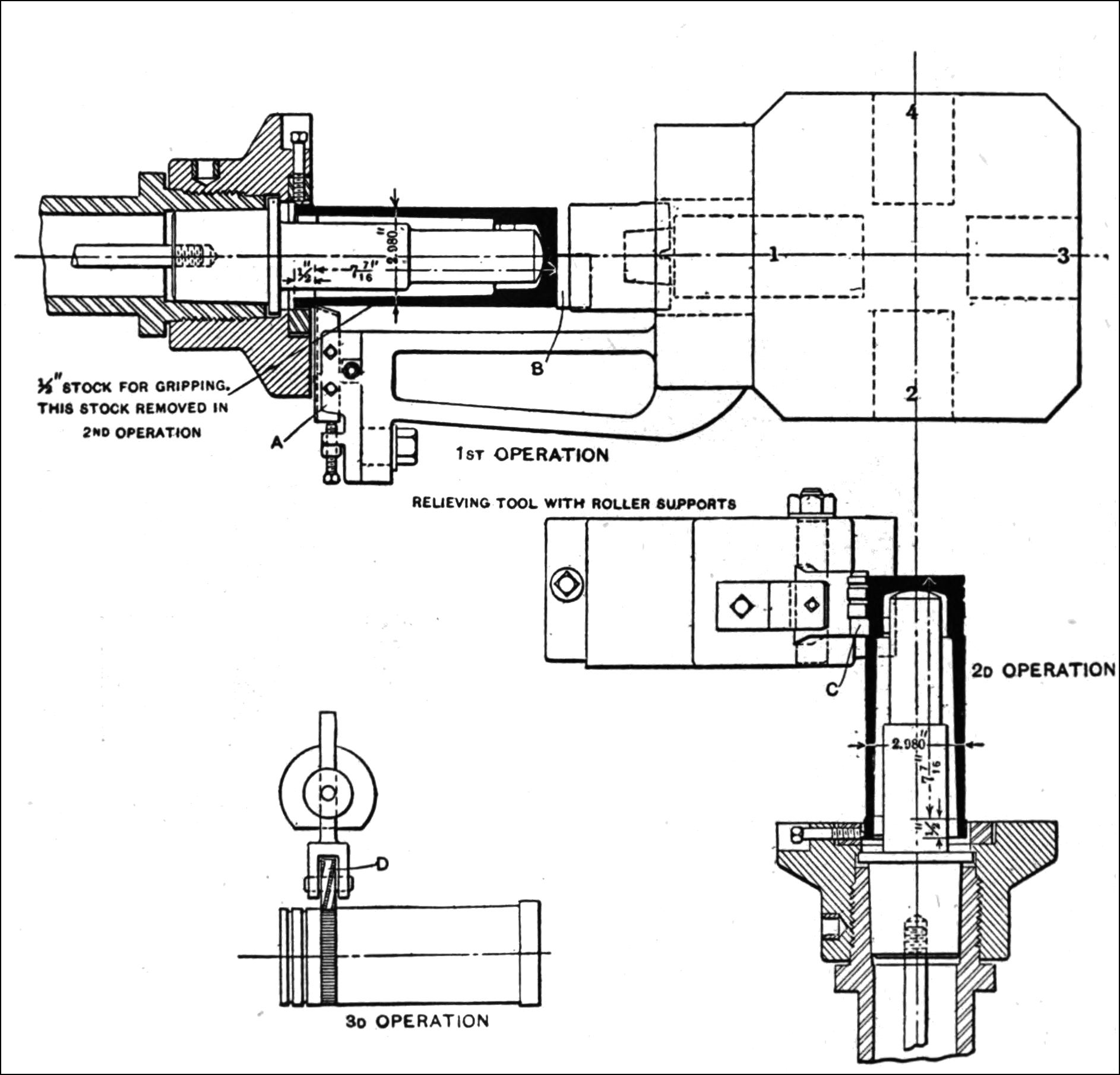
Fig. 20. First Series of Operations on “Frankford” Shell on a Potter & Johnston 6A Automatic Chucking and Turning Lathe
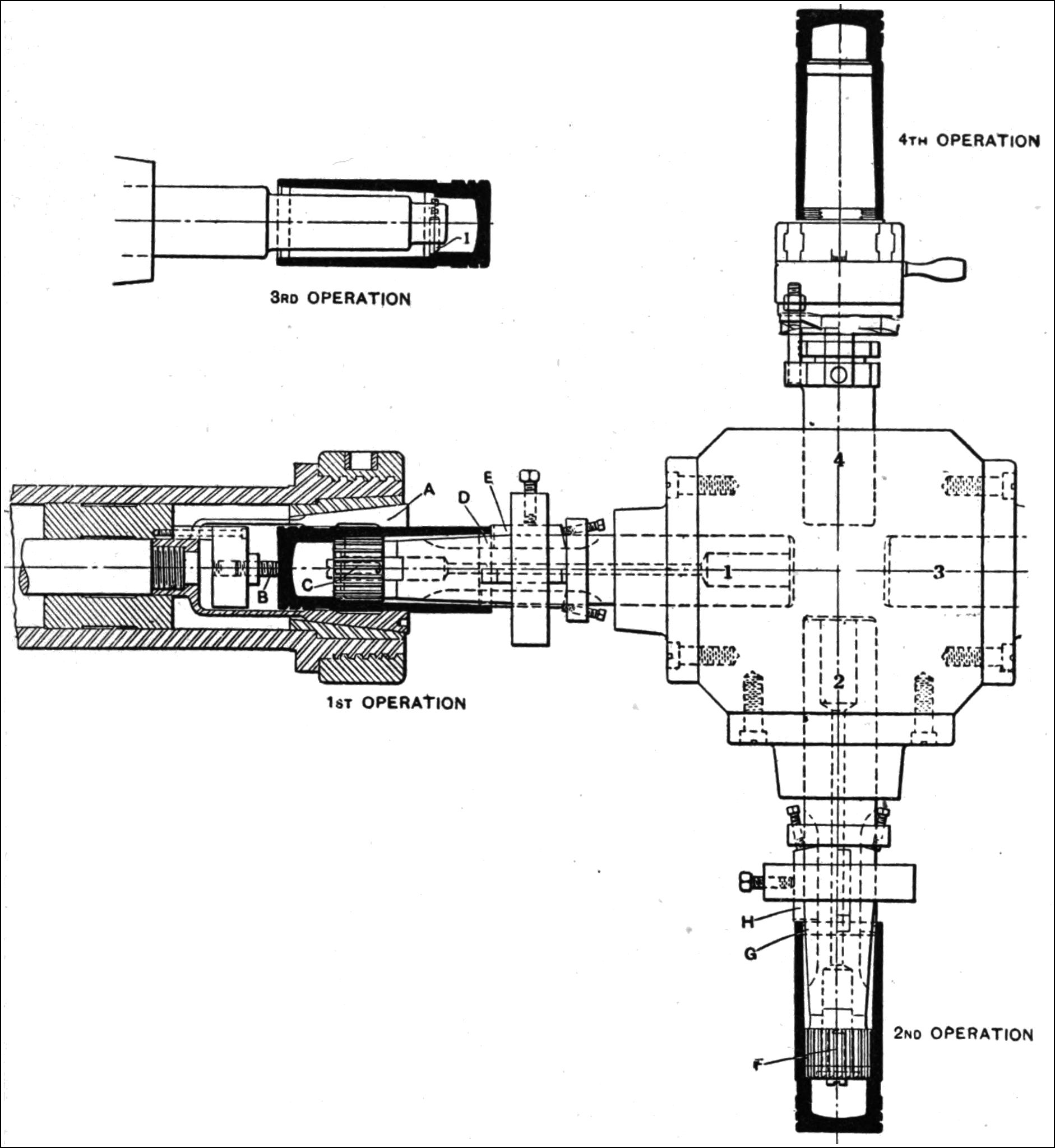
Fig. 21. Second Series of Operations on “Frankford” Shell on Potter & Johnston Automatic Chucking and Turning Lathe
Machining “Frankford” Forged Shell.—The machining of the American or “Frankford” 3-inch type of high-explosive shrapnel shell is comparatively easy, inasmuch as there is no nosing to be done, and the entire shell may be machined at two settings. Fig. 20 shows the way in which the first operation is taken care of on the No. 6A Potter & Johnston automatic chucking and turning lathe. The forged shell is held on an expanding arbor of the same type as that shown in Fig. 15. In the first turret position, the operations consist in taking a straight cut across the diameter and facing off the end. The external turning tool A is of the relieving type, and B is a facing tool that works on the end. Both of these tools are supported and operated from the turret. A roll support, not shown, steadies the work while tool A is working. The turret now backs out, and a forming tool, held on the cross-slide, advances, cuts the rifling band and the semicircular grooves in the end of the shell, and at the same time chamfers the corner. Knurl D, held on the rear of the cross-slide, is then advanced. This knurls the bottom of the rifling band groove.
By referring to Fig. 20, it will be seen that the grooves do not extend entirely across the face of the knurl, but instead two “knurl” ribs similar to a double thread are formed on the periphery. This construction makes it possible to sink the knurl into the work to the proper depth without exerting excessive pressure on the arbor and throwing it out of line.
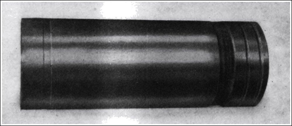
Fig. 22. Three-inch Shrapnel Shell made on a Gridley Automatic Turret Lathe
Second Series of Operations on “Frankford” Forged Shrapnel Shell.—For the second series of operations, the “Frankford” shrapnel shell is held in a draw-in collet as shown in Fig. 21. As the shell has been completely machined on the outside, it is let into the collet for a considerable distance. For machining, it is shown gripped in the collet by jaws A and is backed up by positive stop B. At the first turret face, tool C rough-bores the diaphragm seat, tool D bores the thread diameter, and tool E faces and chamfers the end. The turret is now indexed, and tools F, G, and H perform similar finishing cuts. A holder held on the third turret face carries tool I that chamfers the powder pocket, and at the fourth turret face a collapsible tap threads the open end.
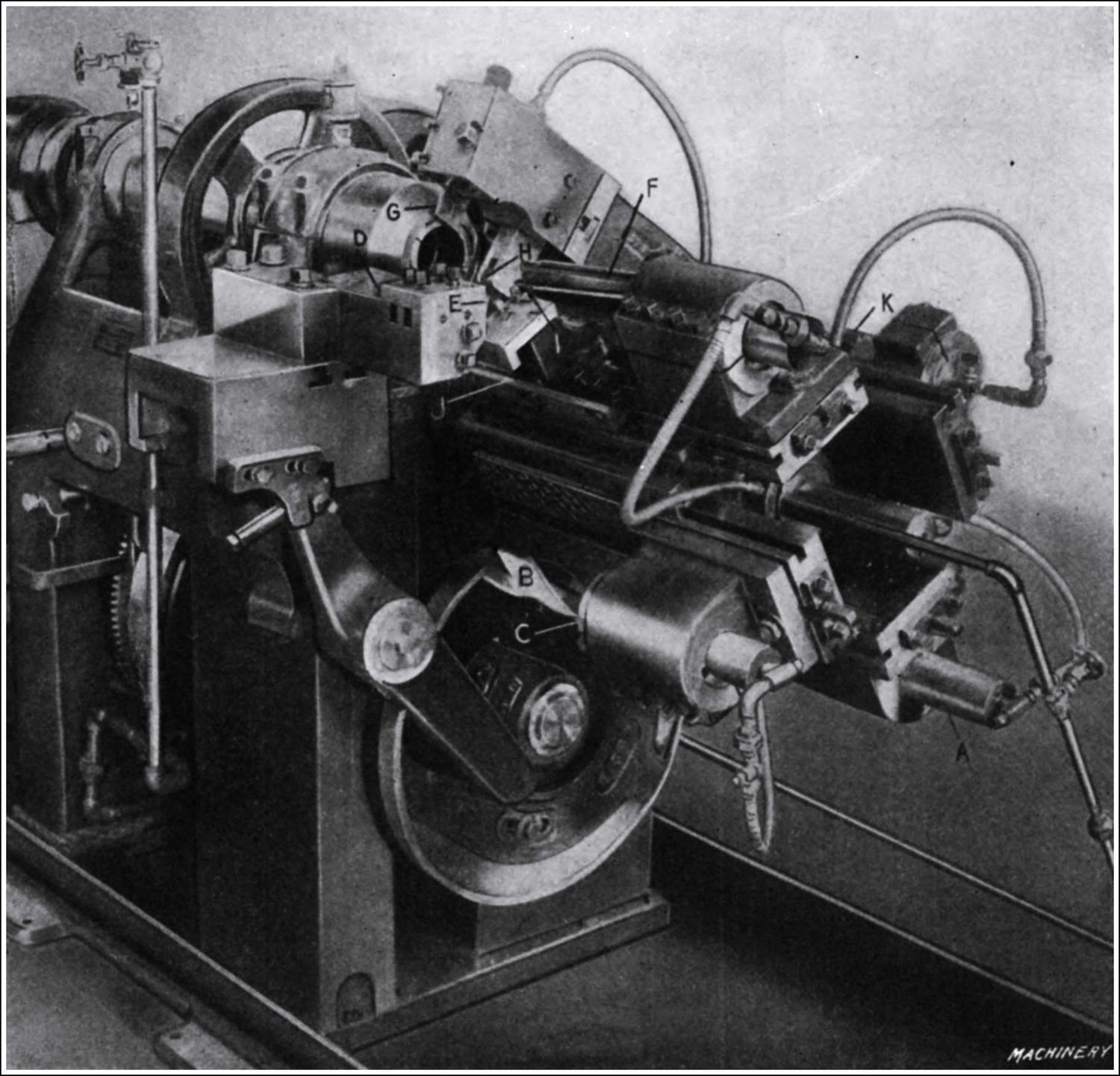
Fig. 23. Tool set up for Producing the Shell shown in
Fig. 22
Making Shrapnel Shells on the Gridley Automatic Turret Lathe.—Figs. 22 to 25 show a three-inch shrapnel shell made on the 3¹⁄₄-inch Gridley single-spindle automatic turret lathe. The steel from which the shell is made is very tough. The specifications are from 125,000 to 135,000 pounds tensile strength, 110,000 pounds elastic limit, a twenty-five per cent reduction of area, and a twelve per cent elongation. It will be seen from the above specifications that the steel is, of necessity, very tough and difficult to work; in addition, a large taper reamer must be used, and the outside of the shell must be relieved throughout the central portion. It is also necessary to machine the piece to extremely accurate dimensions, all of which tends to make the work still more difficult. Fig. 22 shows a view of the shrapnel shell. It is approximately three inches in diameter and eight inches long, and the limits allowed for the sizes are extremely close throughout, both inside and outside. Figs. 24 and 25 show the successive steps employed in machining the piece complete, the four views presented representing the appearance of the work and the operations performed at each indexing of the turret. Fig. 23 will enable the operation of the different parts to be more clearly understood.
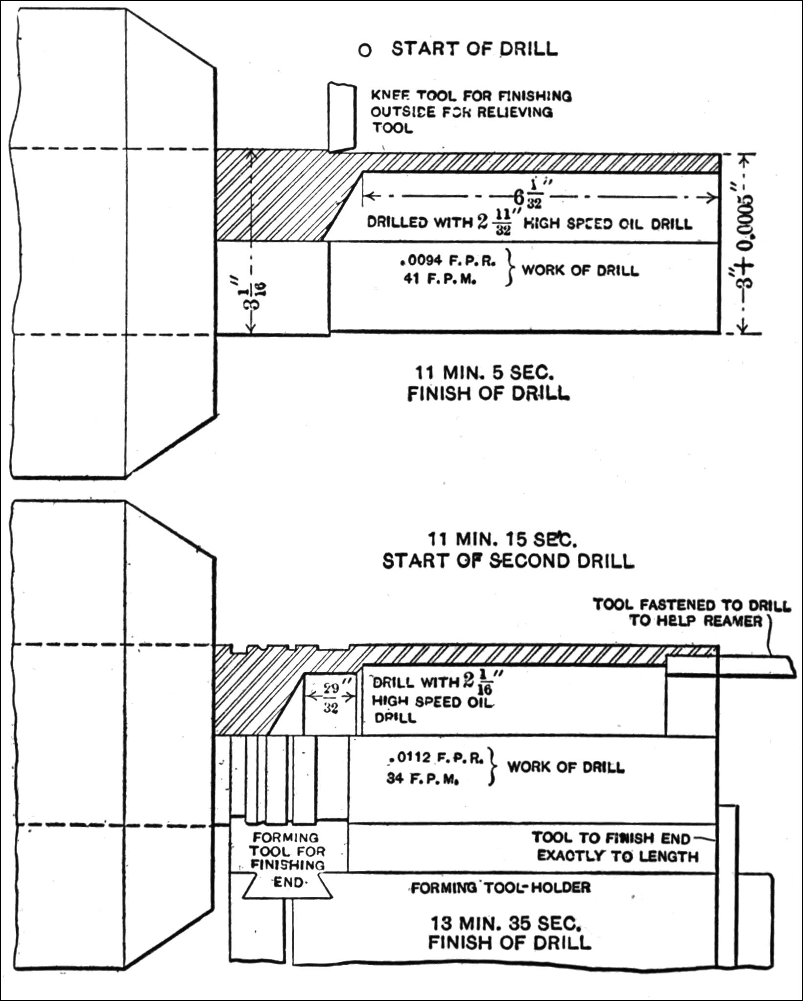
Fig. 24. Successive Steps and Operations employed in Making the Shell shown in
Fig. 22
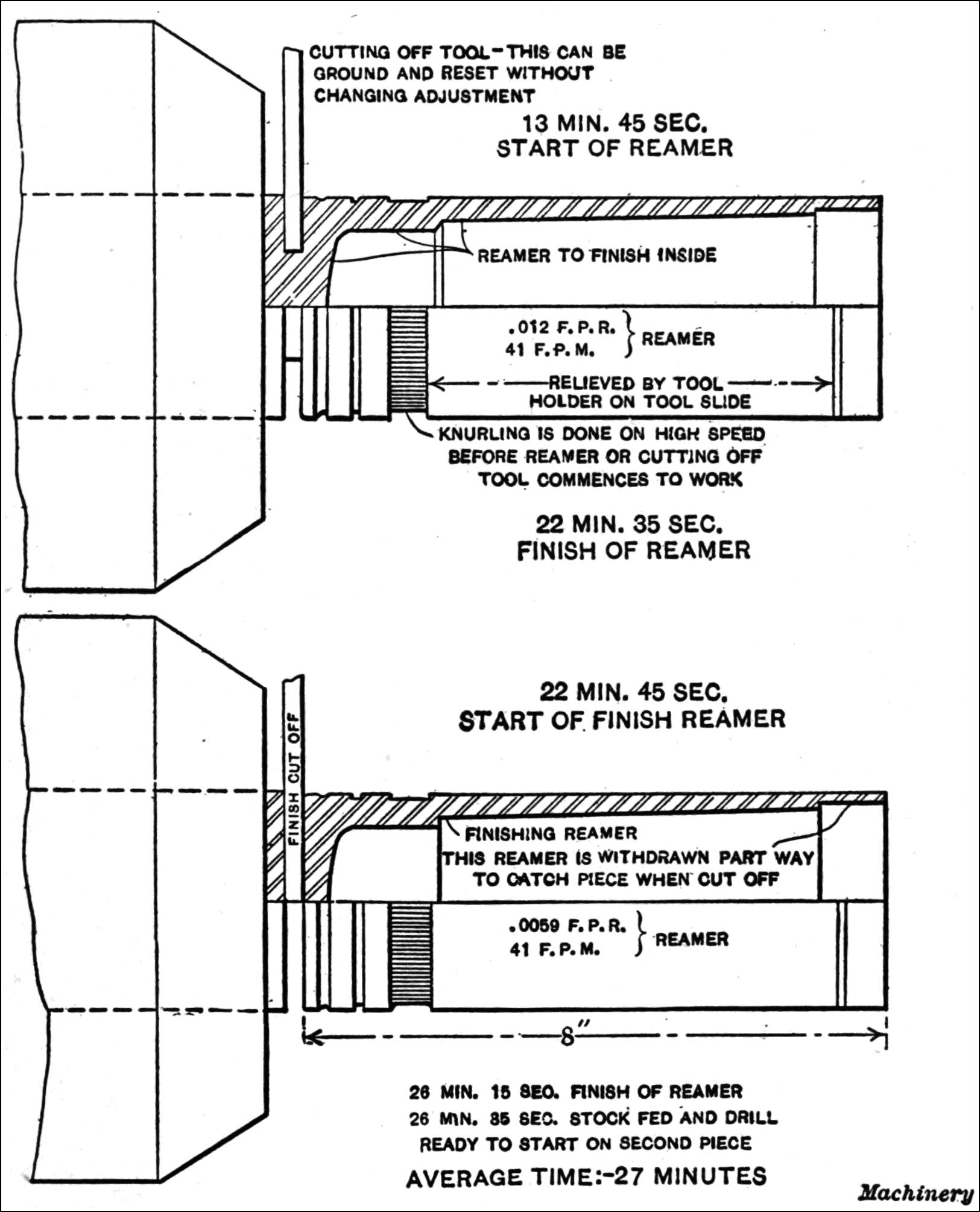
Fig. 25. Successive Steps and Operations employed in Making the Shell shown in
Fig. 22
While the operation of the Gridley automatic turret lathe is generally understood by mechanics, it may be well to state briefly the general principles upon which work is done in the single-spindle machine. In this type of machine, the position of the work does not change as it does in the multiple-spindle machine, but the turning is accomplished by the operation of tools mounted on tool-slides which, in turn, work on a turret that revolves about a horizontal axis, successively presenting the tools for operation upon the work. This will be readily understood by glancing at the illustration Fig. 23. It will also be noticed from this illustration that the forming tools and cutting-off tools are operated from a face-cam at the lower part of the machine. The forming slide is actuated by a cam groove cut in one side of the cam-plate while the cutting-off slide receives its movement from a cam groove on the reverse side of this plate.
At the first position of the turret, a large 2¹¹⁄₃₂ inch high-speed oil drill is run into the bar to a depth of 6¹⁄₃₂ inches, and, at the same time, a knee-turner located on the tool-slide turns the outside of the stock, thereby removing the scale from the bar. Referring to Fig. 23, which shows the turret in the third position, the end of this large drill is shown at A, and, of course, when at work, it would be in the position of the reamer which is shown at F. The time elapsed at the completion of this part of the work is eleven minutes, five seconds.
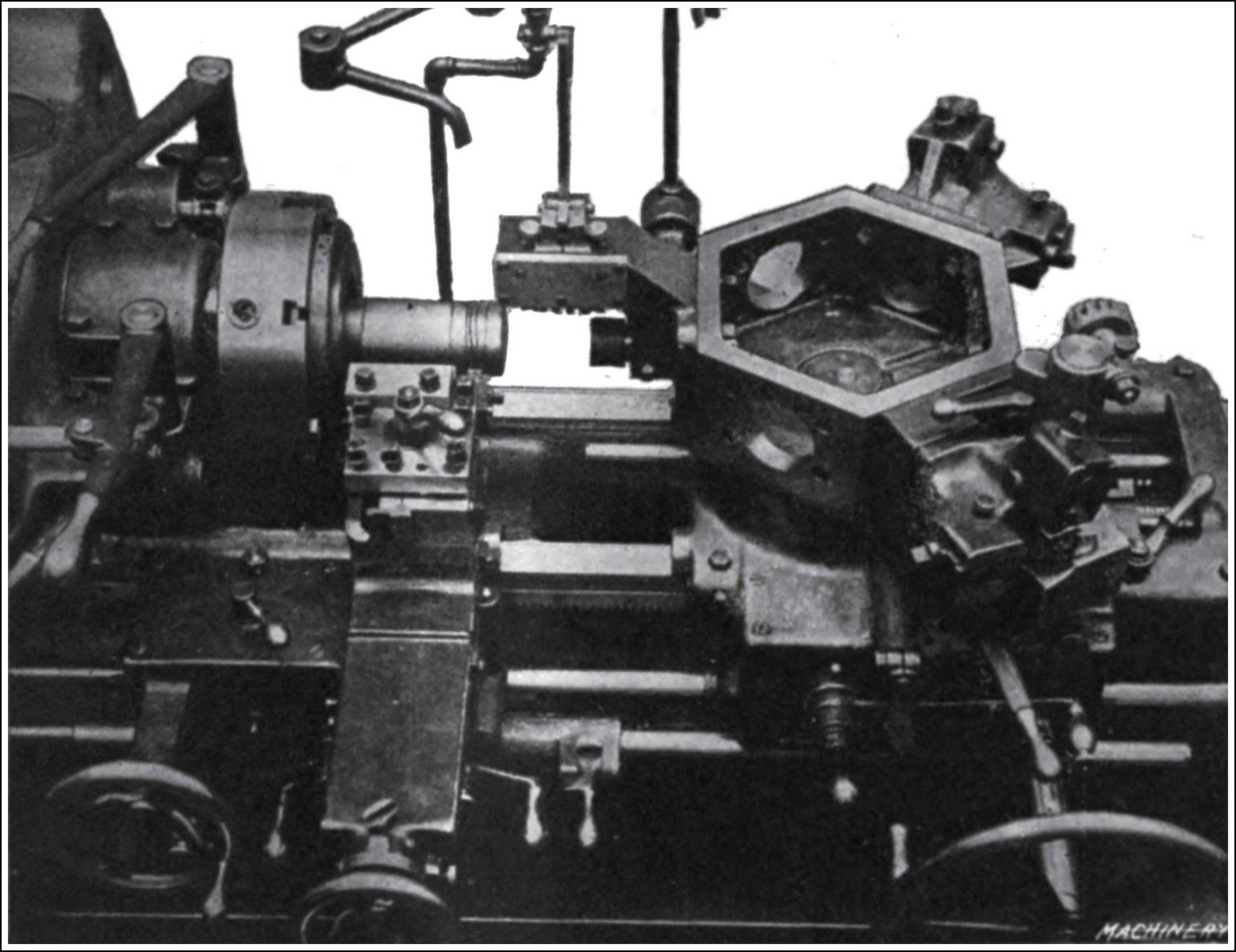
Fig. 26. First Chucking on Warner & Swasey Turret Lathe for machining British Forged Shrapnel Shells
At the second position of the turret, a smaller drill, 2¹⁄₁₆ inches in diameter, which is shown at B, is run in at the bottom of the hole previously drilled to a depth of ²⁹⁄₃₂ inch. At the same time a counterboring tool, which is located at C and which is attached to the drill with a set-screw, is at work counterboring the end of the hole in the shell. During the time that this drilling and counterboring operation is being performed, the forming tool shown at D is being fed into the outside of the head of the shell, finishing the three grooves as shown; in addition, a sizing tool E, which is at a fixed distance from the forming tool, comes in and sizes the work to exactly the right length. The time elapsed up to the finishing of this part of the work is thirteen minutes, thirty-five seconds.
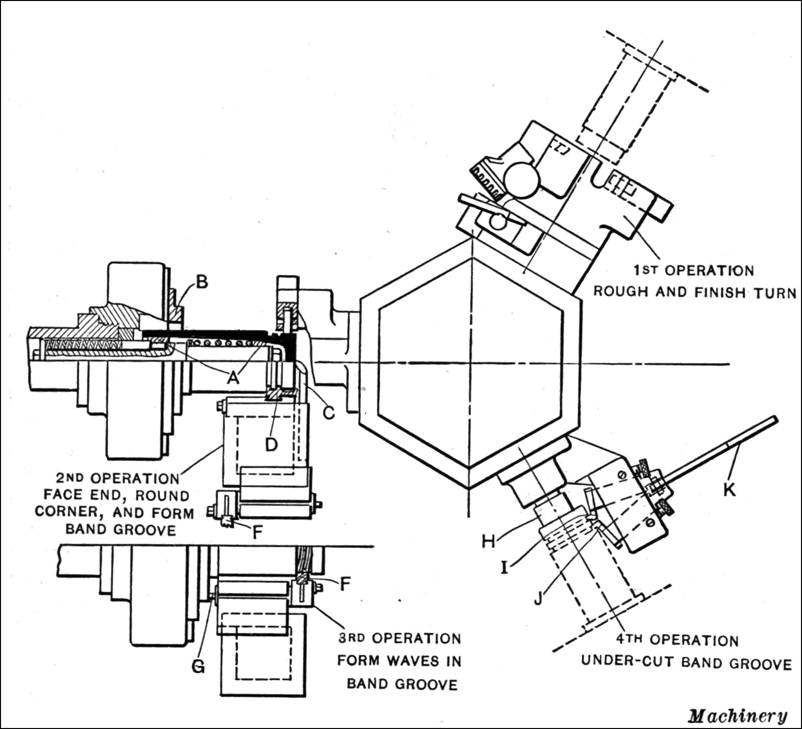
Fig. 27. Diagram Illustrating Position and Relation of Tools for First Chucking on British Forged Shell
At the third position of the turret, which, by the way, is the one shown in Fig. 23, the large taper reamer F is run in, which operation removes the bulk of the stock for the taper, and a second step at the end of this reamer finishes the extreme end of the hole at the bottom of the shell. The blades of this reamer are nicked to break the chips as they are being formed. Before the reamer begins to cut, the knurling tool H is brought against the work (while it is on the high speed) by the cutting-off slide, which, of course, results in a better knurled section than would result if the knurling of the piece were done at a lower speed. During the reaming operation, the cutting-off tool G is run in part way to facilitate the final severing of the piece. In addition, the relieved part of the work is turned by a tool mounted in a tool-holder on the slide of the turret. This tool is shown at I and it is operated by a templet J which has a raised projection that throws the tool into the work after it has reached the right position with relation to the length of the shell. The total time elapsed up to the finishing of this part of the work is twenty-two minutes, thirty-five seconds. At the fourth and last position of the turret, a finishing reamer sizes the outer end of the interior of the shell and is withdrawn but part way, so that, when the cutting-off slide comes in and finishes severing the piece, the shell is caught on the reamer and not allowed to drop and possibly be injured by so doing.
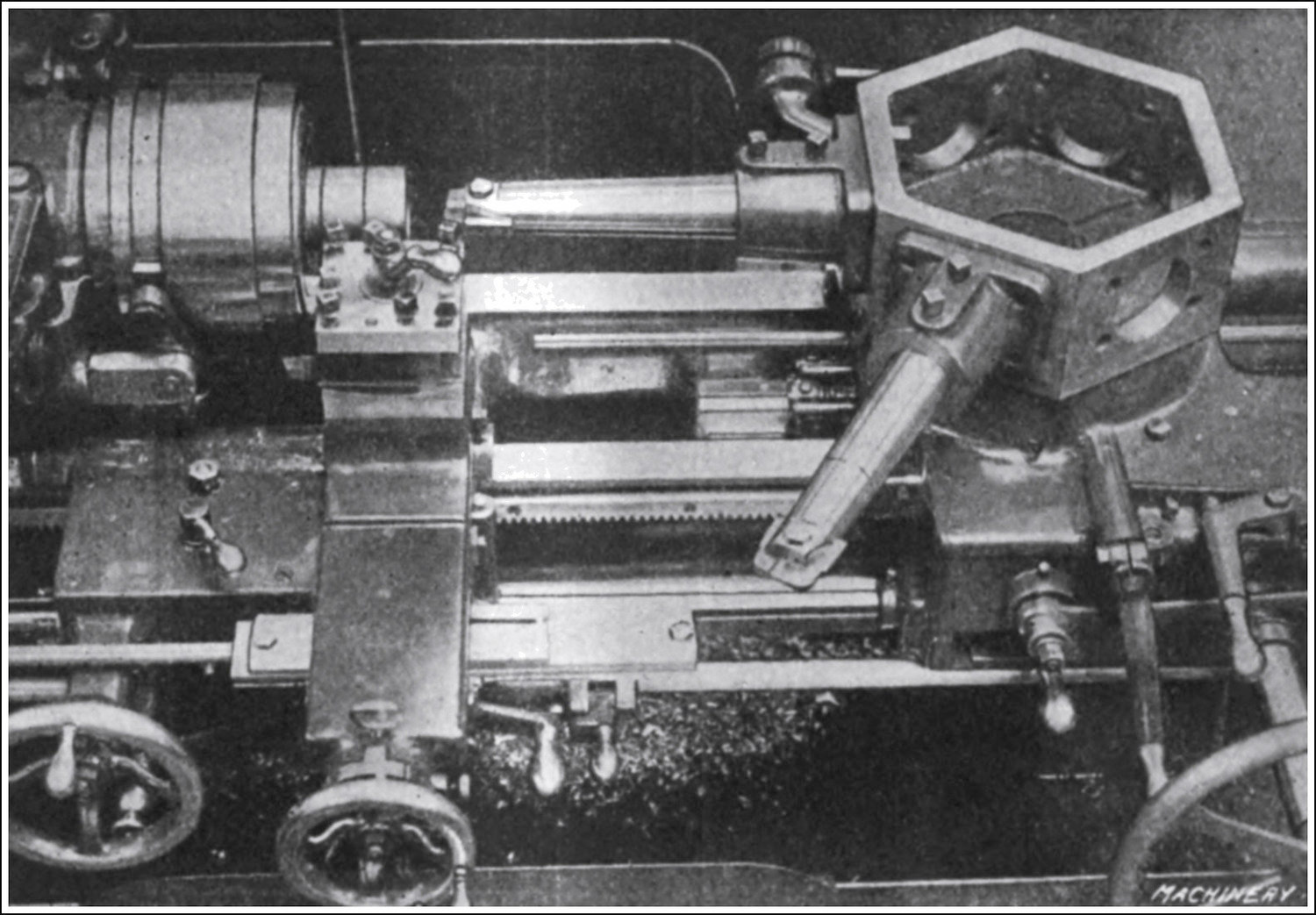
Fig. 28. Set-up on Warner & Swasey Turret Lathe for Second Series of Operations on Forged Shrapnel Shell
The average total time for making this piece complete is twenty-seven minutes. On account of the rigidity of the tool support, the tools do not require sharpening more often than once for fifty pieces, with the possible exception of the cutting-off tool, which must be sharpened after about half that number of pieces have been completed.
Using Warner & Swasey Turret Lathe for Machining Forged Shrapnel Shells.—In Fig. 26 is shown a typical set-up on a Warner & Swasey No. 2A universal hollow-hexagon turret lathe for machining an 18-pound shrapnel shell forging. The arrangement of the various tools for performing the first series of operations is more clearly illustrated in Fig. 27, to which reference should now be made. The forging is located for machining on a special arbor fitted into the spindle and carrying two spring-controlled centering bushings A. These serve to locate the shell, which is then gripped by the floating jaws of the chuck on the external diameter, and a stop on the end of the arbor locates the shell from the bottom of the powder pocket.
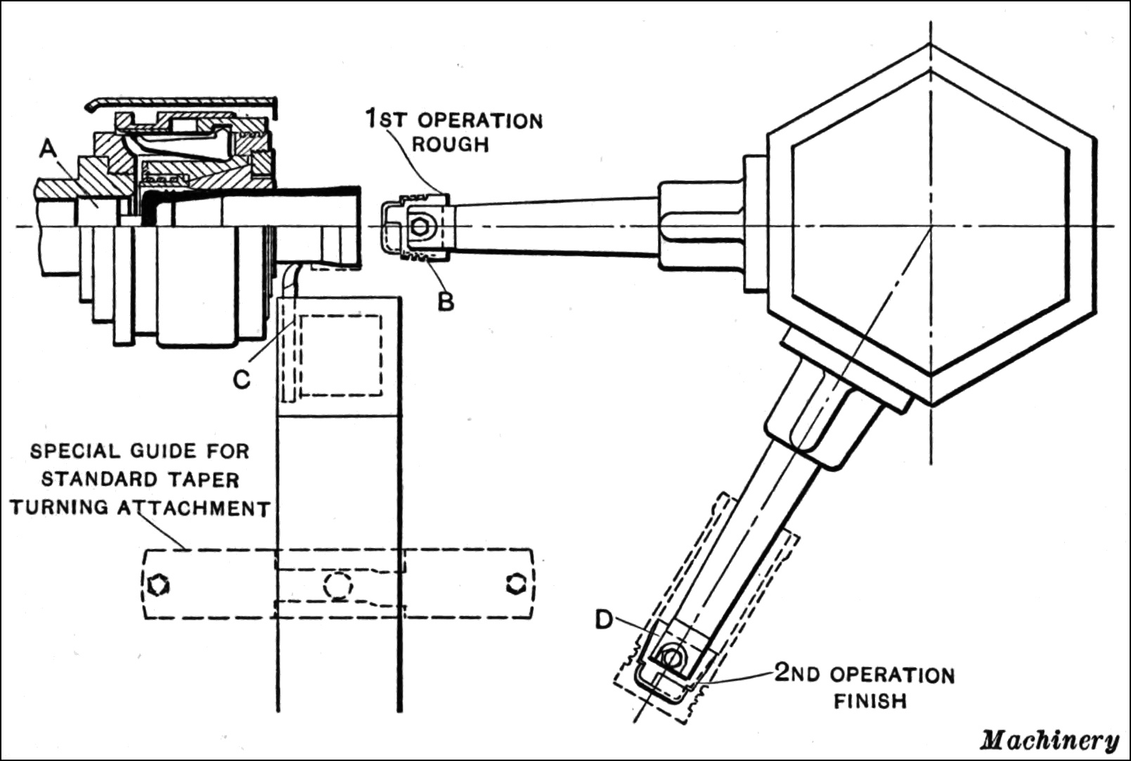
Fig. 29. Diagram Illustrating Sequence of Operations performed at Second Chucking
The first operation consists in taking a cut from the external diameter with a special box-turner provided with a roll steadyrest and carrying two turning tools. The second operation is handled from the cross-slide, the shell forging meanwhile being supported by a roll steadyrest clamped to the turret. In this operation the closed end of the shell is faced with tool C, the corner rounded, and the band groove formed with forming tool D. The third operation—first chucking—is performed with tool F which produces the waves in the band groove, and is operated in the following manner: Referring to the lower left-hand corner of the illustration, it will be seen that a roll G is brought in contact with the face-cam B, thus giving the desired oscillating movement to the waving cutter. The fourth and final operation consists in under-cutting the band groove with a tool clamped to the turret. This tool gages from the end of the shell by a revolving stop H, and is provided with two slides, set at the desired angle to each other and the work, carrying under-cutting tools I and J. These slides are operated by handle K.
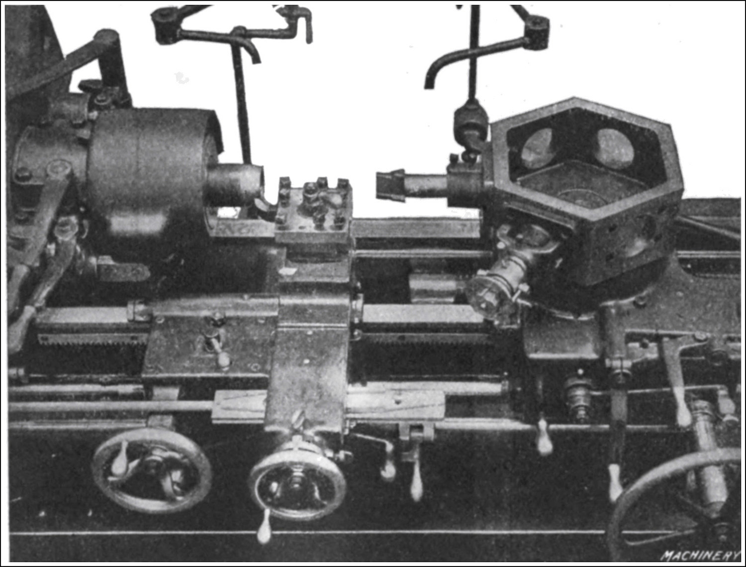
Fig. 30. Third Chucking Set-up on British Forged Shrapnel Shell
The second chucking on this shell is handled as shown in Figs. 28 and 29 on the same type of machine. As shown in Fig. 29, the shell for this operation is gripped in an automatic chuck, and a stop A for locating it is held in the spindle. The first operation consists in roughing out the powder pocket and diaphragm seat with a cutter B, and rough-turning that portion of the shell held in the chuck in the previous chucking with a tool C. This tool is held in the cross-slide toolpost, and is controlled in its movement by a special guide fastened to the regular taper-turning attachment. The second operation finishes the powder pocket and diaphragm seat with a cutter D.
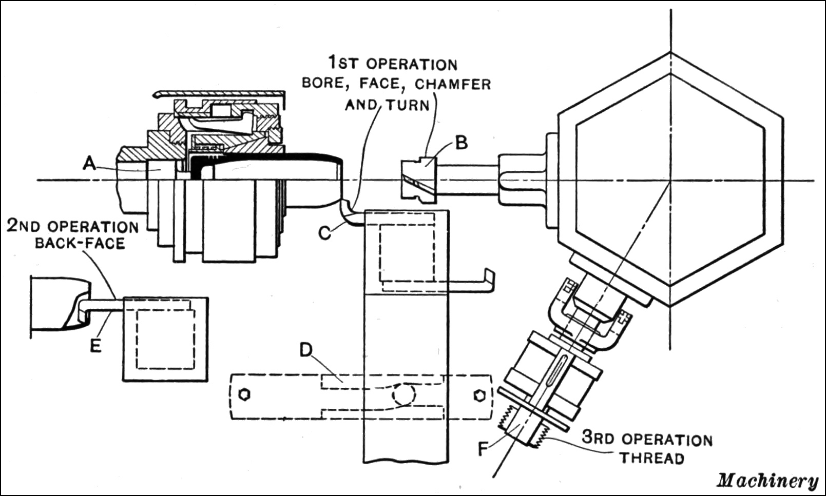
Fig. 31. Diagram Illustrating Relation of Tools for performing Third Series of Operations
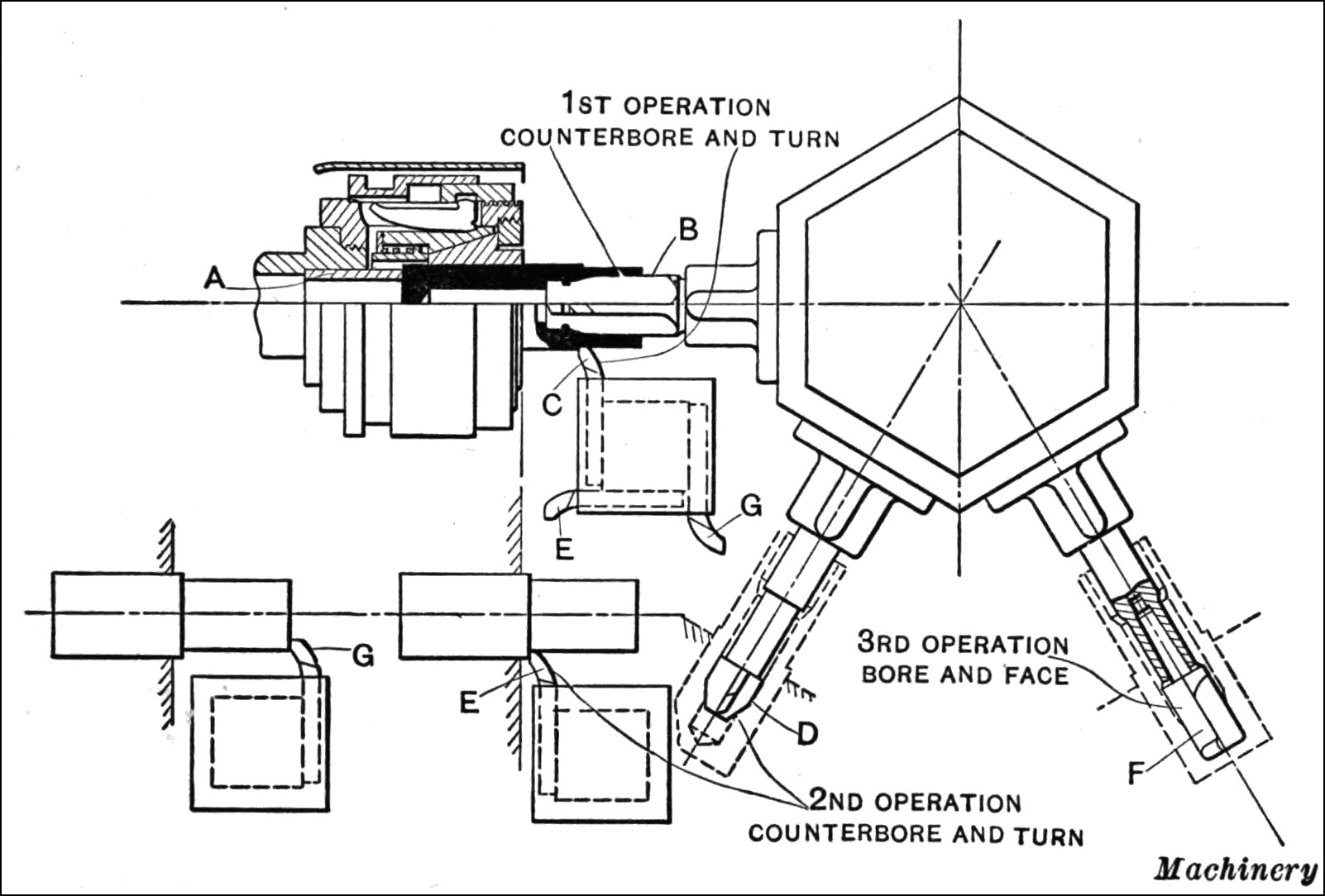
Fig. 32. First Chucking on French Shell made from Bar Stock on Warner & Swasey Turret Lathe
After the second chucking, the shell is heated on the nose, closed in and is then brought back to the turret lathe, when the operations are performed as shown in Figs. 30 and 31. Here, again, the forging is held in the automatic chuck and is located by a plug A in the spindle. The first series of operations consists in boring, facing and chamfering the nose with a counterbore B, and at the same time turning the external radius on the nose with a tool C. Tool C is held in the cross-slide square turret and is controlled in its movement by a special guide fitting on the regular taper-turning attachment.
The second operation, shown to the left of the illustration, consists in machining the radius inside the nose with a tool E, controlled in its movement by the special guide D, as previously mentioned. The third and final operation consists in cutting the thread with a collapsible tap F.
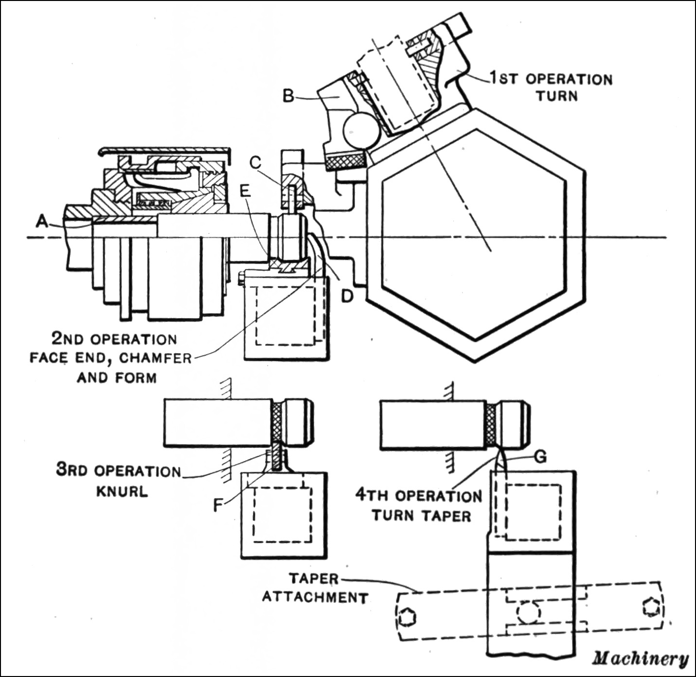
Fig. 33. Second Chucking on French Shrapnel Shell
Using Warner & Swasey Turret Lathe for Machining Bar-stock Shrapnel Shells.—The method of machining shrapnel shells from bar stock differs somewhat from that used for forgings, and is handled on a No. 2A universal hollow-hexagon turret lathe. In this particular case, the shell blank, previous to machining in the turret lathe, is rough-drilled in a high-powered drilling machine to the bottom of the powder pocket. Assuming that this has been accomplished, the operations for the first chucking are then carried on as illustrated in Fig. 32. Here the shell is held in an automatic chuck and is located by a stop A. The first operation consists in counterboring the mouth with the counterbore B, and rough-turning the external diameter with tool C; second, counterboring with the cutter D and turning further along the shell with a tool E; third, finishing the bottom with a cutter F and facing the end of the shell with a tool G.
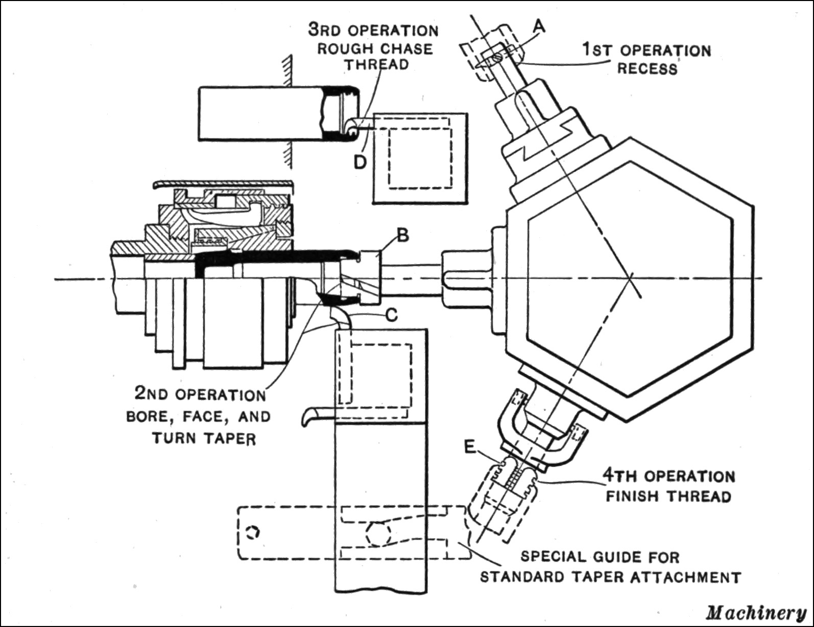
Fig. 34. Third and Final Chucking on French Shrapnel Shell
In the second chucking, the operations shown in Fig. 33 are performed. Here the shell is reversed in the automatic chuck and is located, as before, by a stop A. The first operation consists in turning that portion of the body held in the chuck in the previous chucking with a roll-supporting turning tool B. Second, supporting the shell with a roller support C held on the turret, facing the end with a tool D, and chamfering the band groove and the end with a cutter E held on the cross-slide square turret. The third operation is to support the shell from the turret, knurling with a knurl F from the cross-slide square turret. Fourth, taper-turn from the end to the band groove with a tool G, guided by the taper-turning attachment.
For the third chucking, the shell, as indicated in Fig. 34, is held in the same manner as for the first chucking. First, it is recessed with a tool A and brought into action by operating the special holder which has a cross-sliding movement; second, it is bored and faced with a counterbore B from the turret, and taper-turned with a tool C operated by a special guide from the taper-turning attachment. In the third operation, the thread in the nose is rough-chased with a tool D, controlled in its movement by the chasing attachment of the machine; fourth, the thread is finished with a tap and tap-holder E.
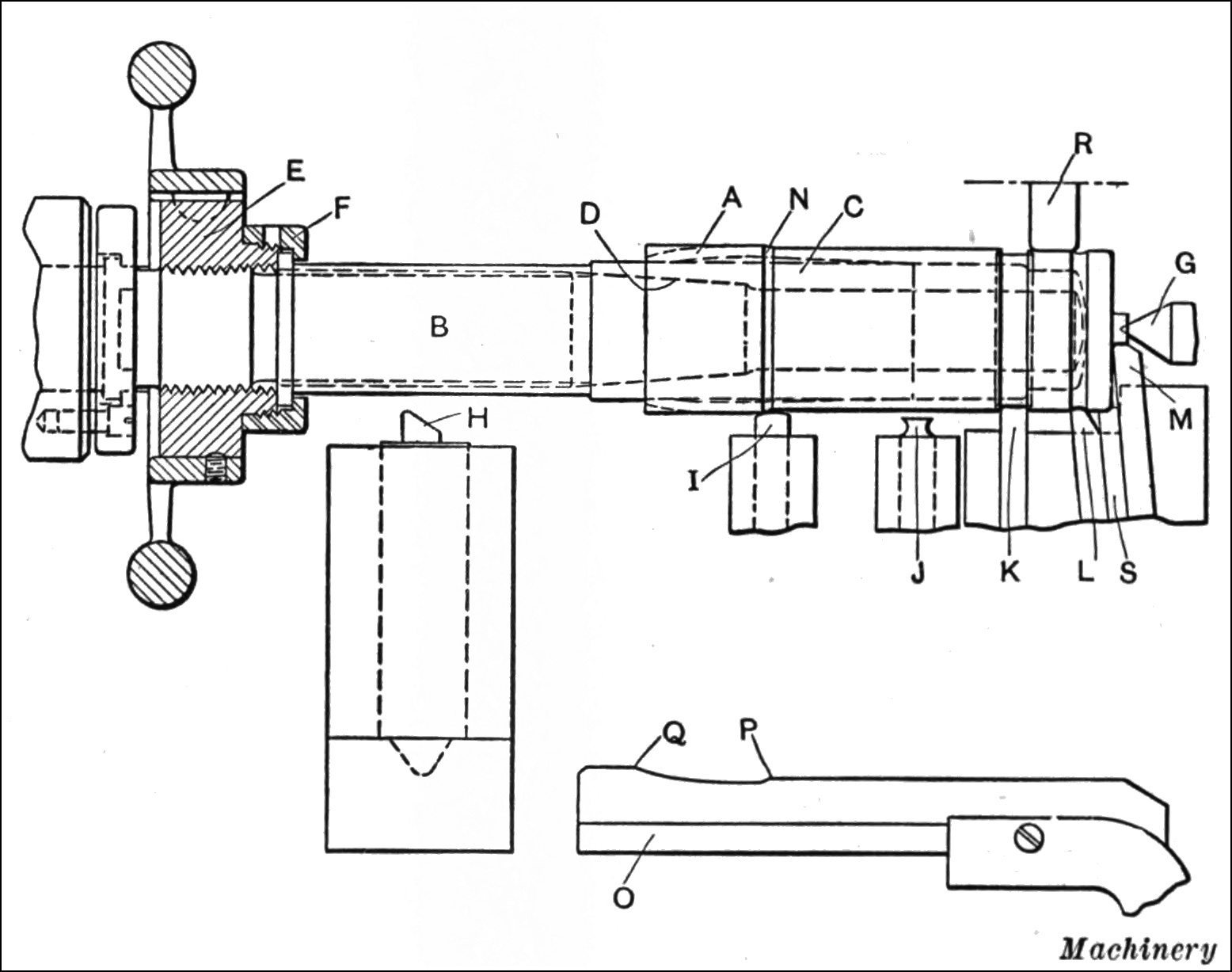
Fig. 35. Diagram showing Method of holding and performing First Series of Operations on Forged Shells on “Lo-swing” Lathe
Machining Shrapnel Shell Forgings on the “Lo-swing” Lathe.—By adding a simple carriage to its “Lo-swing” lathe, the Fitchburg Machine Works, Fitchburg, Mass., has adapted this machine for machining shrapnel shells of different types. The following data and illustrations refer particularly to tooling used for machining the Russian and French shells. On the Russian shell, after centering, the forging A is held on a special arbor B shown in Figs. 35 and 36. Placed over this arbor is an expanding collar C, the inside surface of which is chamfered to fit against surface D on the stem of the arbor. The section of the arbor next to the spindle is threaded and a large nut and handwheel E are turned to pull the sliding sleeve C along the arbor and thus expand it to firmly grip the inside of the shell forging. Sleeve C is connected to the nut E by a threaded collar F. After the forging is securely located on the arbor, which it should be understood extends to the bottom of the powder pocket to gage it for length, the tail-center G is run in to support it.
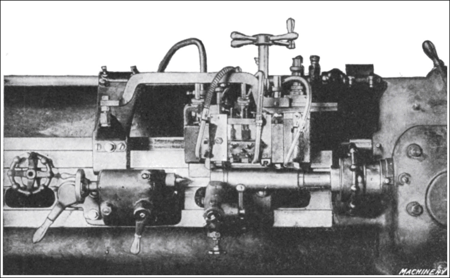
Fig. 36. Set-up for performing First Series of Operations on Russian Forged Shell on “Lo-swing” Lathe
To those familiar with the “Lo-swing” lathe, it will be appreciated that its chief efficiency lies in its system of multiple turning tools. Thus, on this job, tools H, I, J, K, L, and M are all mounted on one slide, and in the illustration are shown in the positions they occupy after taking their respective cuts. At the beginning of the cut, turning tools K, L, and M are drawn back clear of the work to allow sufficient clearance for tools H and I to operate. With the tools drawn back and the carriage at the extreme right of the bed, tool H is the first to come in contact with the work. This tool takes a roughing cut over the body of the forging, finishing at the radius on the nose.
Tool H is controlled in its action by a former pin on the tool-slide, held in contact with the face of cam former O by a stiff spring. Former slide O takes the place of the regular taper-turning former ordinarily used on the “Lo-swing” lathe. When the former pin in the slide carrying tool H reaches point P on former O, the tool is withdrawn to conform with the shape shown at N on the forging. The tool is then fed in further toward the axis of the arbor, until the former pin reaches point Q on the slide, when the radius on the nose is completed. Tool H is the only one mounted on a taper-turning block.
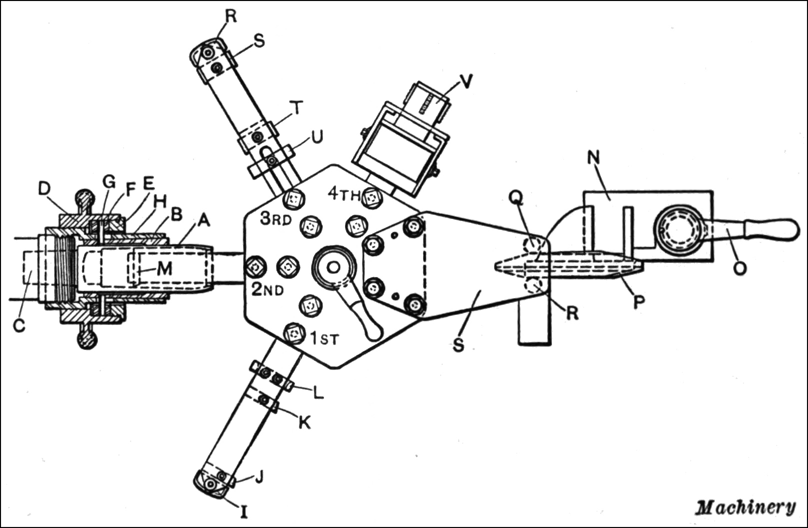
Fig. 37. Diagram showing Method of performing Second Series of Operations on Forged Shrapnel Shells on “Lo-swing” Lathe
Just after tool H passes point N, tool I commences to cut at the end of the forging, taking a finishing cut and ending up in the position in which it is shown in the illustration. After tool I reaches this position, the other tools J, K, L, and M are brought into action. Tools K, L, and M are so situated on the carriage that no lateral feeding is required. When these tools are in action, the roller support R takes the thrust. Tool K roughs out the band groove and is fed into the work by a handwheel. Tool L cuts the groove for attaching the brass case to the shell, and tool M, carried on the same block, faces the end. Tools K, L, M, and S are located on the same carriage and are fed in together. Tool S rounds the corner of the shell. The carriage on which tools K, L, M, and S are located is now drawn back out of the way, and the entire carriage moved over so that tool J can be used to under-cut the rifling band groove. After cutting off the center projection, the first series of operations on the shell is completed.
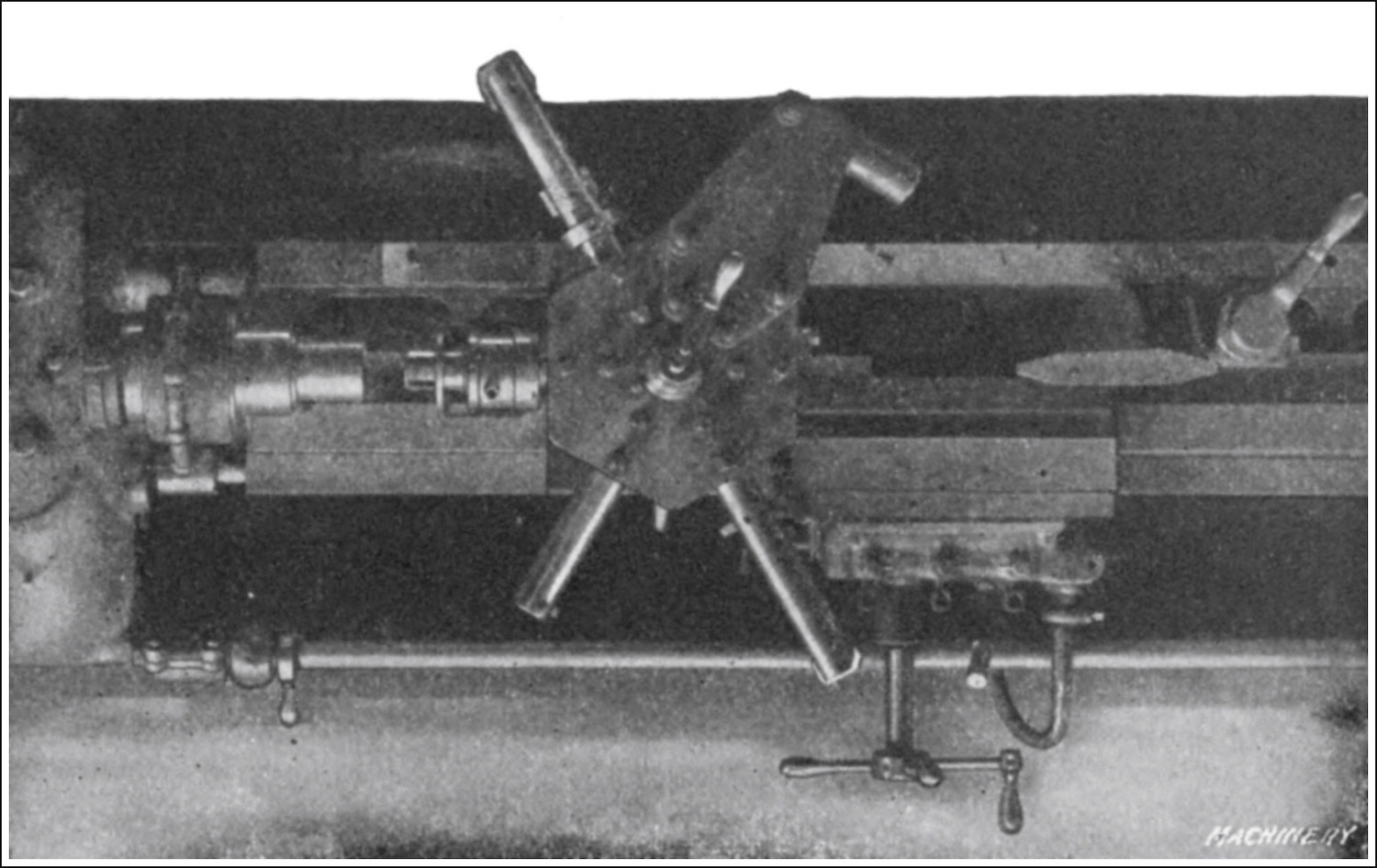
Fig. 38. Set-up on “Lo-swing” Lathe for performing Second Series of Operations on Russian Shell
Second Series of Operations on the Russian Shell.—The second series of operations is performed on the inside of the shell on the “Lo-swing” lathe, which is provided with a special turret for this purpose. As is shown in Figs. 37 and 38, the shell A is held in special collet jaws B that have a two-point bearing on the shell. Stop C in the spindle locates the shell in the chuck. To manipulate the chuck for tightening it on the work, handwheel D is turned, carrying with it the nut E and ring F. Ring F carries pins sliding in slots in sleeve H and driven into collet B, so that when nut E is drawn back it also carries collet B into the taper in sleeve H, closing the collet on the work. Turning handwheel D in the opposite direction releases the grip of the collet B on the work. The first operation is performed with tools I, J, K, and L. Tool I bores the powder pocket, tool J roughs the diaphragm seat, tool K rough-turns the thread diameter at the shell mouth, and tool L faces the end. The turret is now indexed, and boring-bar carrying tool M is brought into operation. This tool turns the curved interior of the shell. To accomplish this, the turret locking-pin is removed, allowing the turret to float on its central axis. Fastened on the ways of the lathe at the rear of the turret by a clamp O is the cam bracket N carrying the guiding cam P. This cam, through pins Q and R in bracket S, controls the float of the turret and guides the cutting tool M. In the illustration, the tool is shown at the end of the cut. It will also be noted that one surface of the cam is curved and the other is straight; therefore, to compensate for this and also to steady the turret, pin R is backed up by a spring. Clamp O is now released and bracket N moved back to allow the turret to be indexed. Bracket N is located, when brought into the operating position, by a stop on the bed of the lathe.
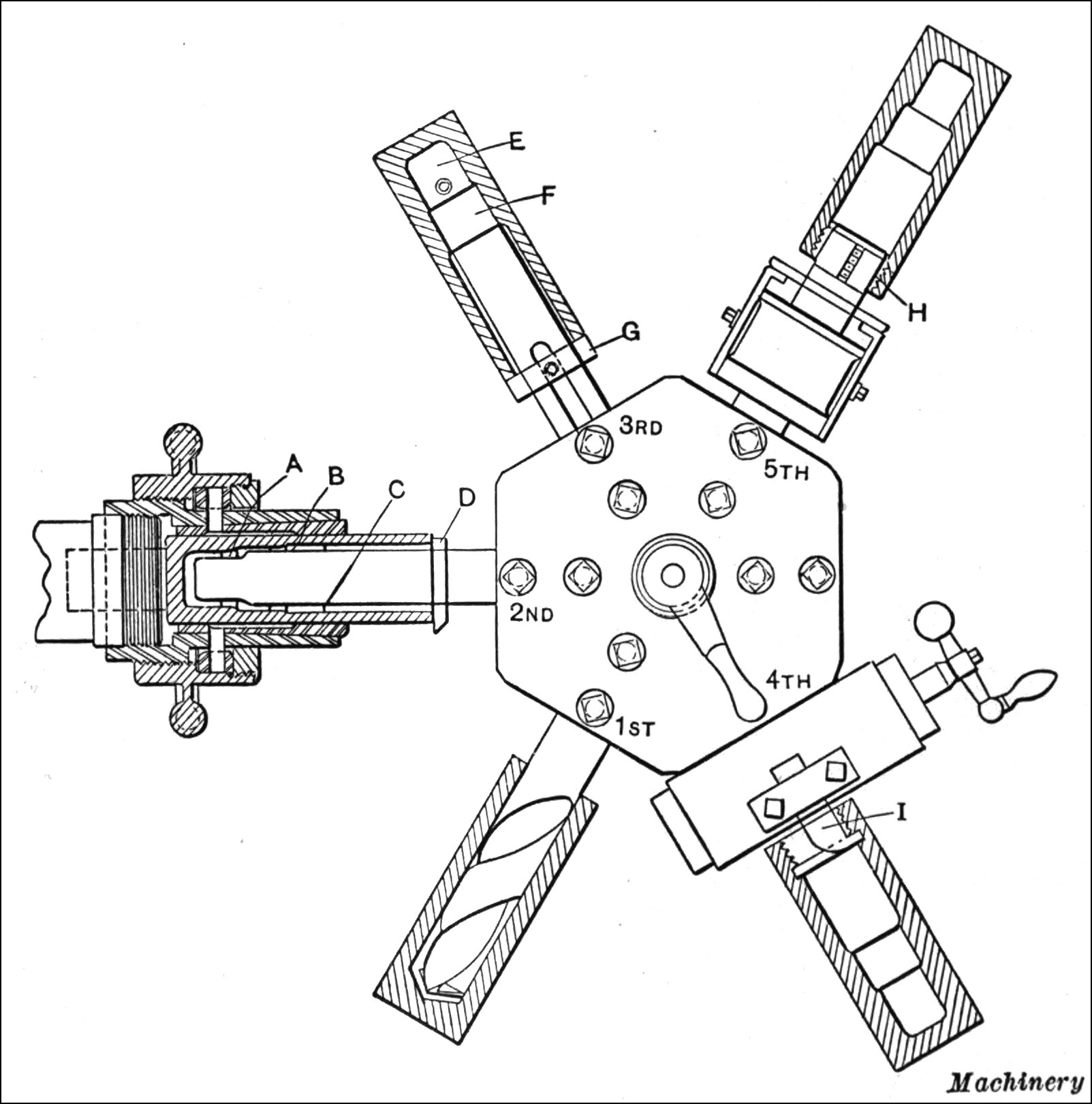
Fig. 39. Diagram showing Method of machining French Shells on “Lo-swing” Lathe—First Series of Operations
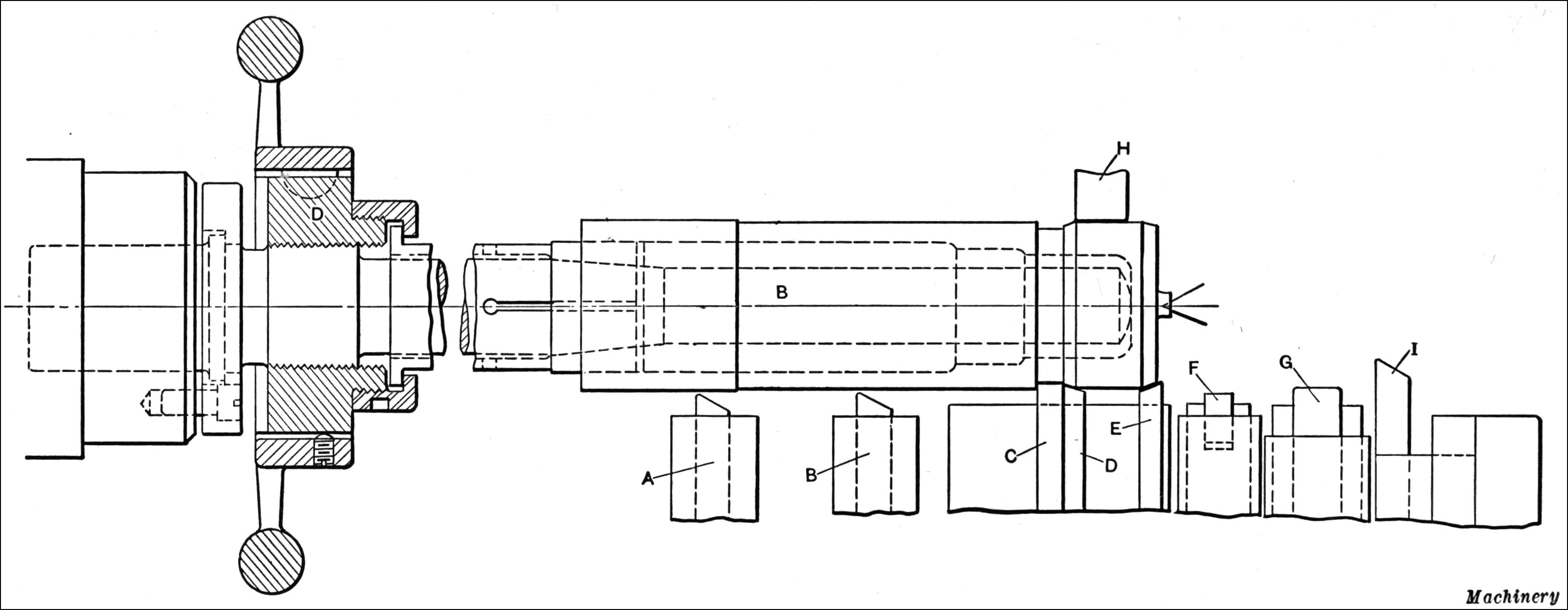
Fig. 40. Diagram showing Method of holding and applying Tools on “Lo-swing” Lathe for performing Second Series of Operations on French Shell
In the third position, tool R finishes the powder pocket, S the diaphragm seat, and T the thread diameter, whereas U acts as an adjustable stop for the depth of the various tools. The fourth and last operation is tapping with a collapsible tap V. This completes the machining of the Russian shell on the “Lo-swing” lathe.
Machining French Shrapnel Shell on “Lo-swing” Lathe.—The machining of the French shrapnel shell is well suited to the “Lo-swing” lathe. A great many of the French shells are made from solid bar stock, and when this is the case, the first operation, performed as shown in Fig. 39, consists in rough-drilling. If the shell is made from a forging, this operation, of course, is dispensed with and the first tool used carries boring and facing cutters, as shown at A, B, C, and D. These rough-bore the three diameters on the inside of the shell and face off the end to length. The next operation is accomplished with two finishing boring tools E and F, the depth of which is obtained by an adjustable collar G that comes against the produced with a collapsible tap H. The turret is then indexed two holes, bringing the special recessing tool into position. This tool is of the cross-slide type and carries a back recessing cutter I. This completes the first series of operations on the shell.
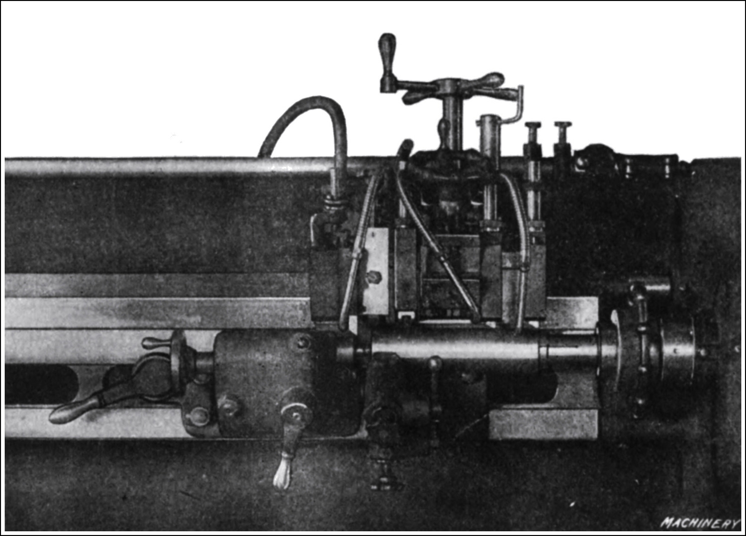
Fig. 41. Set-up on “Lo-swing” Lathe for performing Second Series of Operations on Straight Type of French Shell
Second Series of Operations on Shell. French—The second series of operations on a French shell is accomplished as shown in Fig. 40. Here the shell is held in the same manner as described in connection with Fig. 35. The forging is placed on arbor B that has an expanding sleeve C operated by the hand-clamping wheel nut D. Eight cutting tools are located on the carriage. Tool A turns the diameter at the open end of the shell, B the central part, C cuts the band groove, D chamfers the section adjacent to the band groove, E chamfers the end of the shell, and F knurls the band groove. Roll G, in connection with roll H, supports the shell while the knurling is being done, whereas tool I faces off the end of the shell. At the beginning of the cuts, tools C, D, E, and knurl F, also roll G and tool I, are withdrawn. This permits tool A to cut the front end of the shell at the beginning and finish the diameter at the open end of the shell. Tool B next comes into action and turns the central part of the shell. Tool C is then located in the correct position for the band groove and the carriage on which tools C, D, and E are located is fed straight in, cutting the band groove and chamfering. Knurl F is then brought into position to knurl the groove, with roll G backing up the work against roll H. The last operation is to cut off the center projection with tool I.
Fig. 41 shows the tool set-up on the “Lo-swing” lathe for machining the straight type of French shell, in which two tool-blocks are used for doing the straight turning. The leading tool turns the end of the shell a little larger than the main body. The procedure for grooving, knurling, and facing the shell is that previously described for the forged shell, which is shown in Fig. 35. On the French shrapnel shell the second operation follows directly after the first, whereas on the Russian forged shell a nosing-in operation comes between the two machining operations.
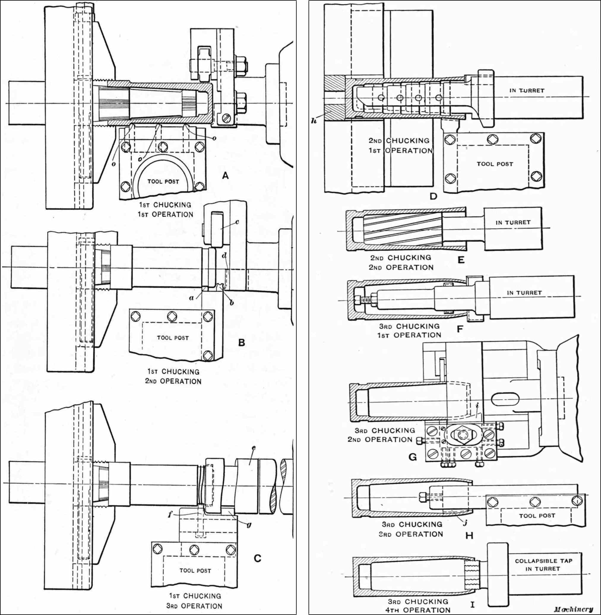
Figs. 42 and 43. Set-up and Tool Equipment on the “Libby” Turret Lathe
Using the “Libby” Turret Lathe for Machining Shrapnel Shells.—One of the many ways of machining a shrapnel shell is illustrated in Figs. 42 and 43. This shows the set-up on the “Libby” turret lathe, manufactured by the International Machine Tool Co., Indianapolis, Ind. In the first chucking, the forging, as shown at A, is held on a special solid arbor provided with a series of corrugations where it contacts with the forging. This, in addition to providing a rigid support, assists in gripping, and the shell is also gripped by a pair of chuck jaws that act as drivers. First, a gang tool-holder carrying three stellite turning tools o is brought into position, and the cutting is started, continuing for a distance of one-third of the length turned. To provide additional support, a roller back-rest, carrying a facing tool, is brought in to steady the work, and, as it is fed forward, the end of the forging is faced off and chamfered.
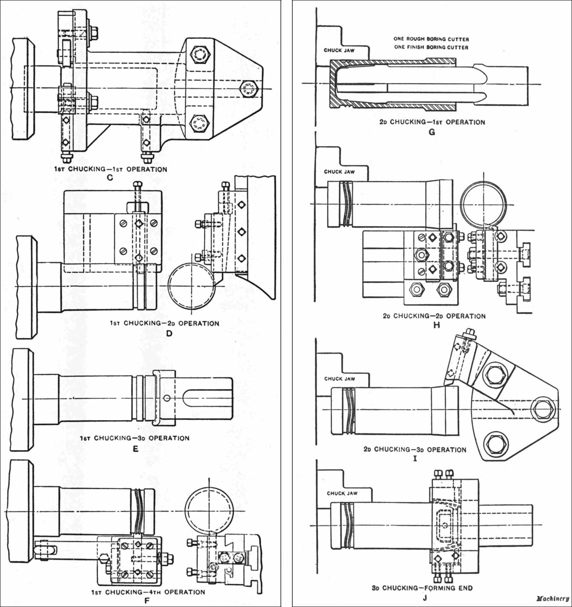
Figs. 44. and 45. Machining Shrapnel Shell Forgings on a 22-inch Extra-heavy Turret Lathe
The second operation on the first chucking is shown at B. Here the cutter a is brought in first and starts the band groove, after which the under-cutting tool b is brought in to under-cut the edges of the groove. In the meantime, roller c supports the work. Upon the completion of the groove, the holder carrying cutter d is advanced to finish-face the end of the work and chamfer.
The third operation—cutting the waves in the band groove—is of an interesting character and is accomplished as shown at C. A cam e which is free to rotate with the work is first brought in contact with it; then the cross-slide is advanced, carrying the waving tool f and the guide g. The guide g fits in the cam groove and controls the operation of the waving tool.
In the second chucking on the first operation the shell is reversed in the chuck and is held in the manner indicated at D, Fig. 43. The forging is located in the chuck by a stop-collar h, and is gripped on the external diameter by the jaws of the chuck. A stepped boring tool carrying five inserted blades is brought in to rough-bore the internal diameters and machine the shell to the proper thickness at the bottom of the powder pocket. This tool also carries a facing cutter that faces off the shell to the proper length. While the boring tool is working, a broad turning tool, held on the cross-slide, is brought in to bevel the nose preparatory to closing-in. The next step is to taper-ream the internal diameter, as shown at E. This completes the operations for the second chucking.
The nose of the shell is now heated and closed in, after which the third series of operations is performed. The first step in the third chucking is to bore for the thread and face the end of the shell with a turret tool, as shown at F. The next operation is to machine the curved contour of the nose of the shell with a special turret tool as shown at G. Here a wide forming cutter i, held in a turret tool-holder, is brought in contact with the work, finishing the nose of the shell to the proper form. During this operation, the shell is supported by a roller in the holder.
The next operation is to form the inside of the nose of the shell to the proper shape, as shown at H. This is accomplished with a forming blade j, held in a holder clamped in the toolpost. Following this, a collapsible tap is brought in from the turret to thread the nose of the shell, as shown at I.
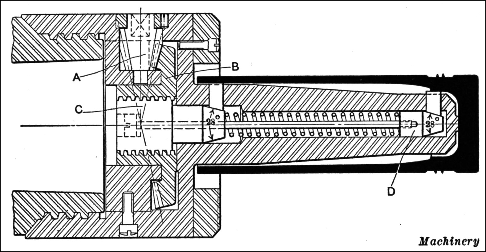
Fig. 46. Method of holding Shrapnel Shells for First Operation on a 22-inch Turret Lathe
Machining Shrapnel Shells on a Heavy 22-inch Turret Lathe.—Still another method of machining shrapnel shells in a heavy turret lathe is shown in Figs. 44 and 45. The shell being machined is an 18-pound British shrapnel shell made from a forging. It is held on an expanding arbor for the first operation, as shown in Fig. 46. The arbor is of the three-point support type and is positive in its grip. Around the periphery of the nose-piece are located three pinions A capable of being rotated by a square-ended wrench. These mesh with teeth in bevel gear B which, in turn, is threaded onto arbor C. The forward end of this arbor is cone-shaped and operates the three gripping fingers in the open end of the shell, whereas another rod passing through arbor C and connected to plunger D operates, through the coil spring, the three fingers used in gripping the shell by the powder pocket. This arbor holds the shell securely while the machining operations are being accomplished.
The first operation performed at the first chucking of the work is shown at C in Fig. 44. Here a turning tool-holder clamped to the turret and carrying two cutters is advanced and takes a roughing cut from the exterior diameter of the shell for practically its entire length. The shell is supported by three roller supports as illustrated. The second operation at the first chucking is performed from the cross-slide, as shown at D. Here a forming tool of the tangent type roughs out the rifling band groove, leaving sufficient metal in the center for the production of the wave ribs. The third operation is facing off the closed end of the shell from the turret as shown at E, and the fourth operation consists in machining the waved ribs as shown at F. The tool for accomplishing this operation is held on the cross-slide and is operated from a face-cam on the nose of the spindle.
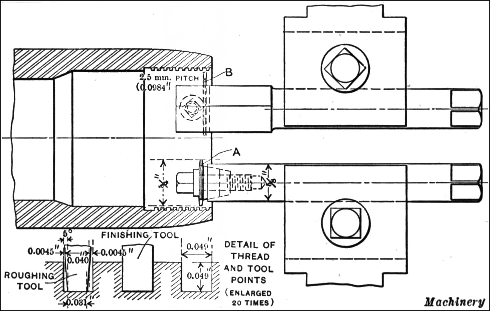
Fig. 47. Cutting Square Thread in Nose of French Shrapnel Shell In “Automatic” Threading Lathe
In the second chucking the shell is held in a three-jaw scroll chuck. The first operation is to rough-bore the inside of the shell and powder pocket with a tool G, Fig. 45, held in the turret; directly after this a finishing tool of the same shape is brought in, finishing the surfaces previously roughed out. The second operation is to face off the open end of the shell and taper-form back of the nose from the cross-slide, as shown at H, and at the same time turn that portion of the exterior surface of the shell not machined in the previous operation with a tool clamped to the turret as shown at I.
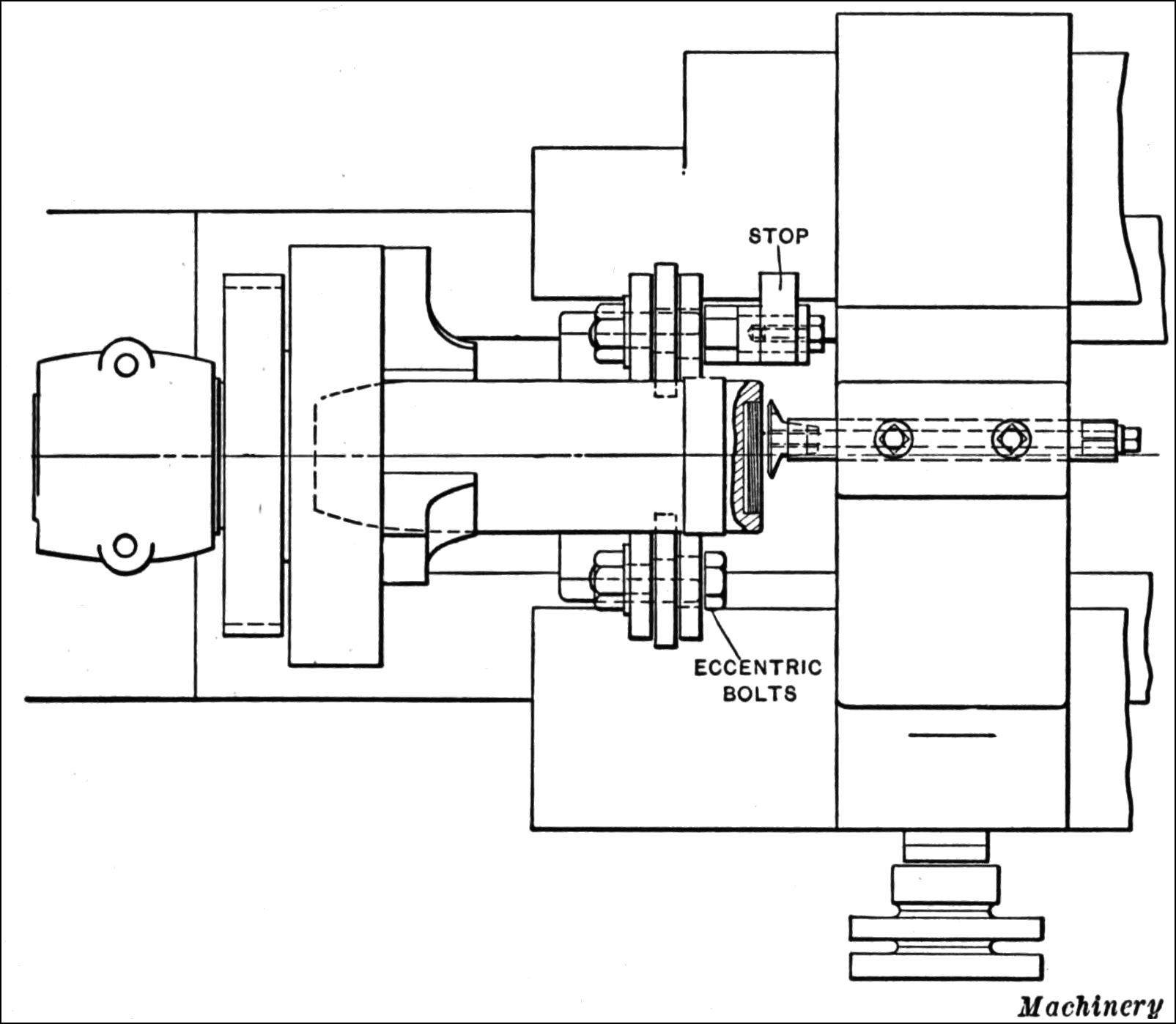
Fig. 48. Threading Base End of Bar-stock Shrapnel Shells in “Automatic” Threading Lathe
Previous to the third chucking, the nose of the shell is heated and closed in. The shell is then held in a three-jaw scroll chuck provided with special jaws. The first operation, as shown at J, consists in boring and turning the nose of the shell with a tool held in the turret. Following this, the hole is reamed with a standard reamer and tapped with a collapsible tap. Both of these tools are held in the turret, but are not shown in the illustration. This completes the machining operations on the shell.
Threading Shrapnel Shells on “Automatic” Threading Lathes.—Considerable difficulty has been experienced in cutting the square thread in the nose of the French shrapnel shell. One method which accomplishes this operation satisfactorily is shown in Fig. 47, and is accomplished on a 12-inch “Automatic” threading lathe built by the Automatic Machine Co., Bridgeport, Conn., and equipped with special tools for this purpose. Referring to this illustration, it will be seen that two tools are used—a roughing tool A, and a finishing tool B. Tool A roughs out the thread to a shape similar to the Acme type of thread, whereas tool B squares it up. The roughing and finishing tools are held on the forward and rear carriages, respectively, and are operated simultaneously, being advanced throughout the length of the thread, withdrawn and returned to start a new cut. The method of operating the tools is one of the chief features of the “Automatic” threading lathe.
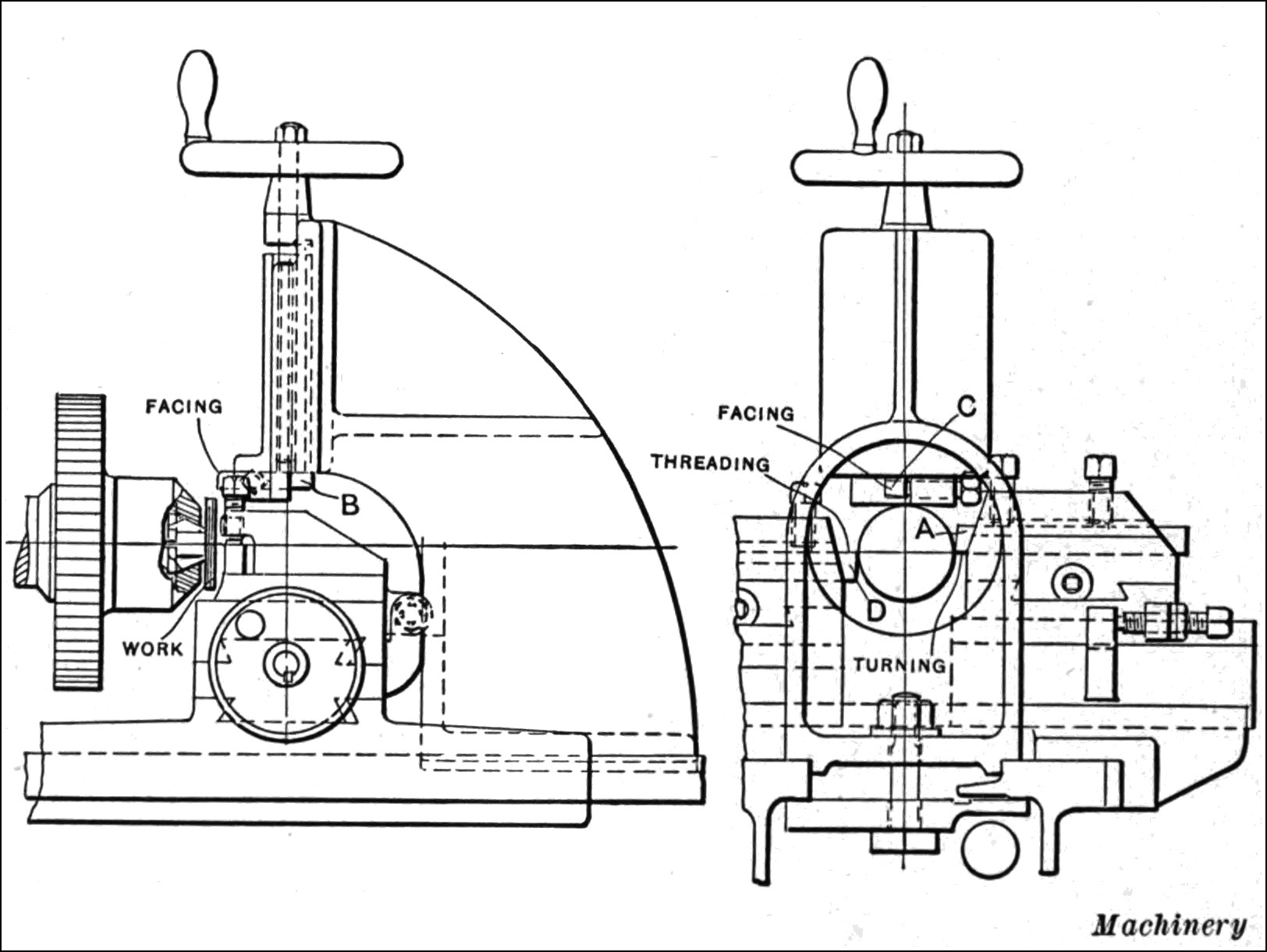
Fig. 49. Turning, facing, and threading Plugs for Closed End of Bar-stock Shrapnel Shells in “Automatic” Threading Lathe
The base end of shrapnel shells when made from bar stock is as a rule bored out and a plug inserted to eliminate any piping effect in the bar. Fig. 48 shows the method of accomplishing this operation on a 12-inch “Automatic” threading lathe. The work is held in a three-jaw universal chuck and is supported by a roll steadyrest comprising two rolls that are located beneath the work. On the extended end of the rear roller stud is fastened a swinging stop that is used for locating the base of the shell in the correct position ready for threading. The base of the shell is counterbored in another machine, previous to the threading operation. The threading is done with a circular tool held on a special internal threading tool-holder, the latter being retained in the toolpost carriage. The threading tool-holder can be moved longitudinally to bring it into the proper relation to the work. It is also held so that the cutting edge is turned upside down as this action forces the work down in contact with the roller supports. By handling the work in this manner, a steadyrest of the ordinary type is dispensed with and the operation of the attachment facilitated.
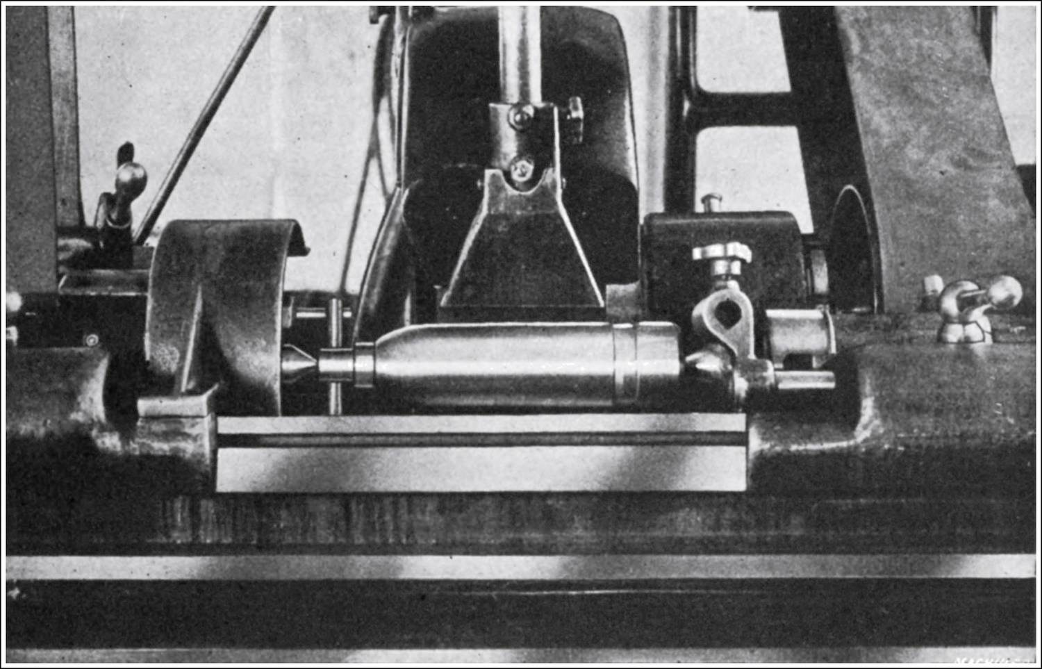
Fig. 50. Grinding Shrapnel Shells on a Norton Special-purpose Grinding Machine
One method of making plugs for the base end of shrapnel shells when made from bar stock is shown in Fig. 49. For this work, a 12 by 4 “Automatic” threading lathe equipped with special tools designed for this purpose is used. The machine is provided with a draw-in collet chuck that holds the rough-forged blank. The order of handling the operations on this machine is to use the rear tool A for turning the external diameter of the plug. This is handled at the same rate of feed as that required for threading, so that it is sometimes necessary to take more than one cut, depending on the amount of material left on the diameter. The vertical slide B is for facing only and carries a cutting tool C. This is supposed to finish the face in one cut, but as the work will spring considerably, a light finishing cut is taken when the tool is being drawn back from the center to the circumference of the work. The threading tool D is held on the front toolpost and is of single-point construction. The feed given to this tool is automatically controlled, both as to pitch and depth of cut at each traverse.
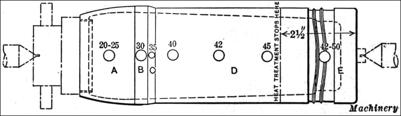
Fig. 51. Diagram showing Scleroscope Hardness Test of Heat-treated Shrapnel Shell at Various Points along its Surface
In actual operation, both the threading and turning tools are in motion all the time on the work, but the tools are independently controlled so that either one can be operated separately. A stop is provided on the back toolpost so as to turn each plug to the same diameter. The automatic throw-out for the feed of the threading tool is set from the front handle on the ratchet and pawl as regularly furnished on the “Automatic” threading lathes.
Grinding Shrapnel Shells.—An increasingly large number of shrapnel shell manufacturers are finishing the steel shell by grinding instead of finish-turning. That is, the exterior surface of the shell is rough-turned to within from 0.030 to 0.080 inch of the finished size and is then finished to the required limits and shape by grinding, as shown in Fig. 50. It is claimed by the advocates of grinding that the finishing operations are more speedily performed in this manner and that a more accurate and concentric shell is produced. They also point out the fact that portions of the shell are so hard that it is extremely difficult, if not impossible, to turn it in the allowable time.
The varied heat-treatment given to the shell on the closed end and nose leaves it harder in some sections than others, as indicated in Fig. 51. The section E, 2¹⁄₂ inches from the closed end of the shell, must strike from 42 to 50 on the scleroscope, and the section A at the nose must strike between 20 and 25. The section marked D, or that part of it to the left of the line that marks the limit of the heat-treating on the closed end, has not been heat-treated at all, and partly on this account, and also because of the gradually diminishing thickness of the shell along this section, it strikes between 40 and 45, decreasing as the thickness of the wall diminishes, until at C the section strikes but 35. Section B, adjacent to the annealed nose of the shell, strikes about 30 on the scleroscope.
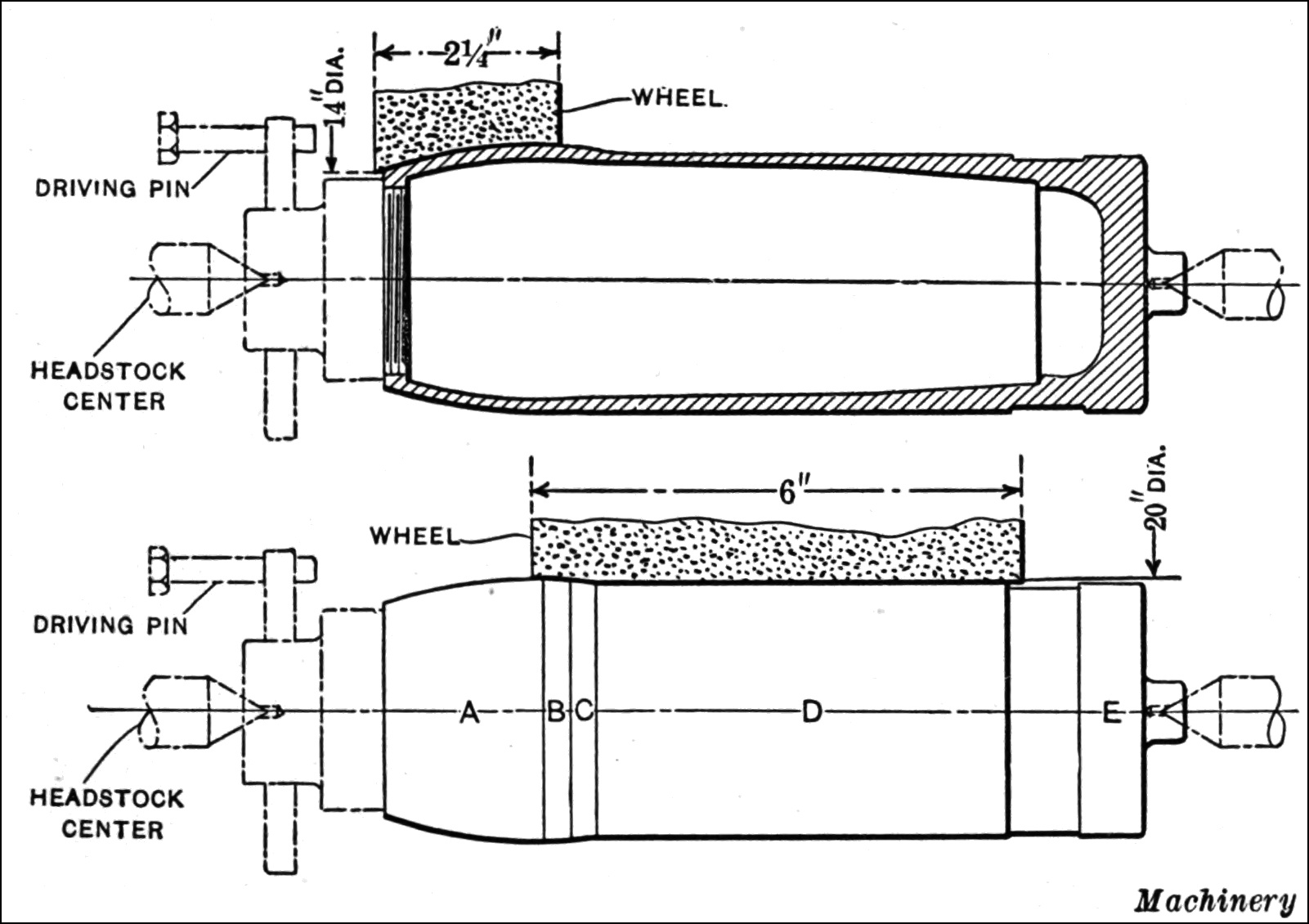
Fig. 52. Two-operation Method of grinding Shrapnel Shells on Norton Grinding Machines
On the other hand, some manufacturers are not putting the shell through this heat-treating and tempering process, and omit the annealing and machining of the nose after the nosing-in operation. This leaves the nose with considerable stock to remove and in such a condition as regards hardness that the grinding machine becomes a necessity. In the face of these varying degrees of hardness of the shrapnel shell, it will be seen that it is difficult to secure wheels of the right grain and grade to suit all of these conditions. With this information in mind, we can more intelligently take up the actual grinding of the shell. The Norton Grinding Co., Worcester, Mass., has been actively engaged in developing methods of grinding shrapnel shells and the following illustrations and descriptions apply to this work.
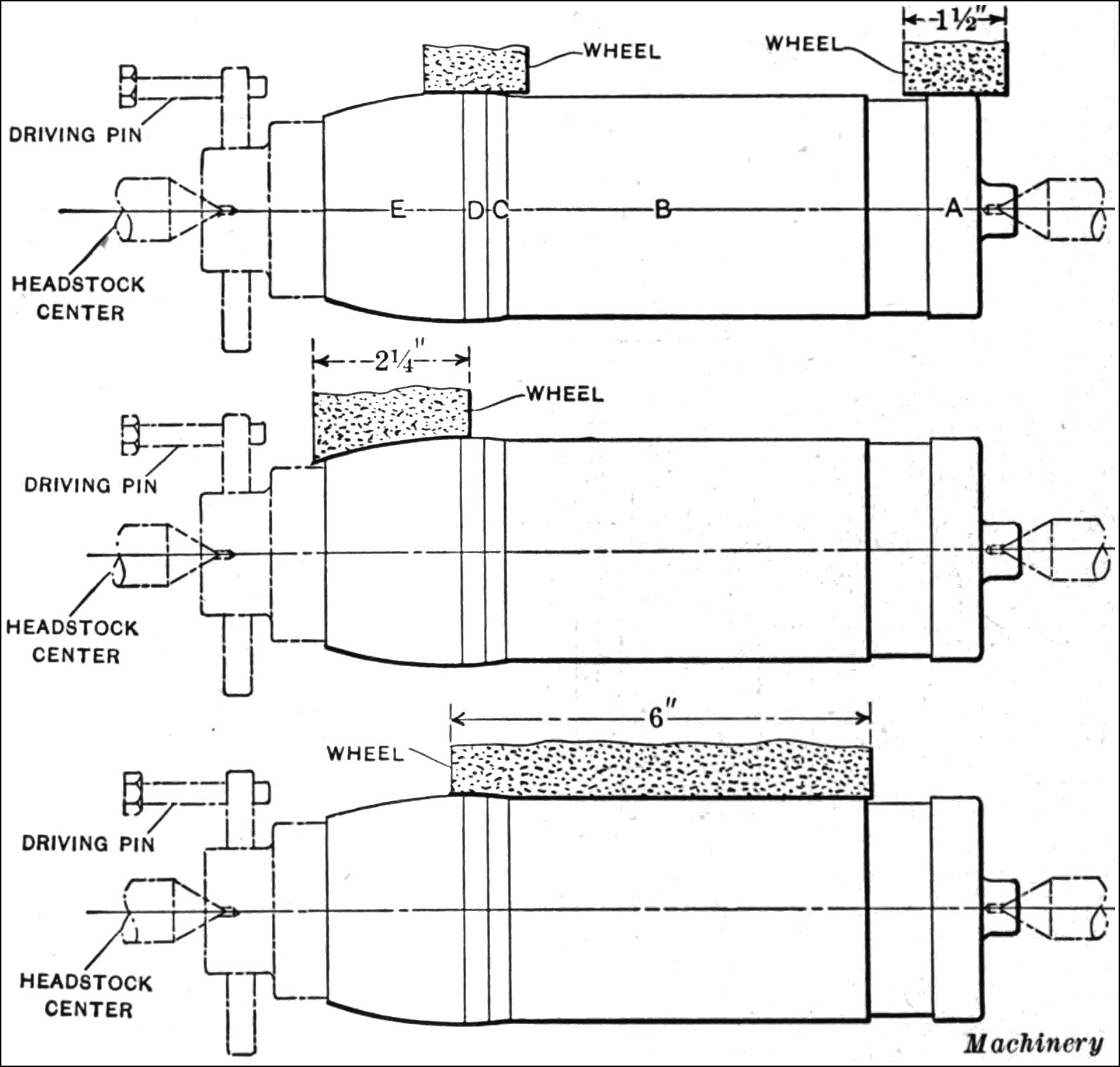
Fig. 53. Three-operation Method of grinding Shrapnel Shells on Norton Grinding Machines
Fig. 52 shows the two-operation method of grinding the shrapnel shell. Section A at the open end of the shell is covered by a wide-faced wheel formed to shape, that finishes the radius on the nose at one in-feeding of the wheel. Sections B, C, and D are covered by a wide-faced wheel, formed to shape so as to finish these three surfaces at one in-feeding of the wheel. Section E at the closed end of the shell is finished completely by turning.
Some manufacturers use a three-operation method of grinding the shrapnel shell as illustrated in Fig. 53. In this case, the sections A and D are first ground with the same wheel, as American manufacturers deem it advisable to grind surface A rather than to finish it by turning. The second stage in this grinding is the finishing of the nose E with a formed wheel, and the third stage is the finish-grinding of the body at points B and C.
Two-operation Method of Grinding Shrapnel Shells.—The procedure followed in grinding shrapnel shells by the two-operation method is first to screw plugs into the open end of the shells, as shown in Fig. 52. The outer ends of these plugs are centered, and the projection left on the closed end of the shell with the center intact acts as a means of supporting the shell. Some of the Canadian manufacturers vary this practice by cutting off the center projection on the closed end of the shell and fitting a cap with a center hole over the closed end. Others use a ball-bearing cup center to carry the closed end. American manufacturers, however, leave the center projection on the shell until after the grinding has been finished.
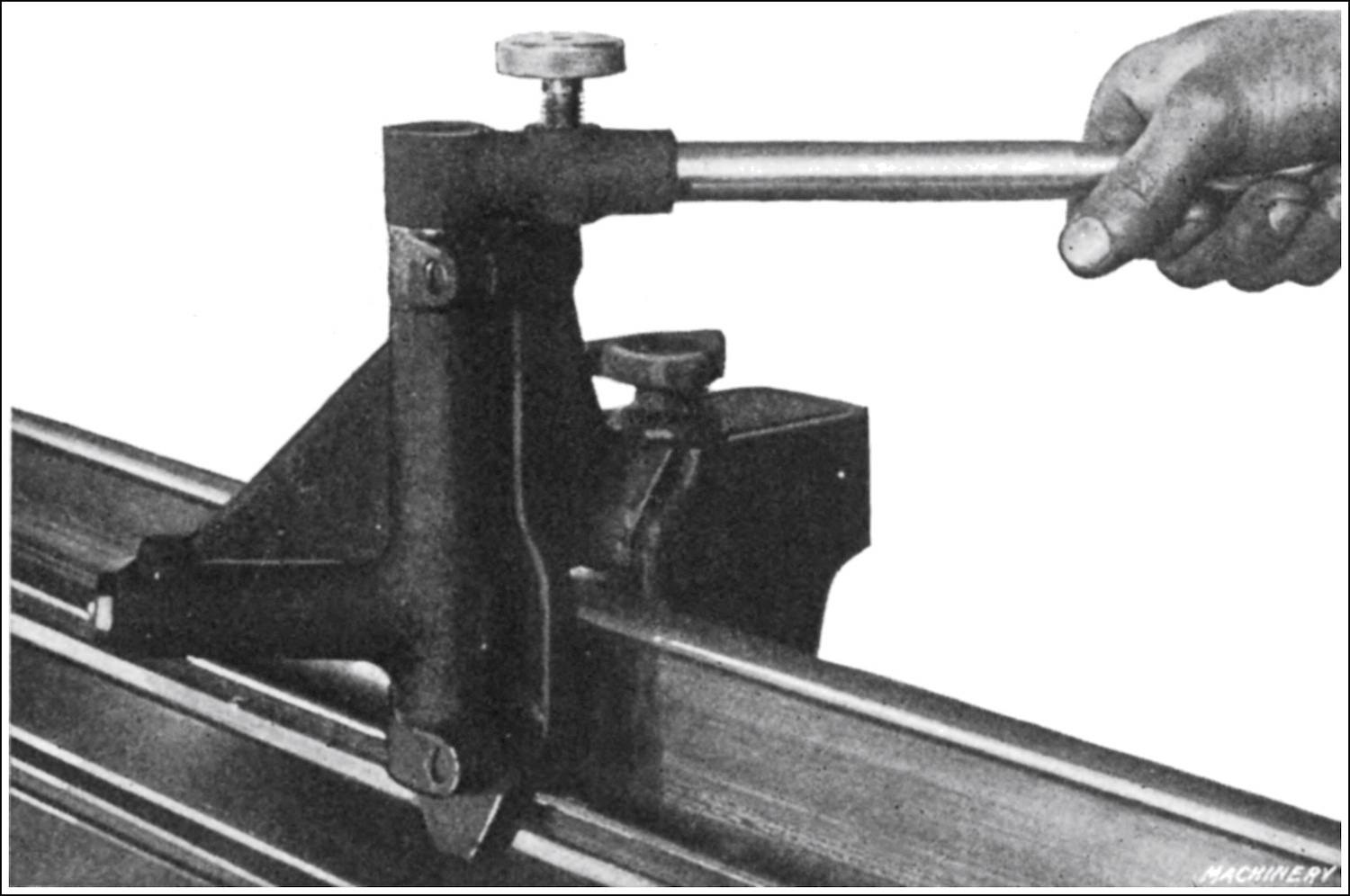
Fig. 54. Radius Wheel-truing Device for forming Grinding Wheel for grinding Shrapnel Shell Nose
In grinding the nose end of the shell, the amount of metal removed varies from 0.020 to 0.090 inch on the diameter. The grinding wheel operates at from 6000 to 6250 surface feet per minute. The speed of the work is 75 revolutions per minute, or a surface speed of practically 75 feet, and the machine used is a Norton 6 by 32 plain grinder. The wheel used is generally 14 inches in diameter by 2¹⁄₄-inch face. The wheel requires truing for every five to twenty shells, depending upon the amount of metal removed and the hardness of the shell. For truing, a simple radius fixture carrying a diamond is used. Fig. 54 shows this wheel-truing device clamped on the grinding machine bed. It is applied in the same manner as the usual steadyrests used for supporting the work. The diamond is mounted in a swinging arm that is operated by a hand lever as shown. By successive cuts across the wheel, the desired shape is attained.
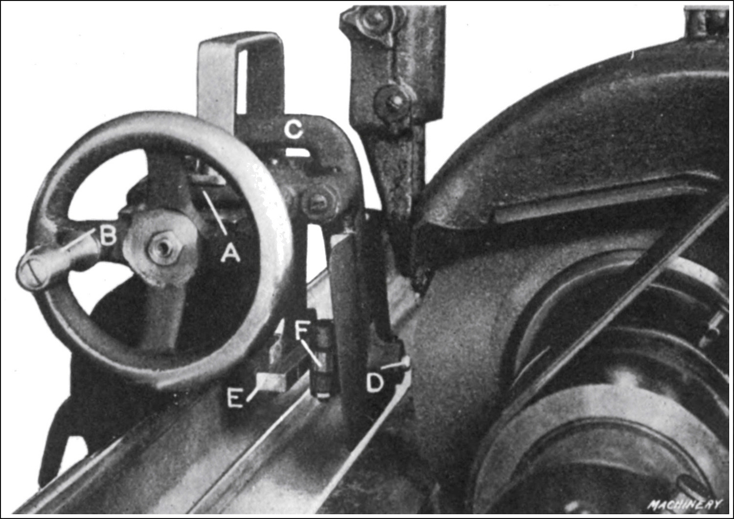
Fig. 55. Norton Special Form Wheel-truing Device for truing Wheel for grinding Shrapnel Shell Body
For grinding the body either a 10 by 24 special-purpose or 10 by 36 Norton grinding machine is employed. The amount of metal removed from the body varies from 0.030 to 0.075 inch on the diameter, and the limits vary from 0.002 to 0.010 inch, depending largely on the requirements of the plant in which the work is being done. The wheel used on the body is 20 inches in diameter and is of the ring-wheel type. It will be noticed in Fig. 52 that the wheel for grinding the body is also formed to shape. The method of truing the wheel for shaping the shrapnel shell body is shown in Fig. 55. This attachment is clamped to the front of the grinding machine bed and at the top of the bracket is fitted a slide A operated by handwheel B. Upon the face of this slide nearest the grinding wheel is pivoted an angular arm C that supports the diamond D at its lower end. Under the end of the upper arm is a spiral spring that keeps the diamond normally back from the wheel. A plate former E clamped to the bottom face of the bracket is shaped to agree with the form to be given the wheel. At the lower extremity of the arm and behind the diamond is mounted a roll F that bears constantly against form E. When the diamond slide is reciprocated by turning the handwheel, the diamond is made to traverse a path conforming with the cam that guides it. By moving the wheel in toward the diamond and making successive traversings of the diamond, the wheel is given the desired shape.
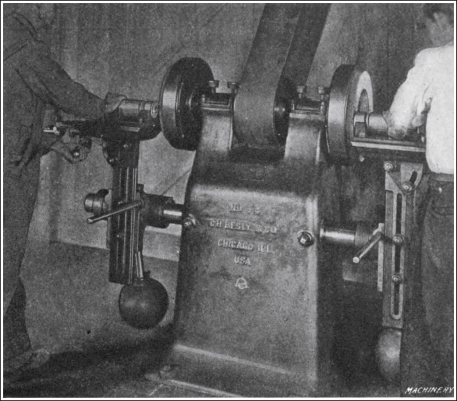
Fig. 56. Besly No. 14 Ring Wheel Grinder equipped for grinding Shrapnel, but shown without Hoods and Water Attachments
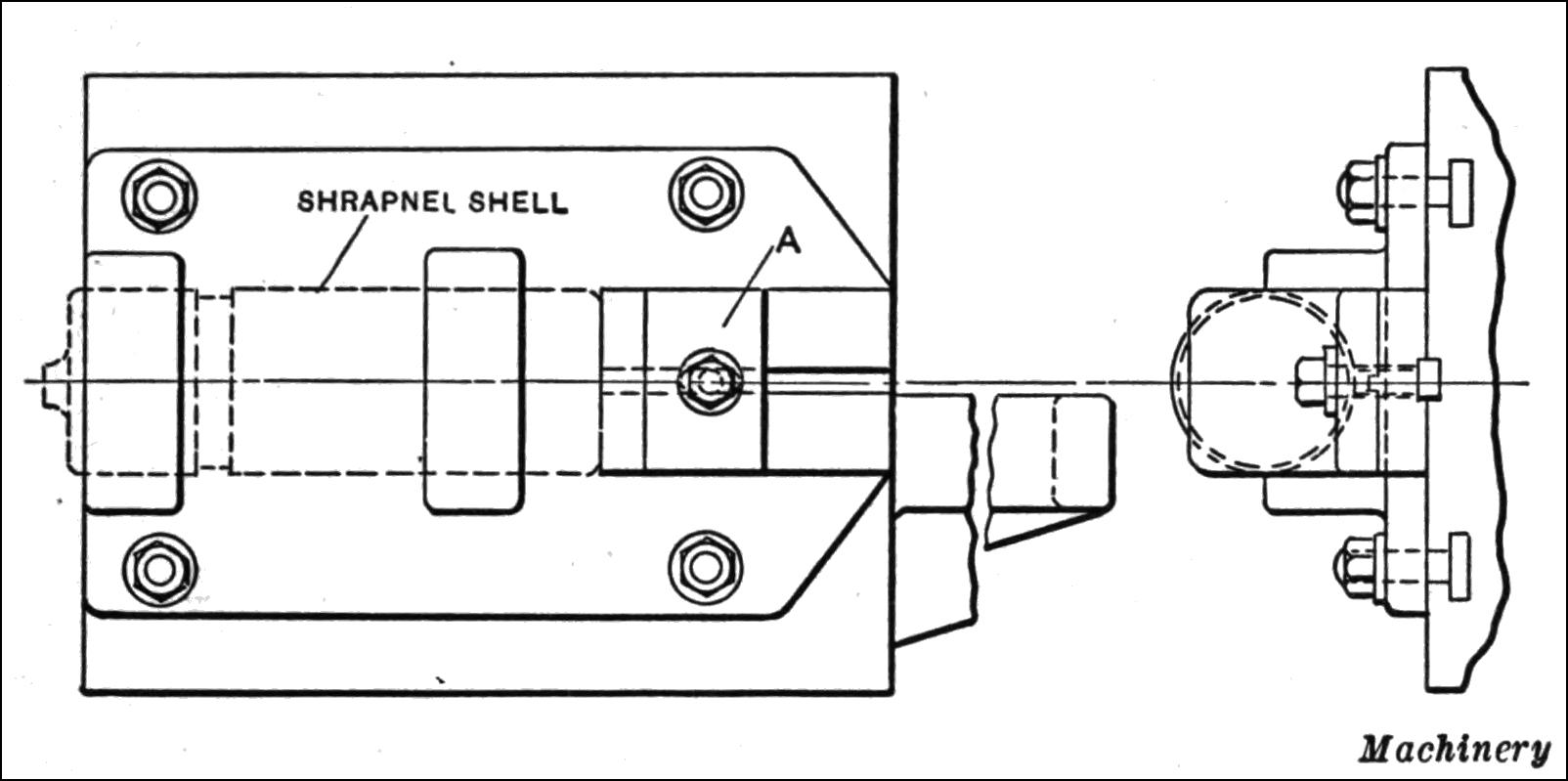
Fig. 57. Fixture used on Besly No. 14 Ring Wheel Grinder for grinding Center End from Shrapnel Forgings
For grinding the body, the wheel must be trued after every ten to twenty-five shells are ground, depending upon the amount of metal removed and the hardness of the shell. In grinding shrapnel shells, the usual method is to fit a lot of the shells with the driving plugs and carry them all through to completion before removing the plugs.
Removing Center End From Shrapnel Forgings.—For performing practically all the machining operations on the shell, a center projection is left on the closed end of the shell for supporting it. This, of course, must be removed before the shell is completed. One method of doing this is to use a Besly No. 14 ring-wheel grinder equipped with a special fixture. A Besly grinder fitted up for this work is shown in Fig. 56, and the fixture used for holding the shell is shown in Fig. 57. The machine, as furnished, is arranged for wet grinding, but is not so fitted up in the illustration. The fixture is fastened to the geared lever feed table and is of simple design. It is provided with a backing-up stop A, the work resting in two semi-spherical groove projections on the fixture. The operator simply holds the shrapnel shell in place by hand and then feeds it in against the wheel and traverses it past in the usual manner. The time for removing a ⁵⁄₈-inch diameter stub end projecting ³⁄₈ inch from the body of the shell is less than a minute.
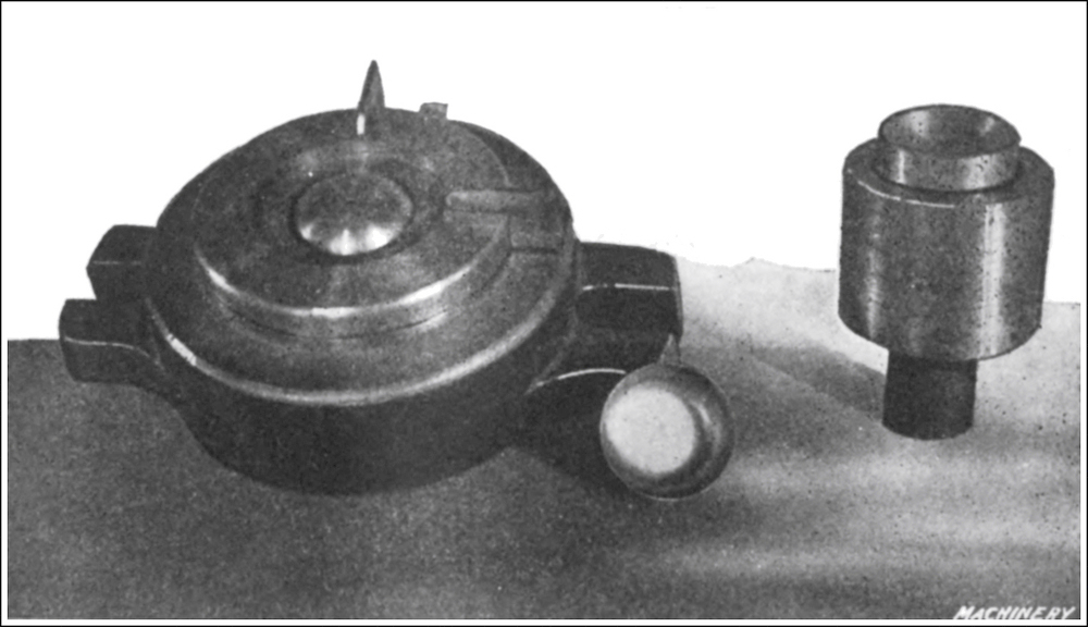
Fig. 58. Tools for making Base of Powder Cup
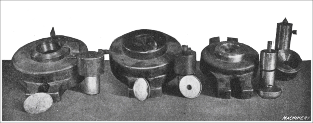
Fig. 59. Tools for making Top Member of Powder Cup
Press Tools for Making Powder Cup.—In the British shrapnel shell, the powder in the base of the shell used for exploding it and ejecting the lead bullets, etc., is held in a tin-plate powder cup. This is completed in the punch press in the manner shown in Figs. 58 and 59, and comprises two parts, a base and a top. The base is made from tin plate 0.022 inch thick, whereas the top is made from 0.036 inch thick tin plate. The bottom of the cup is completed in one operation with the punch and die shown in Fig. 58, which is held in a single-action press. It is turned out from a blank 3⁷⁄₃₂ inches in diameter and is cut out and formed in one operation. The completed size is 2¹⁄₄ inches diameter by ⁷⁄₈ inch high. After cupping, the top edge is trimmed in a turret lathe. The press operations on the top, as shown in Fig. 59, are a little more complex. The first operation consists in cutting out a blank 2¹⁹⁄₃₂ inches in diameter. Then the edge is turned up with another punch and die shown in the center of the illustration. The next operation is piercing the center with the punch and die at the right, and the last operation is drawing out a flange around the pierced hole. The tools for this operation are shown to the extreme right, as is also a completed powder cup. The final operation on the cup consists in soldering the top to the base.
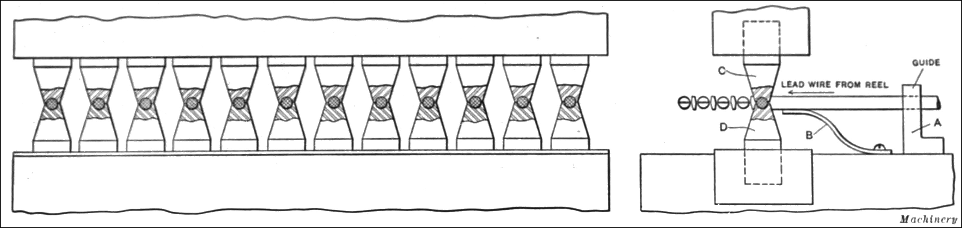
Fig. 60. Diagram illustrating “Twelve-punch” Method of making Shrapnel Bullets from Lead Wire
Shrapnel Bullets.—The most deadly and effective parts of a shrapnel are the lead bullets which are held in the shell. When the timing fuse explodes the powder in the base of the shell, the nose is blown off and the bullets are thrown out in a cone shape. The range covered by these bullets in the 18-pound shrapnel shell is about 250 square yards. The lead bullets, which in most shrapnel are ¹⁄₂ inch in diameter, are made from several different compositions, but consist chiefly of 87¹⁄₂ parts lead and 12¹⁄₂ parts antimony. The number of bullets carried in shrapnel shells of the different governments varies. There are 252 in the American 15-pound shell, and 235 or 236 in the British 15-pound shell. The bullets used by the U. S. government have six flattened sides, to facilitate packing, whereas those used by foreign governments are spherical.
There are several methods of making shrapnel bullets. One is to cast the bullets in iron molds, which are split in the center, so that the bullet can be removed when cast. Another is to cut off slugs from lead wire and strike these between dies in a heading machine. The bullet heading machine takes the wire from a reel, cuts it off, forms it and trims off the resultant flash automatically. In making the American bullets, a second operation follows, consisting in flattening the sides. The Waterbury Farrel Foundry & Machine Co. furnishes unit equipments for doing this work. For the flattened bullets, the unit consists of one hydraulic wire extruding press and fourteen heading machines capable of giving a production of 850 bullets per minute. For the spherical bullet, the unit equipment consists of one hydraulic extruding press and eight heading machines, giving a production of 950 bullets per minute.
The method of casting lead bullets in ordinary molds is antiquated, and another method somewhat similar to that just described has taken its place. The first step is to produce the wire from which the bullets are eventually made. This is accomplished in two ways. The first is the hot metal process and consists in pouring the molten lead into a cylinder, from which it is extruded through a die by a plunger advanced into the cylinder. By this method, it is necessary to allow the metal to settle before the press can operate. An improvement over this is utilized in presses built by a hydraulic lead press manufacturer of Brooklyn, and consists in first casting ingots of the required diameter and length and then charging the press with these instead of pouring the molten lead into the press chamber. Two presses have been designed for this process. One has a capacity of 700 tons and is charged with ingots weighing 150 pounds, whereas the other has a 900-ton capacity and is charged with 200-pound ingots. The product from these two machines is 1800 pounds of lead wire from the small and 2500 pounds from the large press per hour. The wire as it is extruded from the die is wound on a reel carrying 2000 pounds of wire.
There are two principal types of swaging machines used for making these lead bullets from wire. One carries a single set of dies, whereas the other carries twelve sets of tools. The operation of the latter will be described. Referring to the diagram, Fig. 60, twelve reels of lead wire—not shown—are arranged in tandem on stands behind the press, six reels in a row. The wire is conveyed from these reels to the dies by a feeding mechanism, being guided to the individual tools by a plate A, having twelve U-shaped impressions in its top edge. The wire now passes over a spring B which serves to lift it up slightly at each stroke of the press. The tools C and D, as shown, are provided with half-spherical depressions in their adjacent faces and are set so that they come within ¹⁄₆₄ inch of meeting. The dies are guided and controlled in action by a special mechanism, and the press in which they are carried operates at 70 revolutions per minute. This gives a rated production of 840 bullets per minute. As is clearly indicated in the illustration, considerable scrap is formed in making lead bullets by this process—in fact the scrap is about 33 per cent of the reel of wire; also owing to the setting of the punches a slight fin is formed around the periphery of the bullet.
After forming, the bullets are taken to a tumbling machine where they are tumbled for one hour. No other material is put into the tumbling barrel, but the action of the bullets working on themselves satisfactorily removes all the fins. Both the swaging and tumbling operations must be carefully watched because of the necessity of having the bullets a certain weight. The allowable variation on one pound of bullets is one dram, and there are forty-one bullets to the pound. Ten pounds of lead rod make 6¹⁄₂ pounds of bullets, and the scrap resulting from the swaging operation is remelted and used over again. After tumbling, the bullets are inspected and are then ready for use.