← Table of contents
Scouting and patrolling

Part 1 — Chapter 6. Observing and Reporting

Reading edition

When sent out on a mission, a scout’s duties are to observe and report. The first five chapters covered scout protection measures and movement in enemy territory. This chapter discusses performing the assigned mission and reporting the mission after its completion.

6001. OBSERVATION POSTS

Positions

The following guidelines apply to observation posts. See figure 6-1.

• When selecting observation posts, scouts should chose the least prominent position.

• Scouts may occupy one or more observation posts.

• An observation post should not be manned for more than 24 hours.

• A selected observation post should be observed for 10 to 15 minutes to ensure it is not occupied.

• Scouts move to the chosen observation post by a concealed route.

• If the post is located on a hill, crawl to a position where the skyline is broken.

• If a tree is used, the position should have a background so as not to be silhouetted against the sky while climbing or observing.

• When leaving the observation post, a different route from that of the approach should be used.

• If a radio is used, its antenna should be located to provide clear communication to the controlling commander but masked from enemy observation and direction-finding equipment. Upon departure, scouts should remove the antennae from the observation post so as not to give away the position.
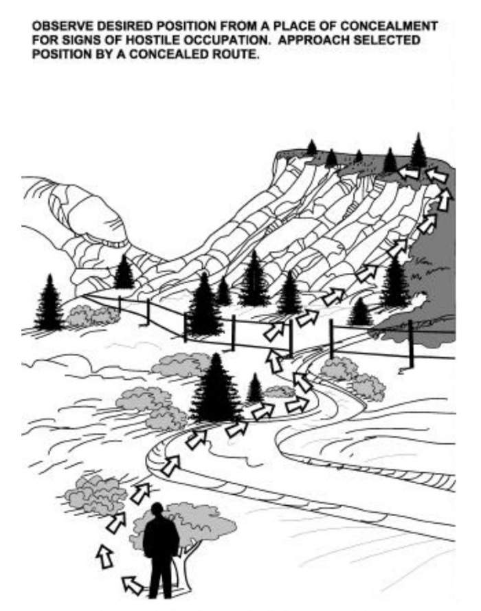
Sketch of a landscape with a silhouetted figure in the lower center standing behind a tree. In front of him are various shrubs, trees, a stream, and fence; behind the fence is an open, rocky escarpment with trees at the top of the bluff, which is the desired observation post. The scout looks for evidence of hostile occupation. White arrows show the route of the scout to the post, using native cover, as discussed in the preceding guidelines.

Figure 6-1. Method of Approaching an Observation Post.

Observing

Using all senses available, be particularly alert for movement, objects, sounds, and smells inappropriate to the surroundings. While observing, avoid all unnecessary movement. If observing from a building, keep back from doors and windows.

In daylight, look first at the ground nearest you. Begin observing close to your post and search a narrow strip 50 meters or less deep, going from right to left parallel to your front; then search from left to right a second and similar strip farther away but overlapping the first. Continue to observe until the entire field of view has been searched (see fig. 6-2 on page 6-2).

At night, use a night observation device. If one is not available, search the horizon with short, jerky movements, and short pauses. Look a little to one side of an object and then to the other. Lower the head close to the ground to view the object more clearly. Use low-powered field glasses to increase sight range.
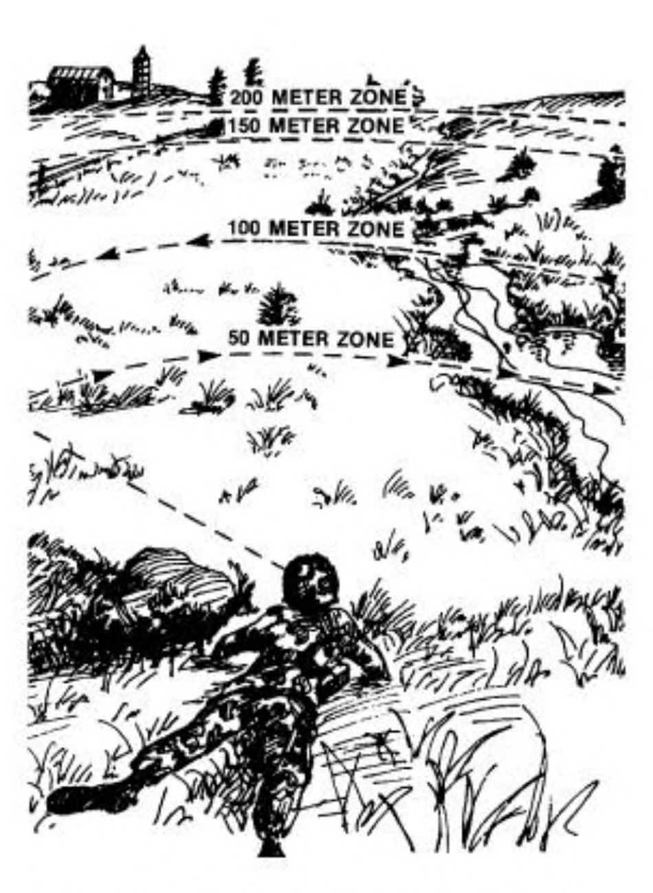
Sketch of a scout at the bottom of the image, lying on the ground facing the distant skyline. Various terrain features include open field, brush, a few trees, and at the horizon a barn and silo. Dotted lines in sequential arcs indicate 50 meters from the scout, 100 meters, 150 meters and 200 meters. A dashed line from the scout to the 50 meter zone indicates the direction the scout is looking.

Figure 6-2. Method of Searching Ground.

6002. REPORTING

It is imperative that the scout accurately and completely report who, where, when, and what was observed to the proper authority upon mission completion. In most cases, a scout will not be equipped with a radio.

Verbal Reports

Verbal reports should be made when writing is impractical, when the information is not complicated or when the enemy is likely to intercept a messenger carrying a written message.

Written Messages

Written messages, preferred to verbal reports, are recorded in message book blanks issued for that purpose (see fig. 6-3) and delivered to a higher authority as soon as possible. The NATO spot report (SPOTREP) should be reviewed as the written message is a NATO format.
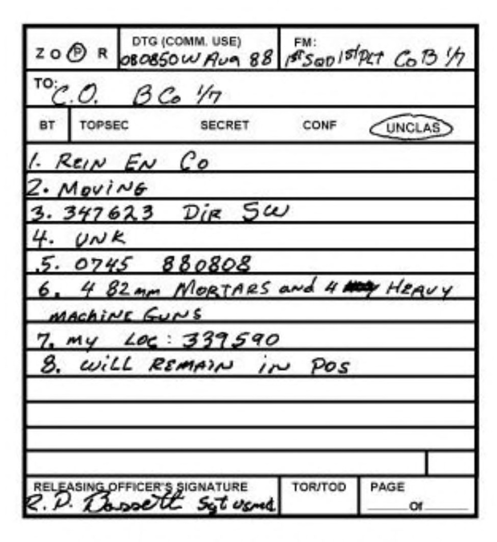
Sketch of a form completed by hand using NATO spot report format discussed in the text. On the top line, upper left, are the letters Z, O, P, R, with the 'P' circled; in the upper center section, the date and time are given, '080850W Aug 88'; at the upper right the report is from '1st SQD 1st PLT Co B 1/7'. The second line reads 'TO: C.O. B Co 1/7'; the third lines lists classifications: 'TOPSEC, SECRET, CONF and UNCLAS' with the last circled; below is the body of the message that reads: '1. REIN EN CO, 2. MOVING, 3. 347623 DIR SW, 4. UNK, 5. 0745 880808, 6. 4 82 MM MORTARS AND 4 HEAVY MACHINE GUNS, 7. MY LOC: 339590, 8. WILL REMAIN IN POS.' At the bottom, the form is signed by R. D. Bassett Sgt USMC.

Figure 6-3. Sample Field Message.

The message body is brief, accurate, and clear; facts and opinions are distinguished. If secondhand information is reported, its source is included. Reports include all information of value, first about the enemy, and then about the originator. Information about the enemy should cover⁠—

• Size and/or strength.

• Actions or activity.

• Location and direction of movement.

• Unit identification. (The designation of the enemy unit may be derived from unit markings, uniforms worn or through prisoner interrogation.)

• Time of observation.

• Equipment and weapons.

Messages are printed in block letters. Individual items of information are numbered and separated into paragraphs. If doubt exists as to message receipt by the commander, a summary of its contents is included in the next message. Information about the originator or writer should cover⁠—

• Location at the time of enemy observation (reference to an important terrain feature, by map coordinates, by the back azimuth from each of two definitely located points, or the back azimuth and distance from one known point).

• Intentions. (Remain in position? Continue on the mission? Take other action?)

The message is carefully reread and if possible read by another person to ensure understandability. If a messenger is used, the messenger must read and understand the message in order to answer any questions the commander might have.

Sketch

Information difficult to describe may be given accurately on a simple sketch. The sketch may give all the necessary information or it may be used to supplement a written message. A military sketch is generally one of two types: simple or panoramic. The simple sketch is easily made and read.

Figure 6-4 shows a simple sketch that has been included in the message itself. The sketch may be on a separate sheet of paper, but all of the necessary information must be contained in either the sketch, the message or both.

The panoramic sketch is a picture of the terrain’s elevation in perspective, as seen from one point of observation. Although a panoramic sketch is not difficult to create, skill and training are necessary to enhance usefulness. Figure 6-5 on page 6-4 illustrates how to make a panoramic sketch.

Overlay

The same information sent back to higher headquarters on the sketch may be sent on an overlay, if the sender and the person to whom the message is to be sent have copies of the same map. Figure 6-6 on page 6-6 illustrates a simple overlay. The overlay is drawn on transparent paper as follows:

• Orient the map and place it on a hard, flat surface.

• Place the transparent paper over the part of the map of the object or information to be transmitted and hold the paper in this position.

• Orient the overlay to the map by tracing in the intersecting grid lines at two opposite corners of the overlay. Write the correct number designation on the overlay. The cross made by the intersection is called a tick mark and enables the receiver to locate the exact area on the map covered by the overlay.

• Sketch the object seen or the information to be transmitted on the tracing paper (the sheet on top of the map) in the exact location it would appear on the map (the sheet underneath the tracing paper). Explanatory notes are annotated in the overlay’s margin, arrows point to the objectives.
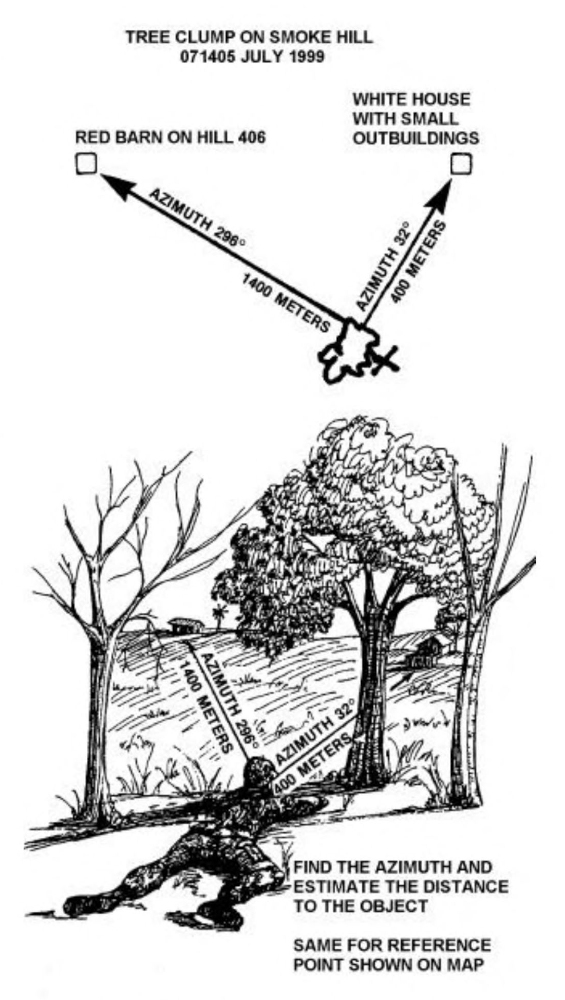
Two-part sketch entitled at the top 'TREE CLUMP ON SMOKE HILL 071405 JULY 1999'. A map below the title includes a box at upper left identified as 'RED BARN ON HILL 406'; box at upper right identified as 'WHITE HOUSE WITH SMALL OUTBUILDINGS'; and at lower right a ragged circle indicating a tree with an 'X' beside it, showing the scout's position. From his position are arrows pointing to the two buildings with azimuth direction and distance for each. Below the map is a sketch showing the same information. The scout is lying prone on the ground behind a large tree in the foreground. Arrows corresponding to the arrows on the upper map point to the barn and house on the skyline in the distance. Next to the scout is this text: FIND THE AZIMUTH AND ESTIMATE THE DISTANCE TO THE OBJECT.

Figure 6-4. Making a Simple Sketch.

• Indicate with an “X” and an appropriate explanation the position from which the observer saw the object or obtained information.

• Include title and scale of the map from which the overlay was made, date and hour the information was obtained, and signature of the observer on the overlay in the lower right-hand corner.
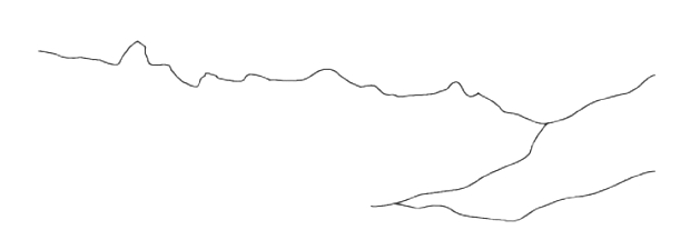
First of a 4-part sketch showing an outline of the horizon and shape of a hillside.

DRAW THE HORIZONTAL LINES OF A LANDSCAPE.
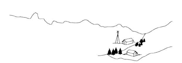
Second of 4-part sketch adding to the first sketch two buildings, a tower, and two clumps of trees.

PUT IN THE PROMINENT POINTS.

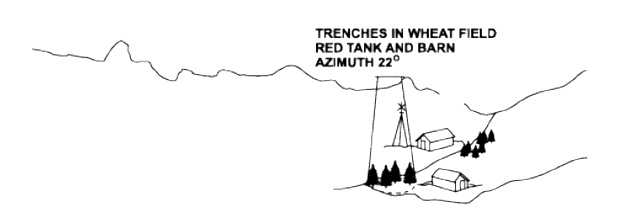
Third of 4-part sketch, adding notes above the prominent points: TRENCHES IN WHEAT FIELD, RED TANK AND BARN, AZIMUTH 22°.

PUT NOTES ABOVE SKETCH. PUT AZIMUTH FROM POSITION TO MOST PROMINENT POINT IN THE SKETCH.
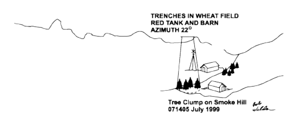
Fourth of 4-part sketch adding title at the bottom of the sketch: 'Tree Clump on Smoke Hill 071405 July 1999' signed 'Bob Wilder'.

GIVE SKETCH A TITLE. SHOW WHERE IT WAS MADE, THE DATE AND TIME, AND SIGN IT.

Figure 6-5. Panoramic Sketch.
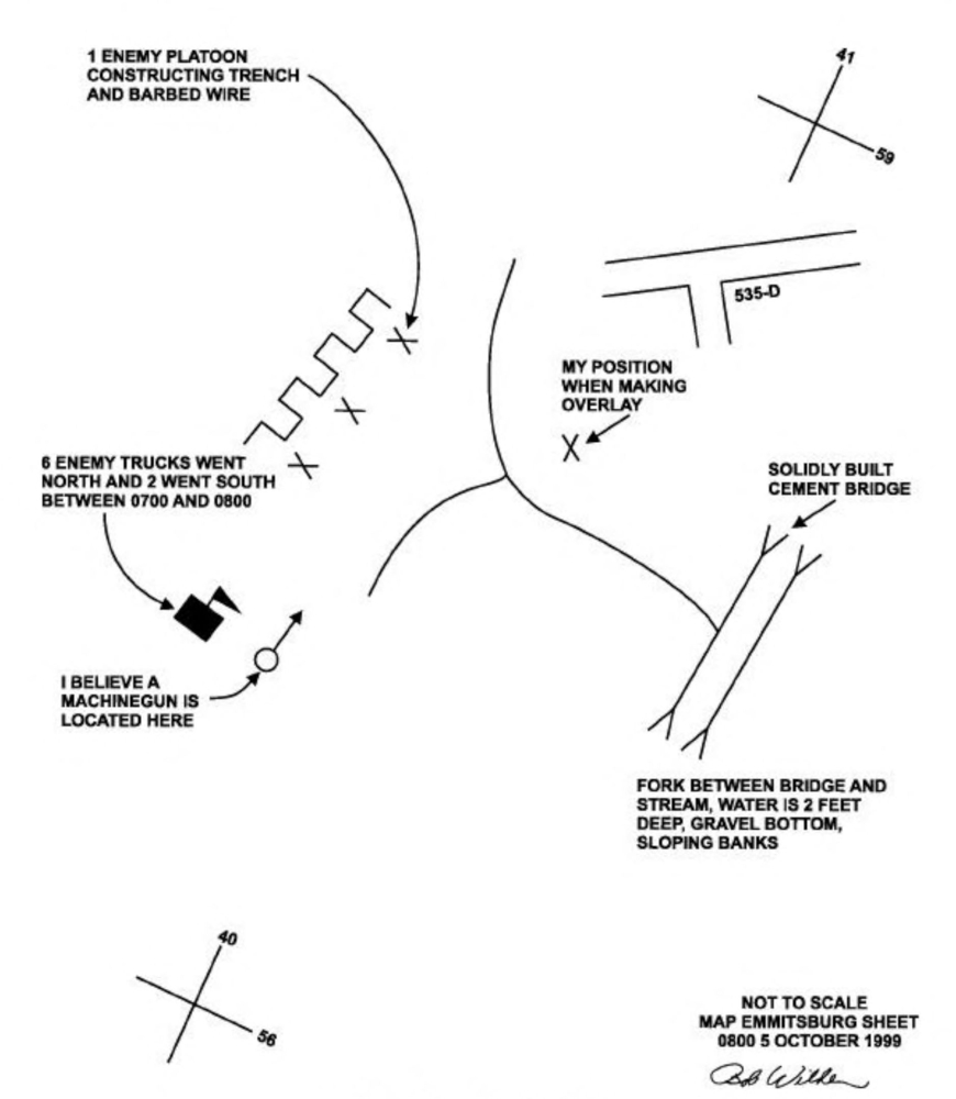
Overlay sketch identifies items with scout's comments. In the upper left, a crenellation with X's and note: '1 ENEMY PLATOON CONSTRUCTING TRENCH AND BARBED WIRE'. Below and left is a black square with a flag icon, with note: '6 ENEMY TRUCKS WENT NORTH AND 2 WENT SOUTH BETWEEN 0700 AND 0800'. Near the truck icon is a circle with an arrow and note: 'I BELIEVE A MACHINEGUN IS LOCATED HERE'. At the lower left is a cross hatch with the number 40 at the northeast and 56 at the southeast ends. In the upper right is a cross hatch with the number 41 at the northeast and 59 at the southeast ends. Below that is a T-intersection identified '535-D'. An X in the center is marked: 'MY POSITION WHEN MAKING OVERLAY'. Slightly below and to the right are two parallel lines with 'V' at each end identified as 'SOLIDLY BUILT CEMENT BRIDGE'. Below the bridge is a note: 'FORK BETWEEN BRIDGE AND STREAM, WATER IS 2 FEET DEEP, GRAVEL BOTTOM, SLOPING BANKS'. In the lower right corner is note: 'NOT TO SCALE, MAP EMMITSBURG SHEET, 0800 5 OCTOBER 1999', signed 'Bob Wilder'.

Figure 6-6. Simple Overlay.

Explore with AITake your curiosity a little further.

Reading settings