MODERN METHODS OF QUARRYING.
Reading edition
Mr. Wm. L. Saunders, for many years the engineer of the Ingersoll Rock Drill Co., and hence thoroughly familiar with modern quarrying practice, read a paper before the last meeting of the American Society of Civil Engineers on the above subject, containing many interesting points, given in the Engineering News, from which we abstract as follows.
As a preliminary to describing the new Knox system of quarrying, which even yet is not universally known among quarrymen, Mr. Saunders gives the following in regard to older methods:
The Knox system is a recent invention; no mention was made of it in the tenth census, and no description has yet been given of it in any publications on quarrying. The first work done by this method was in 1885, and at the close of that year 2 quarries had adopted it. In 1886 it was used in 20 quarries; in 1887 in 44, in 1888 in upward of 100, and at the present time about 300 quarries have adopted it. Its purpose is to release dimension stone from its place in the bed, by so directing an explosive force that it is made to cleave the rock in a prescribed line without injury. The system is also used for breaking up detached blocks of stone into smaller sizes.
Quarrymen have, ever since the introduction of blasting, tried to direct the blast so as to save stock. Holes drilled by hand are seldom round. The shape of the bit and their regular rotation while drilling usually produce a hole of somewhat triangular section. It was observed, many years ago, that when a blast was fired in a hand-drilled hole the rock usually broke in three directions, radiating from the points of the triangle in the hole. This led quarrymen to look for a means by which the hole might be shaped in accordance with a prescribed direction of cleavage.
The oldest sandstone quarries in America are those at Portland, Conn. It was from these quarries that great quantities of brownstone were shipped for buildings in New York. The typical "brownstone front" is all built of Portland stone. As the Portland quarries were carried to great depths the thickness of bed increased, as it usually does in quarries. With beds from 10 to 20 ft. deep, all of solid and valuable brownstone, it became a matter of importance that some device should be applied which would shear the stone from its bed without loss of stock and without the necessity of making artificial beds at short distances. A system was adopted and used successfully for a number of years which comprised the drilling of deep holes from 10 to 12 in. in diameter, and charging them with explosives placed in a canister of peculiar shape. The drilling of this hole is so interesting as to warrant a passing notice. The system was similar to that followed with the old fashioned drop drill. The weight of the bit was the force which struck the blow, and this bit was simply raised or lowered by a crank turned by two men at the wheel. The bit resembled a broad ax in shape, in that it was extremely broad, tapering to a sharp point, and convex along the edge.
FIG. 1
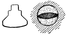
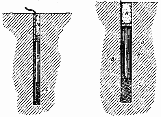
Fig. 1 illustrates in section one of the Portland drills, and a drill hole with the canister containing the explosive in place. The canister was made of two curved pieces of sheet tin with soldered edges, cloth or paper being used at the ends. It was surrounded with sand or earth, so that the effect of the blast was practically the same as though the hole were drilled in the shape of the canister. In other words, the old Portland system was to drill a large, round hole, put in a canister, and then fill up a good part of the hole. Were it possible to drill the hole in the shape of the canister, it would obviously save a good deal of work which had to be undone. The Portland system was, therefore, an extravagant one, but the results accomplished were such as to fully warrant its use. Straight and true breaks were made, following the line of the longer axis of the canister section, as in Fig. 2.
FIG. 2
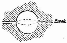
It was found that with the old Portland canister two breaks might be made at right angles by a single blast, when using a canister shaped like a square prism. In some of the larger blasts, where blocks weighing in the neighborhood of 2,000 tons were sheared on the bed, two holes as deep as 20 ft. were drilled close together. The core between the holes was then clipped out and large canisters measuring 2 ft. across from edge to edge were used.
In regard to another of the older systems of blasting, known as Lewising, Mr. Saunders says:
A Lewis hole is made by drilling two or three holes close together and parallel with each other, the partitions between the holes being broken down by using what is known as a broach. Thus a wide hole or groove is formed in which powder is inserted, either by ramming it directly in the hole, or by puling it in a canister, shaped somewhat like the Lewis hole trench. A complex Lewis hole is the combination of 3 drill holes, while a compound Lewis hole contains 4 holes. Lewising is confined almost entirely to granite. In some cases a series of Lewis holes is put in along the bench at distances of 10 and 25 ft. apart, or even greater, each Lewis hole being situated equidistant from the face of the bench. The holes are blasted simultaneously by the electric battery.
After noting another system used to a limited extent, and not to be commended, viz., the use of inverted plugs and feathers (the plugs and feathers being inserted as a sort of tamping which the blast drives upward to split the rock), Mr. Saunders continues in substance as follows:
It is thus seen that the "state of the art" has been progressive, though it was imperfect. Mr. Sperr, in his reference to this subject, made in the report of the tenth census, says: "The influence of the shape of the drill hole upon the effects of the blast does not seem to be generally known, and a great waste of material necessarily follows." This was written but a few years before the introduction of the new system, and it is doubtless true that attention was thus widely directed to the conspicuous waste, due to a lack of knowledge of the influence of the shape of a drill hole on the effect of a blast. The system developed by Mr. Knox practically does all and more than was done by the old Portland system, and it does it at far less expense. It can best be described by illustrations.
FIG. 3, 4, 5 and 6
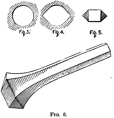
Fig. 3 is a round hole drilled either by hand or otherwise, preferably otherwise, because an important point is to get it round. Fig. 4 is the improved form of hole, and this is made by inserting a reamer, Figs. 5 and 6, into the hole in the line of the proposed fracture, thus cutting two V-shaped grooves into the walls of the hole. The blacksmith tools for dressing the reamers are shown in Fig. 7. The usual method of charging and tamping a hole in using the new system is shown in Fig. 8. The charge of powder is shown at C, the air space at B and the tamping at A. Fig. 9 is a special hole for use in thin beds of rock. The charge of powder is shown at C, the rod to sustain tamping at D, air space at BB, and tamping at A.
FIG. 7
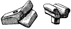
Let us assume that we have a bluestone quarry, in which we may illustrate the simplest application of the new system. The sheet of stone which we wish to shear from place has a bed running horizontally at a depth of say 10 ft. One face is in front and a natural seam divides the bed at each end at the walls of the quarry. We now have a block of stone, say 50 ft. long, with all its faces free except one—that opposite and corresponding with the bench. One or more of the specially formed holes are put in at such depth and distance from each other and from the bench as may be regulated by the thickness, strength and character of the rock. No man is so good a judge of this as the quarry foreman who has used and studied the effect of this system in his quarry. Great care should be taken to drill the holes round and in a straight line. In sandstone of medium hardness these holes may be situated 10, 12 or 15 ft. apart. If the bed is a tight one the hole should be run entirely through the sheet and to the bed; but with an open free bed holes of less depth will suffice.
FIG. 8 and 9
The reamer should now be used and driven by hand. Several devices have been applied to rock drills for reaming the hole by machinery while drilling; that is, efforts have been made to combine the drill and the reamer. Such efforts have met with only partial success. The perfect alignment of the reamer is so important that where power is used this point is apt to be neglected. It is also a well known fact that the process of reaming by hand is not a difficult or a slow one. The drilling of the hole requires the greatest amount of work. After this has been done it is a simple matter to cut the V-shaped grooves. The reamer should be applied at the center, that is, the grooves should be cut on the axis or full diameter of the hole. The gauge of the reamer should be at least 1½ diameters. Great care should be taken that the reamer does not twist, as the break may be thereby deflected; and the reaming must be done also to the full depth of the hole.
The hole is now ready for charging. The powder should be a low explosive, like black or Judson powder or other explosives which act slowly. No definite rule can be laid down as to the amount of powder to be used, but it should be as small as possible. Very little powder is required in most rocks. Hard and fine grained stone requires less powder than soft stone. Mr. Knox tells of a case which came under his observation, where a block of granite "more than 400 tons weight, split clear in two with 13 oz. of FF powder." He compares this with a block of sandstone of less than 100 tons weight "barely started with 2½ lb. of the same grade of powder, and requiring a second shot to remove it."
It is obvious that enough powder must be inserted in the hole to produce a force sufficient to move the entire mass of rock on its bed. In some kinds of stone, notably sandstone, the material is so soft that it will break when acted upon by the force necessary to shear the block. In cases of this kind a number of holes should be drilled and fired simultaneously by the electric battery. In such work it is usual to put in the holes only 4 or 5 ft. apart. The powder must, of course, be provided with a fuse or preferably a fulminating cap. It is well to insert the cap at or near the bottom of the cartridge, as shown in Figs. 8 and 9.
After the charge the usual thing to do is to insert tamping. In the improved form of hole the tamping should not he put directly upon the powder, but an air space should be left, as shown at B, Fig. 8. The best way to tamp, leaving an air space, is first to insert a wad, which may be of oakum, hay, grass, paper or other similar material. The tamping should be placed from 6 to 12 in. below the mouth of the hole. In some kinds of stone a less distance will suffice, and as much air space as practicable should intervene between the explosive and the tamping. If several holes are used on a line they should be connected in series and blasted by electricity. The effect of the blast is to make a vertical seam connecting the holes, and the entire mass of rock is sheared several inches or more.
The philosophy of this new method of blasting is simple, though a matter of some dispute. The following explanation has been given. See Fig. 10.
FIG. 11
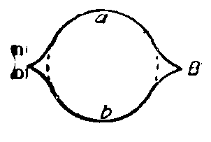
"The two surfaces, a and b, being of equal area, must receive an equal amount of the force generated by the conversion of the explosive into gas. These surfaces being smooth and presenting no angle between the points, A and B, they furnish no starting point for a fracture, but at these points the lines meet at a sharp angle including between them a wedge-shaped space. The gas acting equally in all directions from the center is forced into the two opposite wedge-shaped spaces, and the impact being instantaneous the effect is precisely similar to that of two solid wedges driven from the center by a force equally prompt and energetic. All rocks possess the property of elasticity in a greater or less degree, and this principle being excited to the point of rupture at the points, A and B, the gas enters the crack and the rock is split in a straight line simply because under the circumstances it cannot split in any other way."
Another theory which is much the same in substance is then given, and after some general discussion of the theory of the action of the forces under the several systems, the paper continues:
The new form of hole is, therefore, almost identical in principle with the old Portland canister, except that it has the greater advantage of the V-shaped groove in the rock, which serves as a starting point for the break. It is also more economical than the Portland canister, in that it requires less drilling and the waste of stone is less. It is, therefore, not only more economical than any other system of blasting, but it is more certain, and in this respect it is vastly superior to any other blasting system, because stone is valuable, and anything which adds to the certainty of the break also adds to the profit of the quarryman.
It is doubtless true that, notwithstanding the greater area of pressure in the new form of hole, the break would not invariably follow the prescribed line but for the V-shaped groove which virtually starts it. A bolt, when strained, will break in the thread whether this be the smallest section or not, because the thread is the starting point for the break. A rod of glass is broken with a slight jar provided a groove has been filed in its surface. Numerous other instances might be cited to prove the value of the groove. Elasticity in rock is a pronounced feature, which varies to a greater or less extent; but it is always more or less present. A sandstone has recently been found which possesses the property of elasticity to such an extent that it may be bent like a thin piece of steel. When a blast is made in the new form of hole the stone is under high tension, and being elastic it will naturally pull apart on such lines of weakness as grooves, especially when they are made, as is usually the case in this system, in a direction at right angles with the lines of least resistance.
Horizontal holes are frequently put in and artificial beds made by "lofting." In such cases where the rock has a "rift" parallel with the bed, one hole about half way through is sufficient for a block about 15 ft. square, but in "liver" rock the holes must be drilled nearly through the block and the size of the block first reduced.
A more difficult application of the system, and one requiring greater care in its successful use, is where the block of stone is so situated that both ends are not free, one of them being solidly fixed in the quarry wall. A simple illustration of a case of this kind is a stone step on a stairway which leads up and along a wall, Fig. 11. Each step has one end fixed to the wall and the other free. Each step is also free on top, on the bottom and on the face, but fixed at the back. We now put one of the new form of holes in the corner at the junction of the step and the wall. The shape of the hole is as shown in Fig. 12.
FIG. 11
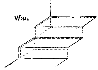
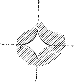
It is here seen that the grooves are at right angles with each other, and the block of stone is sheared by a break made opposite and parallel with the bench, as in the previous case, and an additional break made at right angles with the bench and at the fixed end of the block. Sometimes a corner break is made by putting in two of the regular V-shaped holes in the lines of the proposed break and without the use of the corner hole. A useful application of this system is in splitting up large masses of loose stone. For this purpose the V-shaped grooves are sometimes cut in four positions and breaks are made in four directions radiating from the center of the hole as shown in Fig. 12. In this way a block is divided into four rectangular pieces.
FIG. 12
Though the new system is especially adapted to the removal of heavy masses of rock, yet it has been applied with success in cases where several light beds overlie each other. In one such instance 10 sheets, measuring in all only 6 ft., were broken by a blast, but in cases of this kind the plug and feather process applies very well, and the new system, when used, must be in the hands of an expert, or the loss will be serious.
Referring again to our stone step, let us imagine a case where this stairway runs between two walls. We have here each step fixed at each end and free only on the top, the bottom, and one face. Let us assume that there is a back seam, that is, that the step is not fixed at the back. In a quarry, this seam, unless a natural one, should be made by a channeling machine. In order to throw this step put of place it must be cut off at both ends, and for this purpose the V-shaped holes are put in at right angles to the face. It is well, however, to put the first two holes next the back seam in a position where the grooves will converge at the back so as to form a sort of key, which serves a useful purpose in removing the block after the blast. In quarries where there are no horizontal beds a channeling machine should be used to free the block on all sides and to a suitable depth, and then the ledge may be "lofted" by holes placed horizontally.
Where "pressure" exists in quarries, the new system has certain limitations. After determining the line of "pressure" it is only practicable to use the system directly on the line of thrust, or at right angles to it. It is much better, however, to release the "pressure" from the ledge by channeling, after which a single end may be detached by a Knox blast. It is well to bear in mind that the holes should invariably be of small diameter. In no case should the diameter of a hole be over 1½ in. in any kind of rock. This being the case, the blocks of stone are delivered to the market with but little loss in measurement. It is a noticeable fact that stone quarried by the new system shows very little evidence of drill marks, for the faces are frequently as true as though cut with a machine.
A further gain is the safety of the system. The blasting is light and is confined entirely within the holes. No spalls or fragments are thrown from the bast.
The popular idea that the system is antagonistic to the channeling process is a mistaken one. There are, of course, some quarries which formerly used channeling machines without this system, but which now do a large part of the work by blasting. Instances, however, are rare where the system has replaced the channeler. The two go side by side, and an intelligent use of the new system in most quarries requires a channeling machine. There are those who may tell of stone that has been destroyed by a blast on the new system, but investigation usually shows that either the work was done by an inexperienced operator, or an effort was made to do too much.
A most interesting illustration of the value of this system, side by side with the channeler, is shown in the northern Ohio sandstone quarries. A great many channeling machines are in use there, working around the new form of holes, and when used together in an intelligent and careful manner, the stone is quarried more cheaply than by any other process that has yet been devised.
To a limited extent the system has been used in slate. The difficulty is that most of the slate quarries are in solid ledges, where no free faces or beds exist; but it has been used with success in a slate quarry at Cherryville, Pa., since 1888. Among notable blasts made by this system are the following: At the mica schist quarries, at Conshohocken, Pa., a hole 1½ in. in diameter was drilled in a block which was 27 ft. long, 15 ft. wide and 6 ft. thick. The blast broke the stone across the "rift," only 8 oz. of black powder being used. At the Portland, Conn., quarries a single blast was fired by electricity, 15 holes being drilled with 2 lb. of coarse No. C powder in each hole, and a rock was removed 110 ft. long, 20 ft. wide and 11 ft. thick, containing 24,200 cu. ft., or about 2,400 tons, the fracture being perfectly straight. This large mass of stone was moved out about 2 in. without injury to itself or the adjoining rock.
Another blast at Portland removed 3,300 tons a distance of 4 in. Seventeen holes were drilled, using 2 lb. of powder in each hole, the size of the block being 150 × 20 × 11 ft. In a Lisbon, O., quarry a block of sandstone 200 ft. long, 28 ft. wide and 15 ft. thick was moved about ½ in. by a blast. This block was also afterward cut up by this system in blocks 6 ft. square. A sandstone bowlder 70 ft. long, average width 50 ft., average thickness 13 ft., was embedded in the ground to a depth of about 7 ft. A single hole 8 ft. deep was charged with 20 oz. of powder and the rock was split in a straight line from end to end and entirely to the bottom. A ledge of sandstone open on its face and two ends, 110 × 13 × 8 ft., was moved by a blast about 3 in. without wasting a particle of rock, 8 holes being used, drilled by three men in just one day, and 15 oz. of powder being used in each hole. A sandstone ledge, open on the face and end only, 200 × 28 × 15 ft., containing 84,000 cu. ft. stone, was moved ½ in. by 25 holes, each containing 1 lb. of powder.