THE ELECTROMAGNET.1
Reading edition
THE ELECTROMAGNET.1
By Professor SILVANUS P. THOMPSON, D.Sc., B.A., M.I.E.E.
III.
RESEARCHES OF PROFESSOR HUGHES.
FIG. 51.—HUGHES' ELECTROMAGNET.
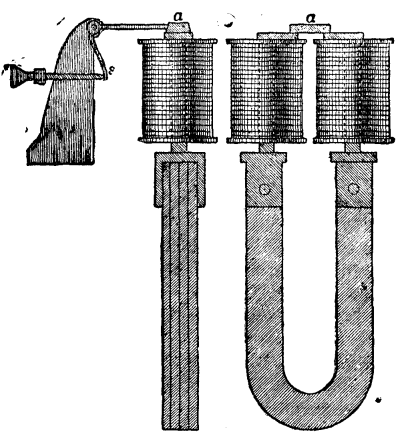
His object was to find out the best form of electromagnet, the best distance between the poles, and the best form of armature for the rapid work required in Hughes' printing telegraphs. One word about Hughes' magnets. This diagram (Fig. 51) shows the form of the well known Hughes' electromagnet. I feel almost ashamed to say those words "well known," because on the Continent everybody knows what you mean by a Hughes' electromagnet. In England scarcely anyone knows what you mean. Englishmen do not even know that Professor Hughes has invented a special form of electromagnet. Hughes' special form is this: A permanent steel magnet, generally a compound one, having soft iron pole pieces, and a couple of coils on the pole pieces only. As I have to speak of Hughes' special contrivance among the mechanisms that will occupy our attention later on, I only now refer to this magnet in one particular. If you wish a magnet to work rapidly, you will secure the most rapid action, not when the coils are distributed all along, but when they are heaped up near, not necessarily entirely on, the poles. Hughes made a number of researches to find out what the right length and thickness of these pole pieces should be. It was found an advantage not to use too thin pole pieces, otherwise the magnetism from the permanent magnet did not pass through the iron without considerable reluctance, being choked by insufficiency of section: also not to use too thick pieces, otherwise they presented too much surface for leakage across from one to the other. Eventually a particular length was settled upon, in proportion about six times the diameter, or rather longer. In the further researches that Hughes made he used a magnet of shorter form, not shown here, more like those employed in relays, and with an armature from 2 to 3 millimeters thick, 1 centimeter wide and 5 centimeters long. The poles were turned over at the top toward one another. Hughes tried whether there was any advantage in making those poles approach one another, and whether there was any advantage in having as long an armature as 5 centimeters. He tried all the different kinds, and plotted out the results of observations in curves, which could be compared and studied. His object was to ascertain the conditions which would give the strongest pull, not with a steady current, but with such currents as were required for operating his printing telegraph instruments; currents which lasted but one to twenty hundredths of a second. He found it was decidedly an advantage to shorten the length of the armature, so that it did not protrude far over the poles. In fact, he got a sufficient magnetic circuit to secure all the attractive power that he needed, without allowing as much chance of leakage as there would have been had the armature extended a longer distance over the poles. He also tried various forms of armature having very various cross sections.
POSITION AND FORM OF ARMATURE.
In one of Du Moncel's papers on electromagnets2 you will also find a discussion on armatures, and the best forms for working in different positions. Among other things in Du Moncel you will find this paradox: that whereas using a horseshoe magnet with fat poles, and a flat piece of soft iron for armature, it sticks on far tighter when put on edgeways; on the other hand, if you are going to work at a distance, across air, the attraction is far greater when it is set flatways. I explained the advantage of narrowing the surfaces of contact by the law of traction, B², coming in. Why should we have for action at a distance the greater advantage from placing the armature flatway to the poles? It is simply that you thereby reduce the reluctance offered by the air gap to the flow of the magnetic lines. Du Moncel also tried the difference between round armatures and flat ones, and found that a cylindrical armature was only attracted about half as strongly as a prismatic armature having the same surface when at the same distance. Let us examine this fact in the light of the magnetic circuit. The poles are flat. You have at a certain distance away a round armature; there is a certain distance between its nearest side and the polar surfaces. If you have at the same distance away a flat armature having the same surface, and, therefore, about the same tendency to leak, why do you get a greater pull in this case than in that? I think it is clear that if they are at the same distance away, giving the same range of motion, there is a greater magnetic reluctance in the case of the round armature, although there is the same periphery, because, though the nearest part of the surface is at the prescribed distance, the rest of the under surface is farther away; so that the gain found in substituting an armature with a flat surface is a gain resulting from the diminution in the resistance offered by the air gap.
POLE PIECES ON HORSESHOE MAGNETS.
Another of Du Moncel's researches3 relates to the effect of polar projections or shoes—movable pole pieces, if you like—upon a horseshoe electromagnet. The core of this magnet was of round iron 4 centimeters in diameter, and the parallel limbs were 10 centimeters long and 6 centimeters apart. The shoes consisted of two flat pieces of iron slotted out at one end, so that they could be slid along over the poles and brought nearer together. The attraction exerted on a flat armature across air gaps 2 millimeters thick was measured by counterpoising. Exciting this electromagnet with a certain battery, it was found that the attraction was greatest when the shoes were pushed to about 15 millimeters, or about one-quarter of the interpolar distance, apart. The numbers were as follows:
Distance between shoes. Millimeters. Attraction, in grammes.
2 900
10 1,012
15 1,025
25 965
40 890
60 550
With a stronger battery the magnet without shoes had an attraction of 885 grammes, but with the shoes 15 millimeters apart, 1,195 grammes. When one pole only was employed, the attraction, which was 88 grammes without a shoe, was diminished by adding a shoe to 39 grammes!
CONTRAST BETWEEN ELECTROMAGNETS AND PERMANENT MAGNETS.
Now I want particularly to ask you to guard against the idea that all these results obtained from electromagnets are equally applicable to permanent magnets of steel; they are not, for this simple reason. With an electromagnet, when you put the armature near, and make the magnetic circuit better, you not only get more magnetic lines going through that armature, but you get more magnetic lines going through the whole of the iron. You get more magnetic lines round the bend when you put an armature on to the poles, because you have a magnetic circuit of less reluctance with the same external magnetizing power in the coils acting around it. Therefore, in that case, you will have a greater magnetic flux all the way round. The data obtained with the electromagnet (Fig. 42), with the exploring coil, C, on the bend of the core, where the armature was in contact, and when it was removed are most significant. When the armature was present it multiplied the total magnetic flow tenfold for weak currents and nearly threefold for strong currents. But with a steel horseshoe, magnetized once for all, the magnetic lines that flow around the bend of the steel are a fixed quantity, and, however much you diminish the reluctance of the magnetic circuit, you do not create or evoke any more. When the armature is away the magnetic lines arch across, not at the ends of the horseshoe only, but from its flanks; the whole of the magnetic lines leaking somehow across the space. Where you have put the armature on, these lines, instead of arching out into space as freely as they did, pass for the most part along the steel limbs and through the iron armature. You may still have a considerable amount of leakage, but you have not made one line more go through the bent part. You have absolutely the same number going through the bend with the armature off as with the armature on. You do not add to the total number by reducing the magnetic reluctance, because you are not working under the influence of a constantly impressed magnetizing force. By putting the armature on to a steel horseshoe magnet you only collect the magnetic lines, you do not multiply them. This is not a matter of conjecture. A group of my students have been making experiments in the following way: They took this large steel horseshoe magnet (Fig. 52), the length of which, from end to end, through the steel, is 42½ inches. A light, narrow frame was constructed so that it could be slipped on over the magnet, and on it were wound 30 turns of fine wire, to serve as an exploring coil. The ends of this coil were carried to a distant part of the laboratory, and connected to a sensitive ballistic galvanometer. The mode of experimenting is as follows:
The coil is slipped on over the magnet (or over its armature) to any desired position. The armature of the magnet is placed gently upon the poles, and time enough is allowed to elapse for the galvanometer needle to settle to zero. The armature is then suddenly detached. The first swing measures the change, due to removing the armature, in the number of magnetic lines that pass through the coil in the particular position.
FIG. 52.—EXPERIMENT WITH PERMANENT MAGNET.
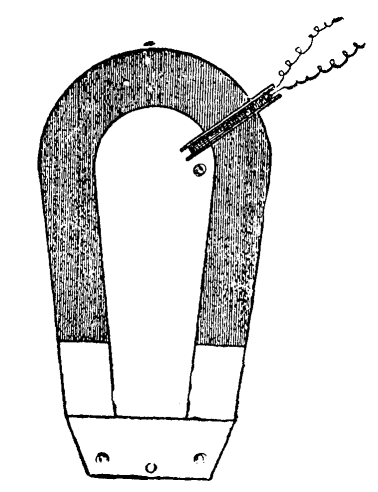
I will roughly repeat the experiment before you: The spot of light on the screen is reflected from my galvanometer at the far end of the table. I place the exploring coil just over the pole, and slide on the armature; then close the galvanometer circuit. Now I detach the armature, and you observe the large swing. I shift the exploring coil, right up to the bend; replace the armature; wait until the spot of light is brought to rest at the zero of the scale. Now, on detaching the armature, the movement of the spot of light is quite imperceptible. In our careful laboratory experiments, the effect was noticed inch by inch all along the magnet. The effect when the exploring coil was over the bend was not as great as 1-3000th part of the effect when the coil was hard up to the pole. We are, therefore, justified in saying that the number of magnetic lines in a permanently magnetized steel horseshoe magnet is not altered by the presence or absence of the armature.
You will have noticed that I always put on the armature gently. It does not do to slam on the armature; every time you do so, you knock some of the so-called permanent magnetism out of it. But you may pull off the armature as suddenly as you like. It does the magnet good rather than harm. There is a popular superstition that you ought never to pull off the keeper of a magnet suddenly. On investigation, it is found that the facts are just the other way. You may pull off the keeper as suddenly as you like, but you should never slam it on.
From these experimental results I pass to the special design of electromagnets for special purposes.
ELECTROMAGNETS FOR MAXIMUM TRACTION.
These have already been dealt with in the preceding lecture; the characteristic feature of all the forms suitable for traction being the compact magnetic circuit.
Several times it has been proposed to increase the power of electromagnets by constructing them with intermediate masses of iron between the central core and the outside, between the layers of windings. All these constructions are founded on fallacies. Such iron is far better placed either right inside the coils or right outside them, so that it may properly constitute a part of the magnetic circuit. The constructions known as Camacho's and Cance's, and one patented by Mr. S.A. Varley, in 1877, belonging to this delusive order of ideas, are now entirely obsolete.
Another construction which is periodically brought forward as a novelty is the use of iron windings of wire or strip in place of copper winding. The lower electric conductivity of iron, as compared with copper, makes such a construction wasteful of exciting power. To apply equal magnetizing power by means of an iron coil implies the expenditure of about six times as many watts as need be expended if the coil is of copper.
ELECTROMAGNETS FOR MAXIMUM RANGE OF ATTRACTION.
We have already laid down the principle which will enable us to design electromagnets to act at a distance. We want our magnet to project, as it were, its force across the greatest length of air gap. Clearly, then, such a magnet must have a very large magnetizing power, with many ampere turns upon it, to be able to make the required number of magnetic lines pass across the air resistance. Also it is clear that the poles must not be too close together for its work, otherwise the magnetic lines at one pole will be likely to curl round and take short cuts to the other pole. There must be a wider width between the poles than is desirable in electromagnets for traction.
ELECTROMAGNETS OF MINIMUM WEIGHT.
In designing an apparatus to put on board a boat or a balloon, where weight is a consideration of primary importance, there is again a difference. There are three things that come into play—iron, copper, and electric current. The current weighs nothing, therefore, if you are going to sacrifice everything else to weight, you may have comparatively little iron, but you must have enough copper to be able to carry the electric current; and under such circumstances you must not mind heating your wires nearly red hot to pass the biggest possible current. Provide as little copper as you conveniently can, sacrificing economy in that case to the attainment of your object; but, of course, you must use fireproof material, such as asbestos, for insulating, instead of cotton or silk.