A USEFUL GUIDING PRINCIPLE.
Reading edition
In all cases of design there is one leading principle which will be found of great assistance, namely, that a magnet always tends so to act as though it tried to diminish the length of its magnetic circuit. It tries to grow more compact. This is the reverse of that which holds good with an electric current. The electric circuit always tries to enlarge itself, so as to inclose as much space as possible, but the magnetic circuit always tries to make itself as compact as possible. Armatures are drawn in as near as can be, to close up the magnetic circuit. Many two-pole electromagnets show a tendency to bend together when the current is turned on. One form in particular, which was devised by Ruhmkorff for the purpose of repeating Faraday's celebrated experiment on the magnetic rotation of polarized light, is liable to this defect. Indeed, this form of electromagnet is often designed very badly, the yoke being too thin, both mechanically and magnetically, for the purpose which it has to fulfill.
Here is a small electric bell, constructed by Wagener, of Wiesbaden, the construction of which illustrates this principle. The electromagnet, a horseshoe, lies horizontally; its poles are provided with protruding curved pins of brass. Through the armature are drilled two holes, so that it can be hung upon the two brass pins; and when so hung up it touches the ends of the iron cores just at one edge, being held from more perfect contact by a spring. There is no complete gap, therefore, in the magnetic circuit. When the current comes and applies a magnetizing power, it finds the magnetic circuit already complete in the sense that there are no absolute gaps. But the circuit can be bettered by tilting the armature to bring it flat against the polar ends, that being indeed the mode of motion. This is a most reliable and sensitive pattern of bell.
FIG. 53.—ELECTROMAGNETIC POP-GUN.
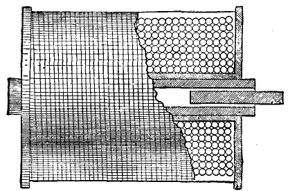
Electromagnetic Pop-gun.—Here is another curious illustration of the tendency to complete the magnetic circuit. Here is a tubular electromagnet (Fig. 53), consisting of a small bobbin, the core of which is an iron tube about two inches long. There is nothing very unusual about it; it will stick on, as you see, to pieces of iron when the current is turned on. It clearly is an ordinary electromagnet in that respect. Now suppose I take a little round rod of iron, about an inch long, and put it into the end of the tube, what will happen when I turn on my current? In this apparatus as it stands, the magnetic circuit consists of a short length of iron, and then all the rest is air. The magnetic circuit will try to complete itself, not by shortening the iron, but by lengthening it; by pushing the piece of iron out so as to afford more surface for leakage. That is exactly what happens; for, as you see, when I turn on the current, the little piece of iron shoots out and drops down. You see that little piece of iron shoot out with considerable force. It becomes a sort of magnetic popgun. This is an experiment which has been twice discovered. I found it first described by Count Du Moncel, in the pages of La Lumiere Electrique, under the name of the "pistolet electromagnetique;" and Mr. Shelford Bidwell invented it independently. I am indebted to him for the use of this apparatus. He gave an account of it to the Physical Society, in 1885, but the reporter missed it, I suppose, as there is no record in the society's proceedings.
ELECTROMAGNETS FOR USE WITH ALTERNATING CURRENTS.
When you are designing electromagnets for use with alternating currents, it is necessary to make a change in one respect, namely, you must so laminate the iron that internal eddy currents shall not occur; indeed, for all rapid-acting electromagnetic apparatus it is a good rule that the iron must not be solid. It is not usual with telegraphic instruments to laminate them by making up the core of bundles of iron plates or wires, but they are often made with tubular cores, that is to say, the cylindrical iron core is drilled with a hole down the middle, and the tube so formed is slit with a saw cut to prevent the circulation of currents in the substance of the tube. Now when electromagnets are to be employed with rapidly alternating currents, such as are used for electric lighting, the frequency of the alternations being usually about 100 periods per second, slitting the cores is insufficient to guard against eddy currents; nothing short of completely laminating the cores is a satisfactory remedy. I have here, thanks to the Brush Electric Engineering Company, an electromagnet of the special form that is used in the Brush arc lamp when required for the purpose of working in an alternating current circuit. It has two bobbins that are screwed up against the top of an iron box at the head of the lamp. The iron slab serves as a kind of yoke to carry the magnetism across the top. There are no fixed cores In the bobbins, which are entered by the ends of a pair of yoked plungers. Now in the ordinary Brush lamp for use with a steady current, the plungers are simply two round pieces of iron tapped into a common yoke; but for alternate current working this construction must not be used, and instead a U-shaped double plunger is used, made up of laminated iron, riveted together. Of course it is no novelty to use a laminated core; that device, first used by Joule, and then by Cowper, has been repatented rather too often during the past fifty years to be considered as a recent invention.
The alternate rapid reversals of the magnetism in the magnetic field of an electromagnet, when excited by alternating electric currents, sets up eddy currents in every piece of undivided metal within range. All frames, bobbin tubes, bobbin ends, and the like, must be most carefully slit, otherwise they will overheat. If a domestic flat iron is placed on the top of the poles of a properly laminated electromagnet, supplied with alternating currents, the flat iron is speedily heated up by the eddy currents that are generated internally within it. The eddy currents set up by induction in neighboring masses of metal, especially in good conducting metals such as copper, give rise to many curious phenomena. For example, a copper disk or copper ring placed over the pole of a straight electromagnet so excited is violently repelled. These remarkable phenomena have been recently investigated by Professor Elihu Thomson, with whose beautiful and elaborate researches we have lately been made conversant in the pages of the technical journals. He rightly attributes many of the repulsion phenomena to the lag in phase of the alternating currents thus induced in the conducting metal. The electromagnetic inertia, or self-inductive property of the electric circuit, causes the currents to rise and fall later in time than the electromotive forces by which they are occasioned. In all such cases the impedance which the circuit offers is made up of two things—resistance and inductance. Both these causes tend to diminish the amount of current that flows, and the inductance also tends to delay the flow.
ELECTROMAGNETS FOR QUICKEST ACTION.
I have already mentioned Hughes' researches on the form of electromagnet best adapted for rapid signaling. I have also incidentally mentioned the fact that where rapidly varying currents are employed, the strength of the electric current that a given battery can yield is determined not so much by the resistance of the electric circuit as by its electric inertia. It is not a very easy task to explain precisely what happens to an electric circuit when the current is turned on suddenly. The current does not suddenly rise to its full value, being retarded by inertia. The ordinary law of Ohm in its simple form no longer applies; one needs to apply that other law which bears the name of the law of Helmholtz, the use of which is to give us an expression, not for the final value of the current, but for its value at any short time, t, after the current has been turned on. The strength of the current after a lapse of a short time, t, cannot be calculated by the simple process of taking the electromotive force and dividing it by the resistance, as you would calculate steady currents.
In symbols, Helmholtz's law is:
it = E/R ( 1 - e- (R/L)t )
In this formula it means the strength of the current after the lapse of a short time t; E is the electromotive force; R, the resistance of the whole circuit; L, its coefficient of self-induction; and e the number 2.7183, which is the base of the Napierian logarithms. Let us look at this formula; in its general form it resembles Ohm's law, but with a new factor, namely, the expression contained within the brackets. The factor is necessarily a fractional quantity, for it consists of unity less a certain negative exponential, which we will presently further consider. If the factor within brackets is a quantity less than unity, that signifies that it will be less than E ÷ R. Now the exponential of negative sign, and with negative fractional index, is rather a troublesome thing to deal with in a popular lecture. Our best way is to calculate some values, and then plot it out as a curve. When once you have got it into the form of a curve, you can begin to think about it, for the curve gives you a mental picture of the facts that the long formula expresses in the abstract. Accordingly we will take the following case. Let E = 2 volts; R = 1 ohm; and let us take a relatively large self-induction, so as to exaggerate the effect; say let L = 10 quads. This gives us the following:
t(sec.) e+(R/L)t it
0 1 0
1 1.105 0.950
2 1.221 1.810
5 1.649 3.936
10 2.718 6.343
20 7.389 8.646
30 20.08 9.501
60 403.4 9.975
120 16200.0 9.999
In this case the value of the steady current as calculated by Ohm's law is 10 amperes, but Helmholtz's law shows us that with the great self-induction which we have assumed to be present, the current, even at the end of 30 seconds, has only risen up to within 5 percent. of its final value; and only at the end of two minutes has practically attained full strength. These values are set out in the highest curve in Fig. 54, in which, however, the further supposition is made that the number of spirals, S, in the coils of the electromagnet is 100, so that when the current attains its full value of 10 amperes, the full magnetizing power will be Si = 1000. It will be noticed that the curve rises from zero at first steeply and nearly in a straight line, then bends over, and then becomes nearly straight again, as it gradually rises to its limiting value. The first part of the curve—that relating to the strength of the current after very small interval of time—is the period within which the strength of the current is governed by inertia (i.e., the self-induction) rather than by resistance. In reality the current is not governed either by the self-induction or by the resistance alone, but by the ratio of the two. This ratio is sometimes called the "time constant" of the circuit, for it represents the time which the current takes in that circuit to rise to a definite fraction of its final value.
FIG. 54.—CURVES OF RISE OF CURRENTS.
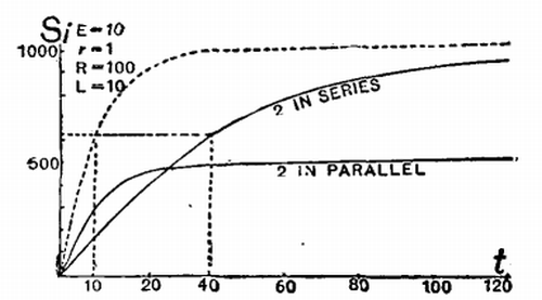
This definite fraction is the fraction (e - 1)/e; or in decimals, 0.634. All curves of rise of current are alike in general shape, they differ only in scale, that is to say, they differ only in the height to which they will ultimately rise, and in the time they will take to attain this fraction of their final value.
Example (1).—Suppose E = 10; R = 200 ohms; L = 8. The final value of the current will be 0.025 amp. or 25 milliamperes. Then the time constant will be 8 ÷ 400 = 1-50th sec.
Example (2).—The P.O. Standard "A" relay has R = 400 ohms; L = 3.25. It works with 0.5 milliampere current, and therefore will work with 5 Daniell cells through a line of 9,600 ohms. Under these circumstances the time constant of the instrument on short circuit is 0.0081 sec.
It will be noted that the time constant of a circuit can be reduced either by diminishing the self-induction or by increasing the resistance. In Fig. 54 the position of the time constant for the top curve is shown by the vertical dotted line at 10 seconds. The current will take 10 seconds to rise to 0.634 of its final value. This retardation of the rise of current is simply due to the presence of coils and electromagnets in the circuit; the current as it grows being retarded because it has to create magnetic fields in these coils, and so sets up opposing electromotive forces that prevent it from growing all at once to its full strength. Many electricians, unacquainted with Helmholtz's law, have been in the habit of accounting for this by saying that there is a lag in the iron of the electromagnet cores. They tell you that an iron core cannot be magnetized suddenly, that it takes time to acquire its magnetism. They think it is one of the properties of iron. But we know that the only true time lag in the magnetization of iron, that which is properly termed "viscous hysteresis," does not amount to any great percentage of the whole amount of magnetization, takes comparatively a long time to show itself, and cannot therefore be the cause of the retardation which we are considering. There are also electricians who will tell you that when magnetization is suddenly evoked in an iron bar, there are induction currents set up in the iron which oppose and delay its magnetization. That they oppose the magnetization is perfectly true, but if you carefully laminate the iron so as to eliminate eddy currents, you will find, strangely enough, that the magnetism rises still more slowly to its final value. For by laminating the iron you have virtually increased the self-inductive action, and increased the time constant of the circuit, so that the currents rise more slowly than before. The lag is not in the iron, but in the magnetizing current, and the current being retarded, the magnetization is of course retarded also.
CONNECTING COILS FOR QUICKEST ACTION.
Now let us apply these most important though rather intricate considerations to the practical problems of the quick working of the electromagnet. Take the case of an electromagnet forming some part of the receiving apparatus of a telegraph system in which it is desired to secure very rapid working. Suppose the two coils that are wound upon the horseshoe core are connected together in series. The coefficient of self-induction for these two is four times as great as that of either separately; coefficients of self-induction being proportional to the square of the number of turns of wire that surround a given core. Now if the two coils instead of being put in series are put in parallel, the coefficient of self-induction will be reduced to the same value as if there were only one coil, because half the line current (which is practically unaltered) will go through each coil. Hence the time constant of the circuit when the coils are in parallel will be a quarter of that which it is when the coils are in series; on the other hand, for a given line current, the final magnetizing power of the two coils in parallel is only half what it would be with the coil in series. The two lower curves in Fig. 54 illustrate this, from which it is at once plain that the magnetizing power for very brief currents is greater when the two coils are put in parallel with one another than when they are joined in series.
Now this circumstance has been known for some time to telegraph engineers. It has been patented several times over. It has formed the theme of scientific papers, which have been read both in France and in England. The explanation generally given of the advantage of uniting the coils in parallel is, I think, fallacious; namely that the "extra currents" (i.e., currents due to self-induction) set up in the two coils are induced in such directions as tend to help one another when the coils are in series, and to neutralize one another when they are in parallel. It is a fallacy, because in neither case do they neutralize one another. Whichever way the current flows to make the magnetism, it is opposed in the coils while the current is rising, and helped in the coils while the current is falling, by the so-called extra currents. If the current is rising in both coils at the same moment, then, whether the coils are in series or in parallel, the effect of self-induction is to retard the rise of the current. The advantage of parallel grouping is simply that it reduces the time constant.
BATTERY GROUPING FOR QUICKEST ACTION.
One may consider the question of grouping the battery cells from the same point of view. How does the need for rapid working, and the question of time constant, affect the best mode of grouping the battery cells? The amateur's rule, which tells you to so arrange your battery that its internal resistance should be equal to the external resistance, gives you a result wholly wrong for rapid working. The supposed best arrangement will not give you (at the expense even of economy) the best result that might be got out of the given number of cells. Let us take an example and calculate it out, and place the results graphically before our eyes in the form of curves. Suppose the line and electromagnet have together a resistance of 6 ohms, and that we have 24 small Daniell cells, each of electromotive force say 1 volt, and of internal resistance 4 ohms. Also let the coefficient of self-induction of the electromagnet and circuit be 6 quadrants. When all the cells are in series, the resistance of the battery will be 96 ohms, the total resistance of the circuit 102 ohms, and the full value of the current 0.235 ampere. When all the cells are in parallel, the resistance of the battery will be 0.133 ohm, the total resistance 6.133 ohms, and the full value of the current 0.162 ampere. According to the amateur rule of grouping cells so that internal resistance equals external, we must arrange the cells in 4 parallels, each having 6 cells in series, so that the internal resistance of the battery will be 6 ohms, total resistance of circuit 12 ohms, full value of current 0.5 ampere. Now the corresponding time constants of the circuit in the three cases (calculated by dividing the coefficient of self-induction by the total resistance) will be respectively—in series, 0.06 sec.; in parallel, 0.5 sec.; grouped for maximum steady current, 0.96 sec. From these data we may now draw the three curves, as in Fig. 55, wherein the abscissæ are the values of time in seconds and the ordinates the current. The faint vertical dotted lines mark the time constants in the three cases. It will be seen that when rapid working is required the magnetizing current will rise, during short intervals of time, more rapidly if all the cells are put in series than it will do if the cells are grouped according to the amateur rule.
FIG. 55.—CURVES OF RISE OF CURRENT WITH DIFFERENT GROUPINGS OF BATTERY.
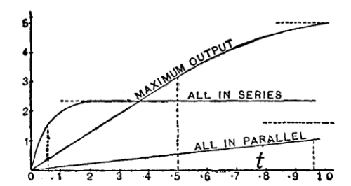
When they are all put in series, so that the battery has a much greater resistance than the rest of the circuit, the current rises much more rapidly, because of the smallness of the time constant, although it never attains the same ultimate maximum as when grouped in the other way. That is to say, if there is self-induction as well as resistance in the circuit, the amateur rule does not tell you the best way of arranging the battery. There is another mode of regarding the matter which is helpful. Self-induction, while the current is growing, acts as if there were a sort of spurious addition to the resistance of the circuit; and while the current is dying away it acts of course in the other way, as if there were a subtraction from the resistance. Therefore you ought to arrange the battery so that the internal resistance is equal to the real resistance of the circuit, plus the spurious resistance during that time. But how much is the spurious resistance during that time? It is a resistance proportional to the time that has elapsed since the current was turned on. So then it comes to a question of the length of time for which you want to work it. What fraction of a second do you require your signal to be given in? What is the rate of the vibrator of your electric bell? Suppose you have settled that point, and that the short time during which the current is required to rise is called t; then the apparent resistance at time t after the current is turned on is given by the formula:
Rt = R × e(R/L)t + ( e(R/L)t - 1 )
TIME CONSTANTS OF ELECTROMAGNETS.
I may here refer to some determinations made by M. Vaschy,4 respecting the coefficients of self-induction of the electromagnets of a number of pieces of telegraphic apparatus. Of these I must only quote one result, which is very significant. It relates to the electromagnet of a Morse receiver of the pattern habitually used on the French telegraph lines.
L, in quadrants.
Bobbins, separately, without iron cores. 0.233 and 0.265
Bobbins, separately, with iron cores. 1.65 and 1.71
Bobbins, with cores joined by yoke, coils in series 6.37
Bobbins, with armature resting on poles. 10.68
It is interesting to note how the perfecting of the magnetic circuit increases the self-induction.
Thanks to the kindness of Mr. Preece, I have been furnished with some most valuable information about the coefficients of self-induction, and the resistance of the standard pattern of relays, and other instruments which are used in the British postal telegraph service, from which data one is able to say exactly what the time constants of those instruments will be on a given circuit, and how long in their case the current will take to rise to any given fraction of its final value. Here let me refer to a very capital paper by Mr. Preece in an old number of the "Journal of the Society of Telegraph Engineers," a paper "On Shunts," in which he treats this question, not as perfectly as it could now be treated with the fuller knowledge we have in 1890 about the coefficients of self-induction, but in a very useful and practical way. He showed most completely that the more perfect the magnetic circuit is—though of course you are getting more magnetism from your current—the more is that current retarded. Mr. Preece'e mode of experiment was extremely simple. He observed the throw of the galvanometer when the circuit which contained the battery and the electromagnet was opened by a key which at the same moment connected the electromagnet wires to the galvanometer. The throw of the galvanometer was assumed to represent the extra current which flowed out. Fig. 56 represents a few of the results of Mr. Preece's paper.
FIG. 56.—ELECTROMAGNETS OF RELAY, AND THEIR EFFECTS.
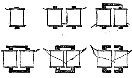
Take from an ordinary relay a coil, with its iron core, half the electromagnet, so to speak, without any yoke or armature. Connect it up as described, and observe the throw given to the galvanometer. The amount of throw obtained from the single coil was taken as unity, and all others were compared with it. If you join up two such coils as they are usually joined, in series, but without any iron yoke across the cores, the throw was 17. Putting the iron yoke across the cores, to constitute a horseshoe form, 496 was the throw; that is to say, the tendency of this electromagnet to retard the current was 496 times as great as that of the simple coil. But when an armature was put over the top, the effect ran up to 2,238. By the mere device of putting the coils in parallel, instead of in series, the 2,238 came down to 502, a little less than the quarter value which would have been expected. Lastly, when the armature and yoke were both of them split in the middle, as is done in fact in all the standard patterns of the British postal telegraph relays, the throw of the galvanometer was brought down from 502 to 26. Relays so constructed will work excessively rapidly. Mr. Preece states that with the old pattern of relay having so much self-induction as to give a galvanometer throw of 1,688, the speed of signaling was only from 50 to 60 words per minute, whereas, with the standard relays constructed on the new plan, the speed of signaling is from 400 to 450 words per minute. It is a very interesting and beautiful result to arrive at from the experimental study of these magnetic circuits.
SHORT CORES versus LONG CORES.
In considering the forms that are best for rapid action, it ought to be mentioned that the effects of hysteresis in retarding changes in the magnetization of iron cores are much more noticeable in the case of nearly closed magnetic circuits than in short pieces. Electromagnets with iron armatures in contact across their poles will retain, after the current has been cut off, a very large part of their magnetism, even if the cores be of the softest of iron. But so soon as the armature is wrenched off, the magnetism disappears. An air gap in a magnetic circuit always tends to hasten demagnetizing. A magnetic circuit composed of a long air path and a short iron path demagnetizes itself much more rapidly than one composed of a short air path and a long iron path. In long pieces of iron the mutual action of the various parts tends to keep in them any magnetization that they may possess; hence they are less readily demagnetized. In short pieces, where these mutual actions are feeble or almost absent, the magnetization is less stable, and disappears almost instantly on the cessation of the magnetizing force. Short bits and small spheres of iron have no magnetic memory. Hence the cause of the commonly received opinion among telegraph engineers that for rapid work electromagnets must have short cores. As we have seen, the only reason for employing long cores is to afford the requisite length for winding the wire which is necessary for carrying the needful circulation of current to force the magnetism across the air gaps. If, for the sake of rapidity of action, length has to be sacrificed, then the coils must be heaped up more thickly on the short cores. The electromagnets in American patterns of telegraphic apparatus usually have shorter cores, and a relatively greater thickness of winding upon them, than those of European patterns.
[1]
Lectures delivered before the Society of Arts, London, 1890. From the Journal of the Society.
[2]
"La Lumiere Electrique," vol. ii.
[3]
"La Lumiere Electrique," vol. iv., p. 129.
[1]
"Bulletin de la Societe Internationale des Electriciens," 1886.