CENTRIFUGAL EXTRACTORS.
Reading edition
By ROBERT F. GIBSON.
Sugar Machines.—Besides separating the crystalline sugar and the sirup, secondary objects are to wash the crystals and to pack them in cakes. The cleansing fluid or "white liquor" is introduced at the center of the basket and is hurled against and passes through the sugar wall left from draining. The basket may be divided into compartments and the liquor guided into each. The compartments are removable boxes and are shaped to give bars or cakes or any form desired of sugar in mass. These boxes being removable cannot fit tightly against the liquor guides, and the liquor is apt to escape. This difficulty is overcome by giving the guides radial movement or by having rubber packing around the edges.
Sugar machines proper are of two kinds—those which are loaded, drained and then unloaded and those which are continuous in their working. The various figures preceding are of the first kind, and what has been said of vibrations applies directly to these.
The general advantages claimed for continuous working over intermittent are—that saving is made of time and motive power incident to introducing charge and developing velocity, in retarding and stopping, and in discharging; that, as the power is brought into the machine continuously, no shifting of belts or ungearing is necessary; and that there are less of the dangers incident to variable motion, either in the machine itself or the belting or gearing. The magma (the mixture of crystalline sugar and sirup) is fed in gradually, by which means it is more likely to assume a position of equilibrium in the basket.
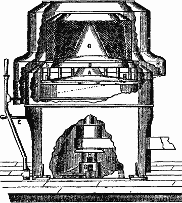
There are two methods of discharging in continuous working—the sugar is thrown out periodically as the basket fills, or continuously. In neither case is the speed slackened. In the first either the upper half of the basket has an upward motion, on the lower half a downward motion (Pat. 252,483); and through the opening thus made the sugar is thrown. Fig. 22 (R.B. Palmer & Sons) is a machine of this kind. The bottom, B, with the cone distributor, a, have downward motion.
Fig. 22.
Continuous discharge of the second kind may be brought about by having a scoop fixed to the curb (or casing), extending down into the basket and delivering the sugar over the side (Pat. 144,319). Another method will be described under "Beet Machines."
Basket.—The construction of the basket is exceedingly important. Hard experience has taught this. When centrifugals were first introduced, users were compelled by law to put them below ground; for they frequently exploded, owing to the speed being suddenly augmented by inequalities in the running of the engine or to the basket being too weak to resist the centrifugal force of the overcharge. Increasing the thickness merely adds to the centrifugal force, and hence to the danger, as even a perfectly balanced basket may sever.
One plan for a better basket was to have more than one wall. For example, there might be an inner wall of perforated copper, then one of wire gauze, and then another of copper with larger perforations. Another plan was to have an internal metallic cloth, bearing against the internally projecting ridges of the corrugations of the basket wall. A further complication is to give this internal gauze cylinder a rotation relative to the basket.
The basket wall has been variously constructed. In one case it consists of wire wound round and round and fastened to uprights, commonly known as the "wire basket;" in another case of a periphery without perforations, but spirally corrugated and having an opening at the bottom for the escape of the extracted liquid; in still another of a series of narrow bars or rings, placed edgewise, packed as close as desired. An advantage of this last style is that it is easily cleaned.
The best basket consists of sheet metal with bored perforations and having bands or flanges sprung on around the outside. The metal is brass, if it is apt to be corroded; if not, sheet iron. The perforations may be round, or horizontally much longer than wide vertically. One method for the manufacture of the basket wall (Pat. 149,553) is to roll down a plate, having round perforations, to the required thickness, causing narrowing and elongation of the holes and at the same time hardening the plate by compacting its texture. Long narrow slots are well adapted to catch sugar crystals, and this is not an unimportant point. Round perforations are usually countersunk. Instead of flanges, wire bands have been used, their lapping ends secured by solder.
As to comparative wear, it maybe remarked that one perforated basket will outlast three wire ones.
As to size, sugar baskets vary from 80 inches in diameter by 14 in. depth to 54 by 24. They are made, however, in England as large as 6 feet in diameter—a size which can be run only at a comparatively slow speed.
A peculiar complication of basket deserves notice (Pat. 275 874). It had been noticed that when a charge of magma was put into a centrifugal in one mass, the sugar wall on the side of the basket was apt to form irregularly, too thick at base and of varied color. To remedy this it was suggested to have within and concentric with the basket a charger with flaring sides, into which the mixture was to be put. When this charger reached a certain rotary velocity, the magma would be hurled out over the edge by centrifugal force and evenly distributed on the wall of the main basket.
Spindle.—The spindle as now made is solid cast steel, and the considerations governing its size, form, material, etc., are identical with those for any spindle. In order that the basket might be replaced by another after draining, the shaft has been made telescopic, but at the expense of stability and rigidity. In Fig. 16 is shown a device to avoid crystallizations, which are apt to occur in large forgings, and would prove fatal should they creep into the upper part of the spindle proper in a hanging machine. It consists of the secondary spindle, c.
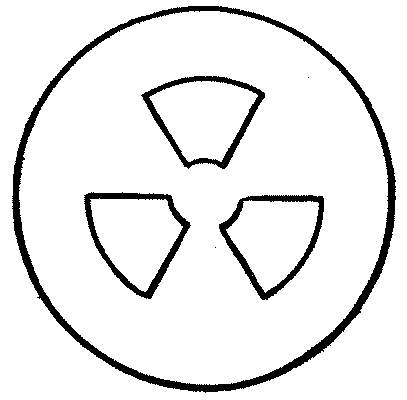
Discharging.—The drained sugar may either be lifted over the top of the basket (in machines which stop to be emptied), or be cast through openings in the bottom provided with valves. A section of the best form of valve may be seen in Figs. 15 and 17. Fig. 23 is a plan of the openings. The valve turns on the basket bearing. It may be constructed to open in the same direction in which the basket turns; so that when the brake is put on, the inertia of the valve operates to open it and while running to keep it closed. There are many other styles, but no other need be mentioned.
Fig. 23.
Casing.—The different styles of casing may be seen by reference to the various drawings. In one machine (not described) the casing is rigidly fixed to the basket, space enough being left between the bottom of the basket and the bottom of the casing to hold all the molasses from a charge. This arrangement merely adds to the bulk of the revolving parts, and no real advantage is gained.
Bearings.—The various styles of bearings can be seen by reference to the figures. One which deserves special attention is shown in Fig. 16 and Fig. 19. In one case it consists of loose disks, in the other of loose washers, rotating on one another. They are alternately of steel and hard bronze (copper and tin).
"There is probably no machine so little understood or so imperfectly constructed by the common manufacturer of sugar supplies as the high speed separator or centrifugal." Unless the product of experience and good workmanship, it is a dangerous thing at high velocities. Besides, its usual fate is to have an incompetent workman assigned to it, who does not use judgment in charging and running. So that designers and manufacturers have been forced not only to take into account the disturbing forces inherent in revolving bodies, but also to make allowance for poor management in running and neglect in cleaning.
Cane and Beet Machines.—The first step in the process of sugar making is the extraction of the juice from the beet or cane. This juice is obtained by pressure. The operation is not usually, but may be, performed in a special kind of centrifugal. One style (Pat. 239,222) consists of a conical basket with a spiral flange within on the shaft, and turning on the shaft, and having a slight rotary motion relative to the basket. The material is fed in and moves downward under increased pressure, the sirup released flying out through the perforations of the basket, the whole revolving at high velocity. The solid portion falls out at the bottom. Another plan suggested (Pat. 343,932) is to let a loose cover of an ordinary cylindrical basket screw itself down into the basket, by reason of its slower velocity (owing to inertia), causing pressure on the charge.
Various other applications of the different styles of sugar machines are the defibration of raw sugar juice, freeing beet crystals of objectionable salts, freeing various crystals of the mother liquor, drying saltpeter.
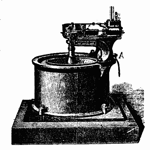
Driers.—Another important division of this first class of centrifugals is that of driers or, as they are variously styled, whizzers, wringers, hydro-extractors. The charge in these is never large in weight compared to a sugar charge, and its initial distribution can be made more symmetrical. The uses of driers are various, such as extracting water from clothes, cloth, silk, yarns, etc. Water may be introduced at the center of the basket from above or below to wash the material before draining. A typical form of drier is shown in Fig. 24. (Pat. Aug. 22, 1876—W.P. Uhlinger.) Baskets have been made removable for use in dyeing establishments, basket and load together going into dyeing vat. Yarn and similar material can be drained by a method analogous to that of hanging it upon sticks in a room and allowing the water to drip off. It is suspended from short sticks, which are held in horizontal layers around the shaft in the basket, and the action is such during the operation as to cause the yarn to stand out in radial lines.
Fig. 24.
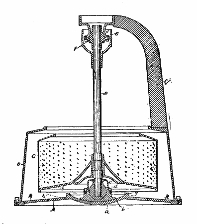
Driers are not materially different from sugar machines. Any of the devices before enumerated for meeting vibrations in the latter may be applied to the former. There is one curious invention which has been applied to driers only (Pat. 322,762—W.H. Tolhurst). See Fig. 25. A convex shaft-supporting step resting on a concave supporting base, with the center of its arc of concavity at the center of the upper universal joint, has been employed, and its movements controlled by springs, but the step was apt to be forced from its support. The drawing shows the improvement on this, which is to give the shaft-supporting step a less radius of curvature.
Fig. 25.
An interesting form of drier has its own motor, a little steam engine, attached to the frame of the machine. See Fig 24. This of course demands fixed bearings. The engine is very small. One size used is 3" × 4". When a higher velocity of basket is required, we have the arrangement in Fig. 26.
Fig. 26.
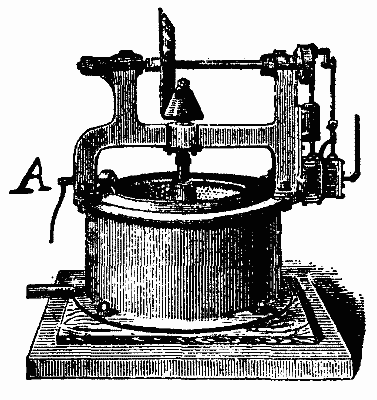
Motors.—This naturally introduces the subject of motive power. We may have the engine direct acting as above, or the power may be brought on by belting. Fig. 27 shows a drier with pulley for belting. Fig. 28 (W.H. Tolhurst) shows a very common arrangement of belting and also the fast and loose pulleys. When the heaviest part of the engine is so far from the vertical shaft as to overhang the casing on one side, there is apt to be an objectionable tremor. To remedy this, it is suggested to put these heavy parts as near the shaft as possible. It has been suggested also to use the Westinghouse type of engine, although the type shown in Fig. 24 works faultlessly in practice.
Fig. 27.
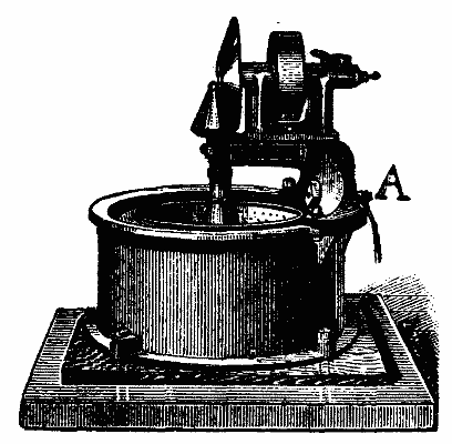
One plan (Pat. 346,030), designed to combine the advantages of a direct acting motor and an oscillating shaft, mounts the whole machine, motor and all, on a rocking frame. The spindle is of course in fixed bearings in the frame. However, the plan is not practical.
Fig. 28.
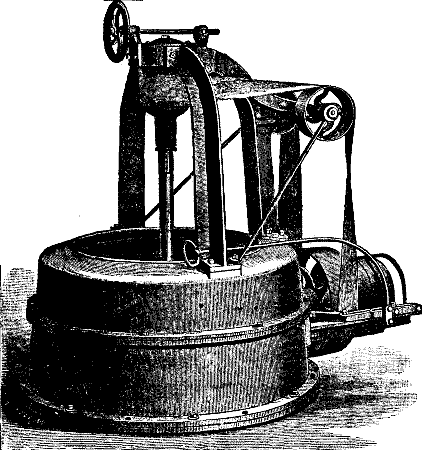
In driers the direct acting engine has many advantages over the belt. The atmosphere is always very moist about a whizzer, and there are frequently injurious fumes. The belt will be alternately dry and wet, stretched and limp, and wears out rapidly and is liable to sever. In all machines in which the shaft oscillates, if the center of oscillation does not lie in the central plane of the belt, the tension of the latter is not uniform. This affects badly both the belt and the running. A reference to the various figures will show the best position for the pulley.
The greatest difficulty experienced with belting is in getting up speed and stopping. The basket must not be started with a sudden impulse. Its inertia will resist and something must give way. A gradual starting can be obtained by the slipping of the belt at first, but this is expensive. The best plan is to conduct the power through a species of friction clutch—an iron disk between two wooden ones. This has been found to work admirably.
Brakes.—The first centrifugals had no brakes. They ran until the friction of the bearings was sufficient to stop them. This occasioned, however, rapid wearing and too great a loss of time. The best material for a brake consists of soft wood into which shoe pegs have been driven, and which is thoroughly saturated with oil. The wooden disks referred to just above are of the same construction. The center of oscillation ought to be in the central plane of the brake as well as that of the pulley, but the preference is given to the pulley.
Figs. 15 and 16 (I) give sectional views of a brake for hanging machines. Figs. 19, 20, and 21 give two sections and a view of a brake which can be used on both hanging and standing machines. A very simple form of brake is shown in Figs. 24, 26, and 27 (A), a mere block pressing on the rim of the basket.
Oil and fat.—A machine in most respects like a whizzer is used for the "extraction of oil and fat and oily and fatty matters from woolen yarns and fabrics, and such other fibrous material or mixtures of materials as are from their nature affected in color or quality when hydrocarbons are used for the purpose of extracting such oily or fatty matters, and are subsequently removed from the material under treatment by the slow process of admitting steam, or using other means of raising the temperature to the respective boiling points of such hydrocarbons, and so driving them off by evaporation." In the centrifugal method carbon-bisulphide, or some other volatile agent, is admitted and is driven through the material by centrifugal force, when the necessary reactions take place, and is allowed to escape in the form of hydrocarbons. A machine differing only in slight particulars from the above is used for cleansing wool.
Loose fiber.—Another application is the drying of loose fiber. Two distinctive points deserve to be noticed in the centrifugal used for this purpose. An endless chain or belt provided with blades moves the material vertically in the basket, and discharges it over the edge. During its upward course the material is subjected to a shower of water to wash it.
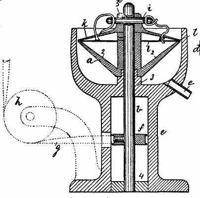
Oil from metal chips.—Very material savings are made in many factories by collecting the metal chips and turnings, coated and mixed with oil, which fall from the various machines, and extracting the oil centrifugally. The separator consists of a chip holder, having an imperforate shell flaring upward and outward from the spindle (in fixed bearings) to which it is attached. When filled, a cover is placed upon it and keyed to the spindle. Between the cover and holder there is a small annular opening through which oil, but not chips, can escape. Fig. 29 (Pat. 225,949—C.F. Roper) is designed (like the greater part of the drawings inserted) to show relative position of parts merely, and not relative size. This style of machine can be used for sugar separating (Pat. 345,994—F.P. Sherman) and many other purposes, to which, however, there are other styles more especially adapted.
Fig. 29.
Filterers.—There are two distinct kinds of centrifugal filterers, working on different principles. Petroleum separators (Pat. 217,063) are of the first kind. They are in form in all respects like a sugar machine. The flakes of paraffine, stearine, etc., which are to be extracted, when chilled are very brittle and would be disintegrated upon being hurled against a plain wire gauze and would escape. Even a woven fabric presents too harsh a surface. It is necessary to have a very elastic basket lining of wool, cotton, or other fibrous material. The basket itself may be either wire or perforated, but must have a perfectly smooth bottom.
As the pressure of the liquor upon the filtering medium per unit of surface depends entirely upon its radial depth, mere tubes, connecting a central inlet with an annular compartment, will serve the purpose quite as well as a whole basket. In this style of machine (Pat. 10,457) the filtering material constitutes a wall between two annular compartments. The outer one is connected with a vacuum apparatus.
Filterers of the second kind work on the following principle: If a cylinder be rapidly revolved in a liquid in which solid particles are suspended, the liquid will be drawn into a like rotation and the heavy particles will be thrown to the outer part of the receptacle. If a perforated cylinder is used as stirrer, the purified liquid will escape into it through the perforations and may be conducted away. The impurities, likewise, after falling down the sides of the receptacle, are carried off. The advantages of this method are that no filtering material is needed and the filtering surface is never in contact with anything but pure liquor.
Very fine sawdust is, to a considerable extent, employed in sugar refineries as a filtering medium. By such use the sawdust becomes mixed with sand, fine particles of cane, etc. As sawdust of such fineness is expensive, it is desirable to purify it in order to reuse it. A centrifugal (Pat. 353,775—J.V.V. Booraem) built on the following principle is used for this purpose. It has been observed that by rotating rather slowly small particles of various substances in water, the finer particles will be thrown outward and deposit near the circumference of the vessel, while the heavier and coarser particles will deposit nearer to or at the center, their centrifugal force not being sufficient to carry them out. A mere rod, extending radially in both directions, serves by its rotation to set the water in motion.
Another form of filter of this second kind (Pat. 148,513) has a rotating imperforate basket into which the impure liquor is run. Within and concentric with it is another cylinder whose walls are of some filtering medium. The liquid already partly purified by centrifugal force passes through into the inner cylinder, thus becoming further purified. Centrifugal filters are used also to cleanse gums for varnishes.
Honey.—The simplest form of honey extractor (Pat. 61,216) consists of a square framework, symmetrical with respect to a vertical spindle. This framework is surrounded by a wire gauze. The combs, after having the heads of the cells cut off, are placed in comb-holders against the wire netting on the four sides, the cells pointing outward. The machine is turned by hand. The honey is hurled against the walls of a receiving case and caught below. But few improvements have been made on this. The latest machines are still hand-driven, as a sufficiently high velocity can be obtained in this manner. In one style the combs are placed upon a floor which rests upon springs. The rotating box is given a slight vertical and horizontal reciprocatory motion, by which the combs are made to grate on the wire gauze sides, breaking the cells and liberating the honey. Thus the labor of cutting the cells is saved. Every comb has two sides, and to present each side in succession to the outside without removing from the basket, several devices have been patented. In some the comb holders are hinged in the corners of the basket, and have an angular motion of ninety degrees. Decreasing the speed is sufficient to swing these. The other side is then emptied by revolving in the opposite direction. In one case each holder has a spindle of its own, connected with the main spindle by gearing and, to present opposite side, turns through 180°. The usual number of sides and hence of comb holders is four, but eight have been used. There are minor differences in details of construction, looking to the most convenient removal and insertion of comb, the reception of the extracted honey in cups, buckets, etc., and the best method of giving rapid rotation, which cannot be touched upon. The product of the operation is white and opaque, but upon heating regains its golden color and transparency.
Starch.—A centrifugal to separate starch from triturated grain, carried in suspension in water, is as follows. (Pat. 273,127—Müller & Decastro.) The starch water is led to the bottom of a basket, and, as starch is heavier than the gluten with which it is mixed, the former will be immediately compacted against the periphery of the basket, lodging first in the lower corner, the starch and gluten forming two distinct strata. A tube with a cutting edge enters the compacted mass so deeply as to peel off the gluten and part of the starch, which is carried through the tube to another compartment of the basket, just above, where the same operation is performed, and so on. There may be only one compartment, the tube carrying the gluten directly out of the machine. These machines are continuous working, and hence some way must be devised to carry the water off. The inner surface of the water is, as we have seen, a cylinder. When the diameter of this cylinder becomes too small, overflow must be allowed. One plan is to have an overflow opening made in the bottom of the basket in such a way that as the starch wall thickens, the opening recedes toward the center. The starch wall is either lifted out in cakes or put again in suspension by spraying water on it and conducting the mixture off.
A centrifugal (Pat. 74,021) to separate liquids from paints depends on building a wall of paint on the sides of the basket and carrying the liquids off at the center.
A centrifugal (Pat. 310,469) for assorting wood pulp, paper pulp, etc., works by massing the constituents in two or three cylindrical strata, and after action severing and removing these separately.
Brewing.—In brewing, centrifugals are quite useful. After the wort has been boiled with hops, albuminous matters are precipitated by the tannic acid, which must be extracted. Besides these the mixture frequently contains husk, fiber, and gluten. The machine (Pat. 315,876), although quite unique in construction, has the same principle of working as a sugar centrifugal, and need not be described. There is one point, however, which might be noticed—that air is introduced at about the same point as the material, and has an oxidizing and refrigerating effect.
Class I. includes also centrifugals for the following purposes: The removal of must from the grape after crushing, making butter, extracting oils from solid fats, separating the liquid and solid parts of sewerage, drying hides, skins, spent tan and the like, drying coils of wire.
Horizontal Centrifugals.—Only vertical machines have been and will be dealt with. Horizontal centrifugals, that is, those whose spindles are horizontal have been made, but the great inconvenience of charging and discharging connected with them has occasioned their disuse; though in other respects for liquids they are quite as good as vertical separators. Their underlying theory is practically the same as that hereinbefore discussed.
Class II., Creamers.—Centrifugals of the second class separate liquids from liquids. There are two main applications in this class—to separate cream from milk and fusel oil from alcoholic liquors. When a liquid is to be separated from a liquid, the receptacle must be imperforate. The components of different specific gravity become arranged in distinct concentric cylindrical strata in the basket, and must be conducted away separately. In creamers the particles of cream must not be broken or subjected to any concussion, as partial churning is caused and the cream will, in consequence, sour more rapidly.
The chief cause of oscillations in machines of this class, where the charge is liquid, is the waves which form on the inner surface. They may be met by allowing a slight overflow over the inner edge of the rim of the basket; or by having either horizontal partitions, or vertical, radial ones, special cases of which will be noticed. Oscillations may also be met in the same manner as in sugar machines, by allowing the revolving parts to revolve about an axis through their common center of gravity. (Pat. 360,342—J. Evans.)
The crudest form of creamer contains a number of bottles, with their necks all directed toward the spindle, filled with milk. The necks, in which the cream collects, are graduated to tell when the operation is complete.
Many methods for introducing the milk into creamers have been devised. It may run in from the top at the center, or emerge from a pipe at the bottom of the basket; or the spindle may be hollow and the milk sucked up through it from a basin below. It is usual to let the milk enter under hydrostatic pressure (Pat. 239,900—D. M. Weston) and let the force of expulsion of the cream be dependent on this pressure. This renders the escape quiet, and prevents churning. Gravity, too, is made effective in carrying the constituents off.
The cream may escape through a passage in the bottom at the center, and the skim milk at the lower outer corner; or by ingeniously managed passages both may escape at or near center. The rate of discharge can be managed by regulating the size of opening of exit passages.
A curious method consists in having discharge pipes provided with valves and floats at their lower ends, dipping into the liquid (Pat. 240,175). "The valves are opened and closed, or partially opened or closed, by the floats attached to them, these floats being so constructed and arranged with reference to their specific gravity and the specific gravity of the component parts of the liquids operated upon, that they will permit only a liquid of a determinate specific gravity to escape through the pipes to which they are respectively attached."
We may have tubes directed into the different strata with cutting edges. (Pat. 288,782.) A remarkable fact noticed in their use is that these edges wear as rapidly as if solids were cut instead of liquids.
The separated fluids may be received into recessed rings, having discharge pipes, the proportionate quantity discharged being regulated by the proximity of the discharge lips to the surface of the ring, and the centrifugal force being availed of to project the liquids through the discharge pipes.
There is a very simple device by which a very rapid circulation of the liquid is brought about. (Pat. 358,587—C.A. Backstrom.) The basket has radial vertical partitions, all but one having communicating holes, alternately in upper and lower corners. The milk is delivered into the basket on one side of this imperforate partition and must travel the whole circuit of the basket through these communicating holes, until it reaches the partition again, and then passes into a discharge pipe. Thus during this long course every particle of cream escapes to the center. As the holes are close to the walls of the basket, the cream has not the undulatory motion of the milk, which would injure it. The greater the number of partitions, the longer is the travel of the milk, and the more rapid the circulation. Blades have been devised similar to the above, having communicating passages extending the whole width of the blade, but we see that here the cream would circulate with the milk; which must not be allowed. Curved blades have been used, and paddles and stirrers, to set the milk in motion, but to them the same objection may be made.
Fig. 30
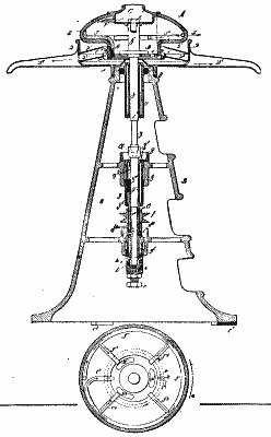
Fig. 30 (Pat. 355,048—C.A. Backstrom) illustrates one of the latest and best styles of creamers. The milk enters at C. The skim milk passes into tube, T, and the cream goes to the center and passes out of the openings in the bottom, kl, k2, and k3, out of the slit, k, and thence out through D5. The skim milk moves through T, becoming more thoroughly separated all the while, and at each of the radial branch tubes, T1, T2, T3, and T4, some cream leaves it and goes to the center, while it passes down out of slit, t3, and thence out of D6.
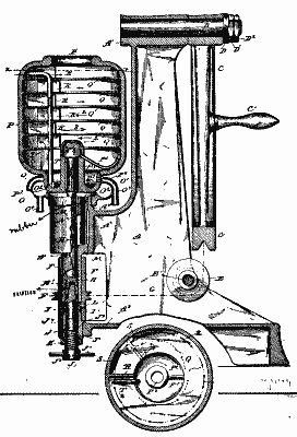
Fig. 31 (Pat. 355,050—C.A. Backstrom) shows another very late style of creamer. A pipe delivers the milk into P4. Passing out of the tube separation takes place, and cream falls down the center to P2 and out of O3. When the compartment under the first shelf becomes full of the skim milk, the latter passes up through the slot, S, strikes a radial partition, R, and its course is reversed. Here more cream separates and passes to center and falls directly, and so on through the whole series of annular compartments, until the top one, when the skim milk enters tube T2 and passes out of O2. By this operation there are substantially repeated subjections of specified quantities of milk to the action of centrifugal force, bringing about a thorough separation. By changing the course of the milk in direction, its path is made longer. This machine can run at much lower speed than many other styles, and yet do the same work.
Fig. 31
Class III., Solids From Solids.—As for grain machines, which are in this class, it may be said that in centrifugal flour bolters, bran cleaners, and middlings purifiers, though theoretically centrifugal force plays an important part in their action, yet practically the real separation is brought about by other agencies: in some by brushes which rub the finer particles through wire netting as they rotate against it.
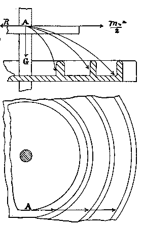
The principle exhibited in a separator of grains and seeds is very neat. (Pat. 167,297.) See Fig. 32. That part of the machine with which we have to do consists essentially of a horizontal revolving disk. The mixed grains are cast on this disk, pass to the edge, and are hurled off at a tangent. Suppose at A. Each particle is immediately acted on by three forces. For all particles of the same size and having the same velocity the resistance of the air may be taken the same, that is, proportional to the area presented. The acceleration of gravity is the same; but the inertia of the heavier grain is greater. The resultant of the two conspiring forces R and (Mv2)/2 varies, and is greater for a heavier grain. Therefore, the paths described in the air will vary, especially in length; and how this is utilized the drawing illustrates.
Fig. 32.
Ore.—In ore machines there is one for pulverizing and separating coal (Pat. 306,544), in which there is a breaker provided with helical blades or paddles, partaking of rapid rotary motion within a stationary cylinder of wire netting. The dust, constituting the valuable part of the product, is hurled out as fast as formed. In this style of machine, beaters are necessary not only for pulverizing, but to get up rotary motion for generating centrifugal force. In the classes preceding, the friction of the basket sufficed for this latter purpose; but here there is no rotating basket and no definite charge. As the material falls through the machine, separation takes place. Various kinds of ore may be treated in the same manner.
An "ore concentrator" (Pat. 254,123), as it is called, consists of a pan having rotary and oscillatory motions. Crushed ore is delivered over the edge in water. The heavy particles of the metal are thrown by centrifugal force against the rim of the pan, overcoming the force of the water, which carries the sand and other impurities in toward the center and away.
Amalgamators.—The best ore centrifugal or separator is what is called an "amalgamator." The last invention (Pat. 355,958, White) consists essentially of a pan, a meridian section of which would give a curve whose normal at any point is in the direction of the resultant of the centrifugal force at that point and gravity. There is a cover to this pan whose convexity almost fits the concavity of the pan, leaving a space of about an inch between. Crushed ore with water is admitted at the center between the cover and the pan, and is driven by centrifugal force through a mass of mercury (which occupies part of this space between the two) and out over the edge of the pan. The particles of metal coming in contact with the mercury amalgamate, and as the speed is regulated so that it is never great enough to hurl the mercury out, nothing but sand, water, etc., escape. There have been many different constructions devised, but this general principle runs through all. By having annular flanges running down from the cover with openings placed alternately, the mixture is compelled to follow a tortuous course, thus giving time for all the gold or other metal to become amalgamated. There are ridges in the pan, too, against which the amalgam lodges. It is claimed for this machine that not a particle of the precious metal is lost, and experiments seem to uphold the claim.
A machine for separating fine from coarse clay for porcelain or for separating the finer quality of plumbago from the coarser for lead pencils uses an imperforate basket, against the wall of which the coarser part banks and catches under the rim. The finer part forms an inner cylindrical stratum, but is allowed to spill over the edge of the rim. The mixture is introduced at the bottom of the basket at the center.
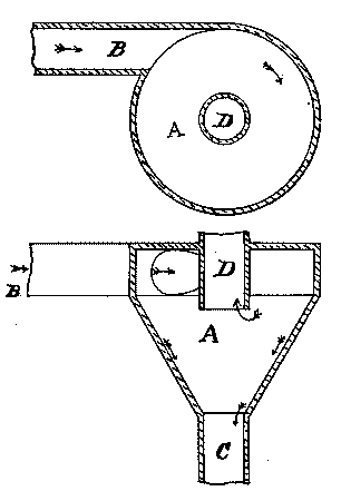
Class IV., Gases And Solids.—There is a very simple contrivance illustrating machines of this class used to free air from dust or other heavy solid impurities which may be in suspension. See Fig. 33. The air enters the passage, B (if it has no considerable velocity of itself, it must be forced in), forms a whirlpool in the conically shaped receptable, A, and passes up out of the passage, D. The heavy particles are thrown on the sides and collect there and fall through opening, C, into some closed receiver.
Fig. 33
Class V., Gases And Liquids.—The occluded gases in steel and other metal castings, if not separated, render the castings more or less porous. This separation is effected by subjecting the molten metal to the action of centrifugal force under exclusion of air, producing not only the most minute division of the particles, but also a vacuum, both favorable conditions for obtaining a dense metal casting.
Most of the devices for drying steam come under this head. Such are those in which the steam with the water in suspension is forced to take a circular path, by which the water is hurled by centrifugal force against the concave side of the passage and passes back to the water in the boiler.
Speed.—The centrifugal force of a revolving particle varies, as we have seen, as the square of the angular velocity, so that the effort has been to obtain as high a number of revolutions per minute as was consistent with safety and with the principle of the machine. For example, creamers which are small and light make 4,000 revolutions per minute, though the latest styles run much more slowly. Driers and sugar machines vary from 600 to 2,000, while on the other hand the necessity of keeping the mercury from hurling off in an amalgamator prevents its turning more rapidly than sixty or eighty times a minute.
However, speed in another sense, the speed with which the operation is performed, is what especially characterizes centrifugal extractors. In this particular a contrast between the old methods and the new is impressive. Under the action of gravity, cream rises to the milk's surface, but compare the hours necessary for this to the almost instantaneous separation in a centrifugal creamer. The sugar manufacturer trusted to gravity to drain the sirup from his crystals, but the operation was long and at best imperfect. An average sugar centrifugal will separate 600 pounds of magma perfectly in three minutes. Gold quartz which formerly could not pay for its mining is now making its owners' fortunes. It is boasted by a Southern company that whereas they were by old methods making twenty-five cents per ton of gold quartz, they now by the use of the latest amalgamator make twenty-five dollars. Centrifugal force, as applied in extractors, has opened up new industries and enlarged old ones, has lowered prices and added to our comforts, and centrifugal extractors may well command, as they do, the admiration of all as wonderful examples of the way in which this busy age economizes time.