SOMZEE'S NEW GAS-BURNERS.
Reading edition
With the object of effecting a very intimate mixture of gas and air, and of causing this mixture to reach the point of ignition at as high a temperature as possible, M. Leon Somzee, of Brussels, has designed several new forms of gas burner, which we now proceed to describe and illustrate, from particulars and by drawings kindly supplied by an esteemed Brussels correspondent.
The high-power burner shown in Fig. 1 effects perfect combustion of the heated mixture of air and gas, which is introduced by the draught determined by the arrangement. What chiefly distinguishes this burner from others of its class is the fact that it is perfectly suited to domestic lighting—that is to say, it may be arranged for a comparatively small consumption of gas, while giving an increase of 250 per cent. of light.
FIG. 1. and FIG. 2. INCANDESCENT AND HIGH-POWER BURNERS.
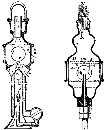
The burner proper is a cage or basket of specially prepared magnesia, which yields a warmer tone of light than any obtained hitherto, while not requiring so high a temperature before combustion. The cap, made of a fire-resisting substance, fits on to a tubular arrangement, R, fixed in the upper portion of the body of the burner. The latter is supplied by air entering at the cone, O, which terminates the inner chamber, K, of the heater, and also by that drawn in by the rising column of gas, passing before the orifices, D, which may be regulated at will. The small burner, I, which is kept constantly alight, heats the central compartment, K, the sides of which transmit heat to the gas circulating in the annular casing, L, of the compartment. The heated gas passes, by the passage, AA¹, into the space, C, where it becomes intimately mixed with the air entering at OP, and also with the outer air arriving by the lateral apertures, D.
The vis viva of the jet is diffused through this mixture, which thus becomes very intimate, when it penetrates into the tubular arrangement, R; combustion now taking place at the top, while the refractory cap emits a bright orange light of great steadiness. As it is not the flow of gas which determines the entrance of the outer air, the former may be used at any pressure—an advantageous arrangement in all respects.
When the small burner, I, in the lower chamber is lighted, the products of combustion issue by the orifice, O, of the compartment, terminating in a needle like that of the steam injector; and the jet draws along the air entering the apertures, PP, above the cone. The gas from the pipe, arriving from the annular space, L, fills the two lateral pockets shown in dotted lines, and passes through the orifices, AA¹, which communicate with the upper chamber of the burner. The manner in which it is conveyed thence to the tubular arrangement has already been described.
Fig. 2 shows a more simple method of carrying out the same principle, and of effecting a considerable saving in gas for a given intensity of light. In this form, a wick, T, impregnated with an alkaline earthy solution, a few seconds after lighting, affords a focus of white light remarkable for its steadiness and brilliancy. A draught of air is created by a jet of gas issuing from the hollow needle, B, and passing through the vessel, D, which is provided with orifices, O, for the entrance of air. The air and gas pass from D into C, whence (after their intimate mixture is effected) they pass into the tubular arrangement, F, at the top of which combustion takes place.
To regulate the proportions in which the air and gas should mingle, in order that the combination should be as intimate as possible, the air inlet is made variable by a perforated collar, which permits of the orifices, O, being more or less covered. The other proportions of the burner—that is to say, the relative capacity of the two compartments and the length of the hollow needle—are determined by the sectional area of the supply-pipe for the gas, which is admitted under moderate pressure. Instead of a wire-gauze cap, impregnated with a solution of metals or of salts, two fine platinum wires may be used—one bent into the form of a semicircle of about an inch radius, and the other (of slightly larger diameter) rolled spirally round the former. When both ends of the two wires are connected with the upper portion of the tubular arrangement (which in this case is flattened), and the gas is ignited at the burner, the metallic arc becomes red hot, and then brightly incandescent, emitting a light, less brilliant indeed than with magnesia, but of remarkable steadiness.
In this case the production of light is chiefly due to the fact that calorific condensation, caused by the use of the helicoidal coil surrounding the curved wire, prevents loss of heat in this conductor. In these forms of high-power burner, in which the gas is used directly for the production of light, the difficulty generally encountered of heating the air (present in a larger volume than the gas) has been successfully overcome.
Fig. 3 shows the straight and outspread flame burner with a special heater. In this arrangement the gas and air are heated before combustion, in the compartment, G, directly exposed to the action of a small Bunsen burner, R, which is placed (in an opaque glass) in the middle of a lyre-shaped figure formed by the two gas-pipes, AA. The burner proper consists of two fine annular passages meeting above, and emitting a thin annular sheet of gas over the guide, T, made of a white refractory substance placed between the two annular jets. The object of this guide is to stretch the incandescent sheet of flame, composed of several jets, and interpose friction, so as to prevent a too rapid ascent of hot gases.
FIG. 3 and FIG. 4 REGENERATIVE BURNERS WITH INVERTED FLAMES.
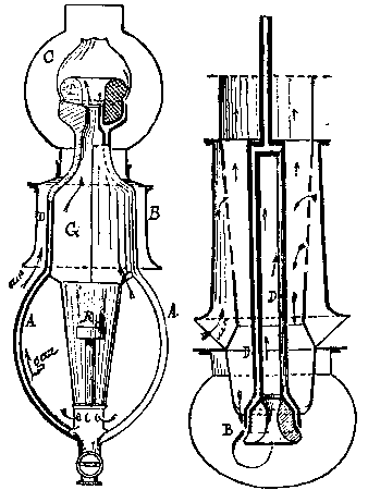
The luminous focus is placed within a glass globe, C, mounted on the bell, B, of the heater; and the external air enters this bell, mingling with the products of combustion of the heating burner, R. The portion, D, of the annular passage, B, being made of a highly conductive metal, the gas becomes heated in passing to the burner, so that both gas and air are raised to the same temperature by the time they reach the orifices of the burner. Instead of prolonging the gas-pipe to the point of bifurcation, a chamber may be arranged immediately below the guide, for the gas and air to become intimately mixed by passing through several perforations or wire gauze, receiving the excess of heat from the white porcelain guide. The admission of gas to both the main and heating burners is regulated by a double valve in the pipe; but this arrangement may be used without any previous heating of the gas and air.
Fig. 4 shows a similar arrangement to that above described, but reversed; the gas and air being previously heated by the products of combustion. The two pipes, D, lead the gas to the burner; and the incandescent sheet of flame is drawn over a white refractory substance, having in its center an orifice through which the hot gases rise to the upper portion of the burner. The luminous sheet is spread out all the better on account of this return of the flames, which also causes the mixture of air and gas to be more complete than when they rise directly. The gas escapes horizontally from the orifices of the annular burner, B, and mingles with the double current of hot air which rushes in above the flame inside the globe, and also below through the central portion of the burner.
This lamp throws its light vertically downward; and its illuminating power may be increased by providing, above the incandescent sheet, a reflector, which diverts into a useful direction the rays thrown toward the ceiling. In this arrangement of lamp the flame is excessively condensed by its being turned back over the refractory guide; and this condensation greatly favors the production of light. On the other hand, the combustion of the gas is very perfect, because the currents of hot air are thrown directly upon the two sides of the flame; and thus the reciprocal action becomes more intense. Lastly, the division of the gas into a large number of small jets, in contact with which the hot air forms an intimate mixture, causes a greater quantity of molecules to partake in the combinations; thus affording a proportionate increase of temperature in a given space and time.
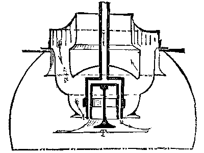
FIG. 5. REGENERATIVE BURNER WITH FLAME DEFLECTED OUTWARD.
Owing to these various circumstances, the final effective duty of this burner is advantageous, so that it yields an illuminating power which may be put at from 200 to 250 per cent. above that of ordinary burners, and about 25 per cent. more than that of other regenerative burners. The flame is comparatively steady; the loss due to the friction over the white porcelain being almost eliminated, because the flame only presses upon the guide for a small portion of its surface, and is only spread out to the extent of its dark zone.
The contact between the incandescent sheet of flame and the guide may be made as short as desired, and the motion of the gaseous mass be directed by a simple button placed in the center of the burner; thus giving the form shown by Fig. 5, which, however, differs from the previous figure in the fact that the inverted flame is directed outward instead of inward.
In this arrangement the button, T, is fixed in the middle of the burner, which is made cylindrical and annular, or may consist of a ring of small tubes, to which the gas is led by a single pipe; leaving the whole "furnace" free for the circulation of air and the products of combustion. This is the most recent development of the principle patented by M. Somzee in 1882, viz., the formation of an illuminating sheet of flame, spread out laterally, while heating the gas and air by the products of combustion.
Figs. 6 and 7 show two forms of burner designed especially to give economical results with a small consumption of gas. The former is an ordinary Argand burner in which hot air is introduced into the upper portion of the flame, so as to increase the activity of combustion. The luminous sheet of flame is then spread out by a metal disk attached to the end of the tube, D, which introduces the air into the flame. The outer air becomes heated in its passage through the wire gauze, T, which absorbs the heat liberated in the interior of the apparatus, and also that which is radiated from the incandescent sheet and reflected by a metal shield, P, surrounding the dark part of the flame.
FIG. 6. and FIG. 7. TYPES OF ECONOMICAL BURNERS.
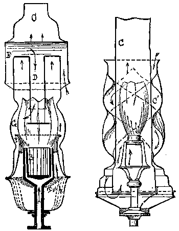
It is the combustion of gas, without the production of useful luminous effect inside the shield, which supplies the reflected as well as radiated heat to the air. The temperature is still further increased by the heat transmitted to the metal portion of the burner, and absorbed by the wire gauze, between the close meshes of which the air from outside is forced to circulate. Air is admitted inside the flame by the chimney, D, placed above the focus, and in which it is raised to a high temperature by friction on the upper part of the lamp glass, at E, and afterward by its passage through the horizontal portion of the bent tube. This tube is impinged upon on the outside by the flames, and also by the products of combustion, so that it forms a veritable heater of the currents which traverse it.
The introduction of hot air into the central portion of the sheet of flame is advantageously supplemented by the spreading out of the flame by means of the metal disk, without any possibility of its being divided. In this way a more intense heat is obtained, and consequently the illuminating power is considerably increased, by the uncombined carbon being more readily set free, and being thus kept longer in the flame, F. This burner, which may be constructed for a moderate gas consumption, gives remarkable results as regards illuminating power and steadiness; the abstraction of heat in no way impairing the luminosity of the flame, which preserves all its brightness.
The Argand burner with double chimney, shown in Fig. 7, is also an economical one for a small consumption of gas. The air admitted to both the inside and the outside is raised to a high temperature by passing along the spirals of a second and transparent chimney, C¹, which surrounds the cylindrical glass, C. The gas itself is heated by passing through this hot chamber before reaching the outlet orifices; so that the mixture of air and gas takes place under the most favorable conditions for their perfect combustion.
The burner is an ordinary Argand, which may terminate below in a small chamber for the gas and air to mingle. But this is not necessary; and the usual arrangement for mixing the air and gas may be adopted. The outer air enters at the top of the central chimney, C and passes into the annular space between the two glasses; then descends by the two spiral passages, which surround the cylindrical glass and terminate in a portion hermetically sealed by a brass plate attached to the supply-pipe. All the parts of the burner are thus surrounded by a highly-heated atmosphere, especially at the bottom of the double chimney; and it will be readily understood that, if the branches which lead the gas to the burner are constructed of a highly conductive metal, the gas will become heated in its turn by passing through passages raised to a high temperature.
The elements are therefore dissociated or separated before their final combination; thereby raising the calorific and luminous effect to the highest possible degree. Such a burner can, of course, be made as small as may be required; thus lending itself admirably to the subdivision of illumination. The only precaution required is to properly proportion the sectional area of the hot-air passages to the radiant surface of the flame, so that the heat does not become too intense at the lower portion of the burner.
Fig. 8 shows a double flame burner on the principle of Mr. Heron's, but with admission of hot air into the angle formed by the flames. As exemplified by Mr. Heron, if two equal batswing burners separately give a certain amount of light, on the two flames being brought into contact, so as to form a single flame, the luminosity is considerably increased, owing to the condensation of heat which results from their meeting. The two incandescent sheets are, as it were, forced into one another, so as to be combined.
FIG. 8. DOUBLE FLAT-FLAME BURNER
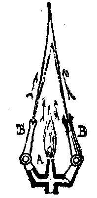
The high-power burners of Douglass, Coze, Mallet, and others were designed on this principle; but its application to uninclosed burners was not very satisfactory, because the great cooling down of the inner surface of the flames by the strong draught of cold air impaired their illuminating power. To counteract this difficulty, M. Somzee adopts a heating burner, A, which he places between the two batswing burners, B, so that the products of combustion rise in the angle made by the two lighting flames, as shown; thus greatly increasing their luminosity while maintaining a low consumption of gas.
M. Somzee also raises the illuminating power of an ordinary flat-flame burner by causing an obscure effluvium to traverse the dark portion of the flame. The effect of this is to increase the activity of decomposition in this portion, so that the particles of carbon are the more readily set free, and remain longer in suspension in the luminous zone. The obscure effluvium may be determined between two points by the electric current, or be caused by the heating of an imperfect conductor by the current; or, again, it may result from a metal conductor heated by the reactions produced in the middle of the flame, by separating the cone of matter in ignition. The effect may be compared with that obtained by the concentration of two sheets of flame; but in this case the sheets are formed by the constituent parts of one and the same flame, whence results a more complete utilization of the elements composing it. This system is, in fact, a simplification of the arrangement adopted in the double-flame burner seen in Fig. 8.
Fig. 9 shows a reflecting and regenerative burner with double glass. The crown, made of metal polished on both sides, has a circular groove, G, for receiving the end of the central chimney, C, and presenting an annular aperture by which the products of combustion enter. The second glass, C¹, is fastened to the collar of the burner carrier, and does not come into contact with the metal crown; so as to allow the air to enter from outside for supplying the burner. The gas enters by the pipe, T, provided with a cock. This pipe is continued to the top of the apparatus, and there spreads out into the form of a dome; thus dividing into two compartments the trunconic chamber, S¹ S², whence the hot gas returns to the body of the burner, B.
FIG 9. REFLECTING AND REGENERATING BURNER.
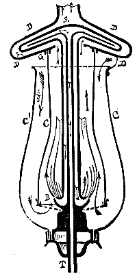
On the burner being lighted from below, the products of combustion rise in the inner chimney, and enter the heater, which they traverse through its entire extent, while impinging against the outside of the gas reservoir, to which they give up a large portion of their heat. They then pass by the passage, D, into the atmosphere or into a chimney. The air necessary for combustion enters at the top of the outer globe, and becomes highly heated in its passage through the space comprised between the two glasses of the burner. In this way it reaches the burner, and forms an intimate mixture with the small jets of gas which compose the flame. The gas, on leaving the supply-pipe, T, fills one of the compartments, S¹ S², of the heater, and then returns by the second compartment, and again descends by the casing of the supply-pipe, having its temperature still further raised by contact with the internal radiation of the flame.
Under these conditions, all the parts of the burner are supplied by heated air, and the combustion becomes very active; thus increasing the intensity of the flame, and consequently that of the light afforded, while at the same time effecting a saving of 50 per cent. of gas. This burner may be made of any size, and for consumptions not exceeding that of an ordinary Argand. In fact, the gas is consumed at a low pressure, escaping with no greater force than that due to the heat of the products of combustion. It is sufficiently expanded on coming into contact with the current of hot air, the activity of which is regulated by the height of the apparatus, that is to say, by that of its two chimneys. The mixture is made in such proportion as to obtain from the gas and air as great a degree of luminosity as possible. The high temperature of the gas, and the independent means of heating the air and gas, constitute the essential principles of this burner.—Journal of Gas Lighting.