SINKING OF THE QUIEVRECHAIN WORKING SHAFT.
Reading edition
The sinking of mine shafts in certain Belgian and French basins, where the coal deposit is covered with thick strata of watery earth, has from all times been considered as the most troublesome and delicate, and often the most difficult operation, of the miner's art. Of the few modern processes that have been employed for this purpose, that of Messrs. Kind and Chaudron has been found most satisfactory, although it leaves much to be desired where it is a question of traversing moving sand. An interesting modification of this well-known process has recently been described by Mr. E. Chavatte, in the Bulletin de la Societe Industrielle du Nord de la France. Two years ago the author had to sink a working shaft at Quievrechain, 111 feet of which was to traverse a mass of moving and flowing sand, inconsistent earth, gravel, and marls, and proceeded as follows:
He first put down two beams, A B (Pl. 1, Figs. 2, 3, and 9), each 82 feet in length and of 20×20 inch section in the center, and upon these placed two others, E F, of 16×16 inch section. Beneath the two first were inserted six joists, c c c c c c, about 82 feet in length and of 14 or 16 inch section in the center. Finally these were strengthened at their extremities with two others, d d, about 82 feet in length. All these timbers, having been connected by tie bands and bolts, constituted a rigid structure that covered a surface of nearly seven hundred square yards.
From the beams, A B and E F, there was suspended a red fir frame by means of thirty-four iron rods.
Upon this frame, which was entirely immersed in the moving sand, there was established brick masonry (Figs. 1, 2, and 3). As the ends of the timbers entered the latter, and were connected by 1½ inch bolts, they concurred in making the entire affair perfectly solid. The frame, K K, was provided with an oaken ring, which was affixed to it with bolts.
After this, a cast iron tubbing, having a cutting edge, and being composed of rings 3.28 feet wide and made of six segments, was lowered. This tubbing was perfectly tight, all the surfaces of the joints having been made even and provided with strips of lead one-tenth of an inch thick. It weighed 4,000 pounds to the running foot.
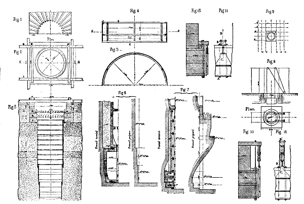
Fig. 1.—Section through A B. Fig. 2.—Plan. Fig. 3.—Section through C D. Fig. 5.—Section through E F of Fig. 4. Figs. 6 and 7.—Work Prepared and finished. Fig. 10.—Section through A B and C D of Fig. 12. Figs. 11 6 and 12.—Arrangement of jack-screw. Fig. 13.—Section through A B and C D of Fig. 11.
Plate I.—SINKING A MINE SHAFT.
It was first raised to a height of fifteen feet, so as to cause it to enter the sand by virtue of its own gravity. It thus penetrated to a depth of about twenty inches. After this the workmen were ordered to man the windlasses and hoist out some of the sand. This caused the tubbing to descend about eight inches more, when it came to a standstill. It was now loaded with 17,000 pounds of pig iron, but in vain, for it refused to budge. Mr. Chavatte therefore had recourse to a dredge with vertical axis, constructed as follows:
Upon a square axis, A B (Pl. 2, Figs. 1, 2, and 3), provided with double cross braces, C D, and strengthened by diagonals, were riveted, by their upper extremities, two cheeks, G H, whose lower extremities held the steel plates, I J I' J', which, in turn, were fastened to the axis, A B, by their other extremities. These plates were so inclined as to scrape the surface of the ground over which they were moved. They each carried two bags made of coarse canvas and strengthened by five strong leather straps (Figs. 2 and 4). To the steel plates were riveted two plates of iron containing numerous apertures, through which passed leather straps designed for fastening thereto the lower part of the mouth of the bags. That portion of the mouth of the latter that was to remain open was fastened in the same way to two other plates, X Y, X¹ Y¹ (Fig. 1), held between the lower cross-braces.
When the apparatus was revolved, the plates scraped the earth to be removed, and descended in measure as the latter entered the bags. These bags, when full, were hooked, by means of the five rings which they carried, to the device shown in Fig. 8 (Pl. 2), and raised to the surface and emptied into cars.
The dredge was set in motion by four oak levers (Figs. 5 and 6). Two of these were manned by workmen stationed upon the surface flooring, and the other two by workmen upon the flooring in the tubbing. The axis was elongated, in measure as the apparatus descended, by rods of the same dimensions fastened together by cast iron sleeves and bolts (Fig. 7).
The steel plates were not capable of acting alone, even in cases where they operated in pure moving sand containing no pebbles, for the sand was too compact to be easily scraped up by the steel, and so it had to be previously divided. For this purpose Mr. Chavatte used rakes which were in form exactly like those of the extirpators, U and V, of Figs. 1, 2, and 3, of Pl. 2, except that the dividers carried teeth that were not so strong as those of the extirpators, and that were set closer together. These rakes were let down and drawn up at will. They were maneuvered as follows:
The dredge descended with the extirpators pointing upward. When their heads reached the level of the upper floor, the tools were removed. Then the dredge was raised again. In this way the extirpators lay upon the floor, and, if the lifting was continued, they placed themselves in their working position, in which they were fixed by the bolts A" B" C" (Fig. 1). After this, the apparatus was let down and revolved. The rakes divided the earth, the scrapers collected it, and the bags pocketed it.
The great difficulty was to cause the tubbing to descend vertically, and also to overcome the enormous lateral pressure exerted upon it by the earth that was being traversed. Water put into the shaft helped somewhat, but the great stress to be exerted had to be effected by means of powerful jack screws. These were placed directly upon the tubbing, and bore against strong beams whose extremities were inserted into the masonry.
As a usual thing it is not easy to use more than four or six such jacks, since the number of beams that can be employed is limited, owing to the danger of obstructing the mouth of the shaft. Yet twelve were used by Mr. Chavatte, and this number might have been doubled had it been necessary. As we have seen, the frame, K K (Pl. 1, Fig. 3), was provided with an oak circle traversed by 32 bolts. The length of these latter was two inches and a quarter longer than they needed to have been, or they were provided with wooden collars of that thickness. Later on, these collars were replaced with iron bars that held the wood against which the jacks bore in order to press the tubbing downward (Pl. 1, Figs. 10, 11, 12, and 13).
Mr. Chavatte's great anxiety was to know whether he should succeed in causing the first section of tubbing to traverse the four feet of gravel; for in case it did not pass, he would be obliged to employ a second section of smaller diameter, thus increasing the expense. He was persuaded that the coarse gravel remaining in the side of the shaft would greatly retard the descent of the tubbing. So he had decided to remove such obstructions at the proper moment through divers or a diving bell. Then an idea occurred to him that dispensed with all that trouble, and allowed him to continue with the first section. This was to place upon the dredge two claw-bars, T (Pl. 2, Fig. 3), which effected the operation of widening with wonderful ease. To do this it was only necessary to turn up the bags, and revolve the apparatus during its descent. The claw at the extremity of the bar pulled out everything within its reach, and thus made an absolutely free passage for the tubbing.
The sands and gravels were passed by means of a single section of tubbing 31 feet in length, which was not stopped until it had penetrated a stratum of white chalk to a depth of two yards. This chalk had no consistency, although it contained thin plates of quite large dimensions. These were cut, as if with a punch, by means of the teeth of the extirpator.
It now remains to say a few words concerning the sinking of the shaft, which, after the operation of the dredge, was continued by the process called "natural level" The work was not easy until a depth of 111 feet had been reached. Up to this point it had been necessary to proceed with great prudence, and retain the shifting earth by means of four iron plate tubes weighing 54 tons. Before finding a means of widening the work already done by the dredge, Mr. Chavatte was certain that he would have to use two sections of tubbing, and so had given the first section a diameter of 16½ feet. He could then greatly reduce the diameter, and bring it to 15¾ feet as soon as the ground auger was used.
After two yards of soil had been removed from beneath the edge of the tubbing, the earth began to give way. Seeing this, Mr. Chavatte let down a tube 13 feet in length and 15.4 in diameter. The exterior of this was provided with 12 oak guides, which sliding over the surface of the tubbing had the effect of causing the tube to descend vertically. And this was necessary, because this tube had to be driven down every time an excavation of half a yard had been made.
Afterward, a diameter of 15.35 feet was proceeded with, and the small central shaft of 4¼ feet diameter was begun. This latter had not as yet been sunk, for fear of causing a fall of the earth.
Next, the earth was excavated to a depth of 8.2 feet, and a tube 16.4 feet in length was inserted; then a further excavation of 8.2 feet was made, and the tube driven home.
After this an excavation of 26¼ feet was made, and a tube of the same length and 14½ feet in diameter was driven down. Finally, the shifting soil was finished with a fourth tube 19½ feet in length and 14 feet in diameter.
A depth of 111 feet had now been reached, and the material encountered was solid white chalk. From this point the work proceeded with a diameter of 13.9 feet to a depth of 450 feet. The small shaft had been sunk directly to a depth of 475 feet. At 450 feet the diameter was diminished by three inches. Then an advance of a foot was made, and the diameter reduced by one and a half inch.
The reason for this reduction in the diameter and change in the mode of deepening was as follows:
The Chaudron moss-box, when it chances to reach its seat intact, and can consequently operate well, undoubtedly makes a good wedging. But how many times does it not happen that it gets injured before reaching its destination? Besides, as it often rests upon earth that has caved in upon its seat during the descent of the tubbing, it gets askew, and later on has to be raised on one side by means of jacks or other apparatus. Under such circumstances, Mr. Chavatte considered this moss-box as more detrimental than useful, and not at all indispensable, and so substituted beton for it, as had previously been done by Mr. Bourg, director of the Bois-du-Luc coal mines.
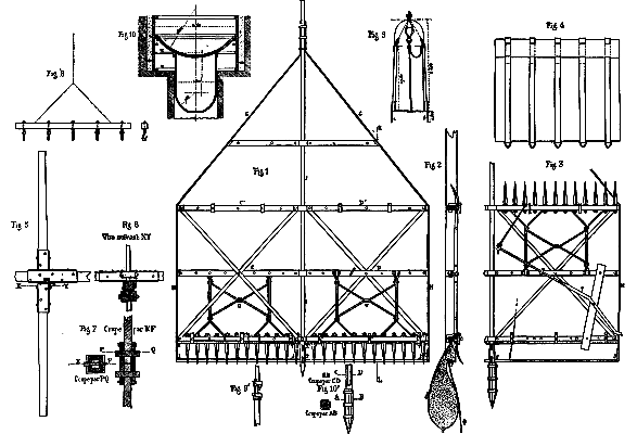
Figs. 1, 2, 3, 6 and 4.—Details of dredge. Figs. 5 6 and 6.—Details of maneuvering lever. Fig. 7.—Mode of lengthening the axis of the dredge. Fig. 8.—Hooks for lifting the dredge bags. Fig. 9.—Arrangement of valves in the beton box. Fig. 10.—Device for centering the tubbing.
Plate II.
This engineer likewise suppressed the balancing column, which is often a source of trouble in the descent of the tubbing, and forced his tubbing to center itself with the shaft through a guide with four branches riveted under the false bottom that entered the small shaft (Pl. 2, Fig. 10). Mr. Bourg so managed that there remained an empty space of ten inches to fill in with beton. Mr. Chavatte had at first intended to proceed in the same way, but the two last tubbings, upon which he had not counted, forced him to reduce the space to 5¾ inches. Under such circumstances it was not prudent to employ the same means for guiding the base of the tubbing, because, if the central shaft had not exactly the same center as the large one, there would have been danger of throwing the tubbing sideways and causing it to leak. Seeing which, Mr. Chavatte strengthened the lower part of the base ring and placed it upon another ring tapering downward, and 27½ inches in height (Pl. 1, Fig. 5). The object of this lower ring was to force the tubbing to remain concentric with the shaft, to form a tight joint with its upper conical portion, and to form a joint upon the seat with its lower flange, so as to prevent the beton from flowing into the small shaft.
After the shaft was pumped out, digging by hand was begun with a diameter of 12 feet. After descending 20 inches an 8×10 inch curb was laid, in order to consolidate the earth and prevent any movement of the tubbing. Then the excavating was continued to a depth of 31½ inches, and with a diameter of 9¾ feet. At this point another curb was put in for consolidating the earth. Finally, the bottom was widened out as shown in Fig. 7, so that three basal wedged curbs could be put in. This done, the false tubbing was put in place; and finally, when proceeding upward, the last ring composed of twelve pieces was reached, the earth was excavated and at once replaced with a collar composed of twelve pieces of oak tightened up by oak wedges. Each of these pieces was cemented separately and in measure as they were assembled.
Through motive of economy no masonry was placed under the base of the three wedged curbs. In fact, by replacing this with a wedged curb of wood traversed by six bolts designed to fix the cast iron curb immediately above, Mr. Chavatte obtained a third curb that he would have had to have made of cast iron.