RAILWAY APPARATUS AT THE PARIS ELECTRICAL EXHIBITION.
Reading edition
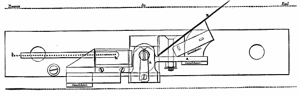
Lartigue's Switch Controller.—The object of this apparatus is to warn the switch tender in case the switch does not entirely respond to the movement of the maneuvering lever.
Fig. 1.—Lartigue's Switch Controller
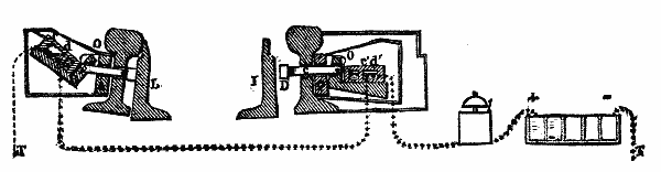
Fig. 2—Transverse Section Fig. 3—Longitudinal Section
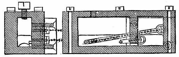
Fig. 4.—Position of the Commutators during the Manuever
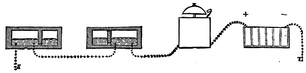
The apparatus, which is represented in the accompanying Figs. 1, 2, 3, and 4, consists of the following parts:
(1.) A mercurial commutator, O, which is fixed on a lever, B, connected with a piece, A, which is applied against the external surface of the web of the main rails, opposite the extremity of the switch plates;
(2.) A bar, C, which traverses the web of the rail and projects on the opposite side, and which carries a nut, D, against which the switch plate abuts;
(3.) An electrical alarm and a pile, located near the switch lever. As long as one of the two plates of the switch is applied against the rail, one of the two commutators is inclined and no current passes. A space of one millimeter is sufficient to bring the commutator to a horizontal position and to cause the electric alarm to ring continuously. If the apparatus gets out of order, it is known at once; for if the alarm does not work during the maneuver of the switch, the tender will be warned that the electric communications are interrupted, and that he must consequently at once make known the position of his switch until the necessary repairs have been made.
Pedals for Transmitting Signals to Crossings.—On railways having a double track and doing a large amount of business it becomes very necessary to announce to the flagmen at railway crossings the approach of trains, so as to give them time to stop all crossing of the tracks. On railway lines provided with electro-semaphores there may be used for this purpose those small apparatus that have been styled semaphore repeaters.
Mr. Lartigue has invented two automatic apparatus, by means of which the train itself signals its approach.
Fig. 5.—Pedal for Sending Warning to Railway Crossing—Elevation.
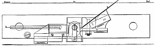
Fig. 6.—Pedal for Sending Warning to Railway Crossing—Plan View.
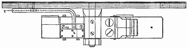
Fig. 7.—End View.
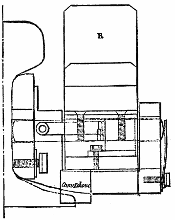
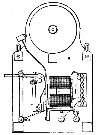
Fig. 8.—Electric Alarm.
1. The first of these, which is generally placed at about 6,000 feet from the point to be covered, consists (Figs. 5, 6, 7, and 8) of a very light pedal fixed to the inside of the rail, and acting upon a mercurial commutator. A spring, R, carried upon the arm, a, of a lever, A, projects slightly above the level of the rail, while the other arm, b, carries a commutator.
The spring, R, on being depressed tilts the box containing the mercury, closes the circuit, and causes an alarm, S, located at the crossing, to immediately ring. In this alarm (Fig. 8) a piece, P, is disconnected by the passage of the current into the electro-magnet, E, which attracts the armature, a, and, a permanent current being set up, the apparatus operates like an ordinary alarm, until the piece, P, is placed by hand in its first position again.
Fig. 9.—Lartigue's Bellows Pedal—Longitundinal Section
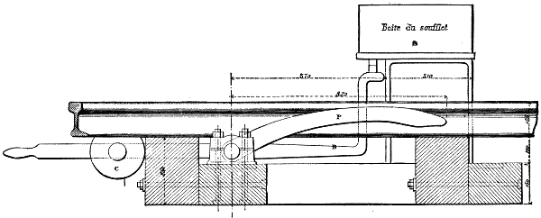
Fig. 10.—General Plan.
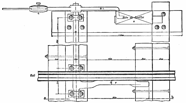
2. The second apparatus, exhibited by the Railway Company of the North, and also the invention of Mr. Lartigue, bears the name of the "Bellows Pedal." It consists (Figs. 9 and 10) of a pedal, properly so called, P, placed along the rail, one of its extremities forming a lever and the other being provided with a counterpoise, C. When a train passes over the pedal, the arm, B, fixed to its axle, on falling closes the circuit of an ordinary electrical alarm, and at the same time the bellows, S, becomes rapidly filled with air, and, after the passage of the train, is emptied again very slowly under the action of the counterpoise. The contact is thus kept up for some few minutes. This apparatus works very satisfactorily, but is cumbersome and relatively high-priced.
Fig. 11.—Brunot's Controller.
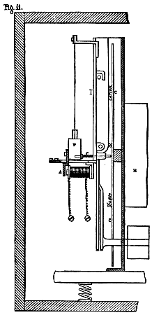
The Brunot Controller as a Controller of the Passage of Trains.—The Brunot Controller, which has been employed for several years on the Railway of the North, is designed to control the regularity of the running of trains, and to make automatically a contradictory verification of the figures on the slips carried by the conductors. In Fig. 11 we give a longitudinal section of the apparatus. It consists of a wooden case containing a clockwork movement, H, upon the axle of which is mounted a cardboard disk, C, divided into hours and minutes, and regulated like a watch, that is to say, making one complete revolution in twelve hours. The metallic pencil, c, which is capable of displacing itself on the cardboard in a horizontal direction opposite a groove on the other side of the disk, traces, when pressure is brought to bear on it, a spiral curve. The transverse travel of the pencil is effected in ninety-six hours. The displacement of the pencil is brought about by means of a cam. Under the influence of the jarring of the train in motion, a weight, P, suspended from a flexible strip, l, strikes against the pencil, c, which traces a series of points. During stoppages there is, of course, an interruption in the tracing of the curve.
Up to this point no electricity is involved—the apparatus is simply a controller of regularity. Mr. Brunot has conceived the idea of utilizing his apparatus for controlling the passage of trains at certain determined points on the line; for example, at the top of heavy grades. For this purpose it has only been necessary to add to the apparatus that we have just described an electro-magnet, E, connected electrically with a fixed contact located on the line. When the current passes, that is to say, at the moment the circuit is closed by the passage of a train, the armature, A, is attracted, and the pencil marks a point on the cardboard disk. This modification of the apparatus has not as yet been practically applied.
Electrical Corresponding Apparatus.—The object of these apparatus is to quickly transmit to a distance a certain number of phrases that have been prepared in advance. The Company of the North employs two kinds of correspondence apparatus—the Guggemos and the annunciator apparatus.
Fig. 12.—Guggemos's Correspondence Apparatus—External View.
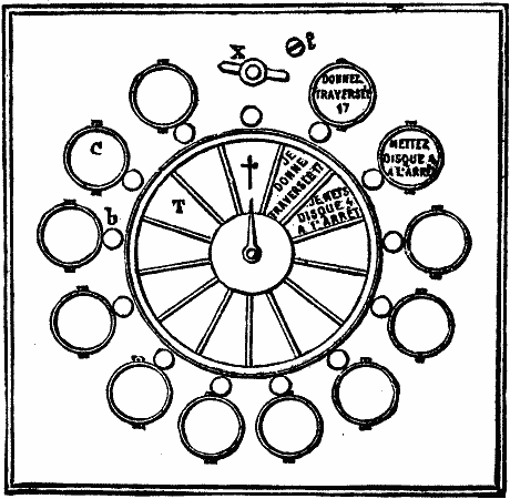
1. The Guggemos Apparatus.—This apparatus serves at once as a manipulator and receiver, and consists of an inner movement surmounted by a dial, over the face of which moves an index hand. Around the circumference of the dial there is arranged a series of circular cases, C, containing the messages to be received, and similar triangular cases, containing the messages to be forwarded, radiating from the center of the dial. Between each of these there is a button, b.
Fig. 13.—Interior of the Same.
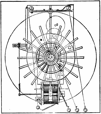
Fig. 13 represents the interior of an apparatus for twenty messages. It consists of a key-board, M, an electro-magnet, B, a clock-work movement, Q, an escapement, s, and an interrupter, F G.
When one of the buttons, b, is pressed, one of the levers of the key-board arrangement touches the disk, M, which is insulated from the other portions of the key-board, and the current then passes from the terminal C to M, and there bifurcating, one portion of it goes to the bobbins of the apparatus and thence to the earth, while the other goes to actuate the correspondence apparatus. The index-hands of the two apparatus thereupon begin their movement simultaneously, and only stop when the pressure is removed from the button and the current is consequently interrupted. H is a ratchet-wheel, which, like the key-board, is insulated from the rest of the apparatus. The button, K, located over each of the dials, serves to bring the index-needles back to their position under the cross shown in Fig. 12. The key, X, serves for winding up the clock-work movement.
Fig. 14.—Annunciator Apparatus.
The Annunciator Apparatus.—This apparatus, which performs the same role as the one just described, is simply an ingenious modification of the annunciator used in hotels, etc.
It consists of a wooden case, containing as many buttons as there are phrases to be exchanged. Over each button, b, there is a circular aperture, behind which drops the disk containing the phrase. Between the buttons and the apertures are rectangular plates, P, in which are inscribed the answers given by pressing on the button of the receiving tablet—a pressure which, at the same time, removes the corresponding disk from the aperture. Two disks located at the upper part carry these inscriptions: "Error, I repeat;" "Wait." The tablets on exhibition have eight disks, and can thus be used for exchanging six different phrases. In the interior, opposite each aperture, there is a Hughes magnet, between the arms of which there oscillates a vertical soft-iron rod, carrying a disk. The maneuver "is simple." By pressing upon a button there is sent into the bobbins of the magnet corresponding to this button a current which causes the disk to appear before one of the apertures, while at the same time an alarm begins to ring. The same maneuver performed by the agent at the receiving-post has the effect of causing the disk to disappear. The two contact springs in communication at each aperture with the alarm and the line are connected by a strip of ebonite, M, against the center of which presses the button.
Electrical Controllers for Water-Tanks.—The object of these apparatus is to warn the person in charge of a water-tank that the latter is full, and that he must stop the engine-pump; or, that the tank is empty, and that he must at once proceed to fill it. The Company of the North has on exhibition two such apparatus—one of them Lartigue's, and the other Vérité's.
Fig. 15.—Controller for Water Tanks (Lartigue System).
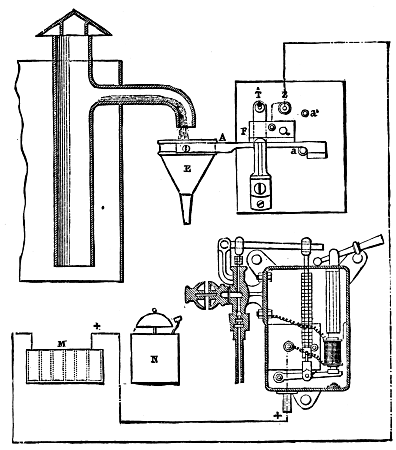
1. The Lartigue Controller (Fig. 15).—This apparatus consists of a long lever, A, which carries at one of its extremities a funnel, E, having a very narrow orifice and which is placed under the overflow pipe of the tank. The lever is kept normally in a horizontal position by a counterpoise; but, as soon as the overflow runs into the funnel, the weight of the water tilts the lever, and the mercurial commutator, F, closes the circuit of a pile, which actuates an alarm-bell located near the pump and engine. The two stops, a and a', limit the play of the lever.
Fig. 16.—Controller for Water Tanks (Vérité System).
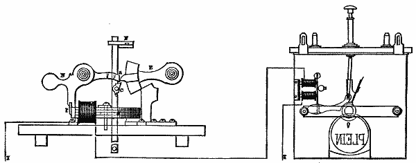
2. The Vérité Controller (Fig. 16).—This apparatus consists of a float, F, provided with a catch, C, calculated in such a way as to act only when the float has reached a certain definite height. At that moment it lifts the extremity of the weighted lever, E, which in falling back acts upon the extremity, a, of another lever, N, pivoted at the point, O. The piece, P, which is normally in contact with the magnet, A, being suddenly detached by this movement of the lever, N, the induced current which is then produced causes the display, near the pump, of a disk, Q, upon which is inscribed the word "Full." This is a signal to stop pumping.