APPARATUS FOR THE MANUFACTURE OF ACETYLENE GAS.
Reading edition
We give herewith, from Le Genie Civil, illustrations and brief descriptions of some of the more prominent apparatus used for the manufacture of acetylene gas.
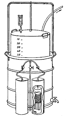
Trouvé Apparatus (Fig. 1).—The principle of the gas generator is that of the hydrogen briquet already applied by Mr. Trouvé in his portable lamp. It consists of two vessels, one entering the other. The internal vessel is provided at the bottom with a discharge pipe communicating, through a cock, with the gasometer. It carries a suspended open work basket containing the carbide of calcium. The bottom of this vessel is provided with an aperture through which it communicates with the external vessel containing the water. The latter is brought to a level in the two vessels and attacks the carbide. The acetylene formed is disengaged and enters the gasometer. At the same time, the excess of pressure forces back the water into the external vessel in suppressing its contact with the carbide. The latter, nevertheless, continues to be attacked slowly through the action of the aqueous vapor. If the cock of the apparatus now be closed, the gas will accumulate in the interior vessel and will soon escape through the aperture in the bottom in raising the column of water. Mr. Trouvé has endeavored to remedy this inconvenience by arranging the pieces of carbide in the basket in distinct layers separated by disks of glass. He has, besides, provided his apparatus with an electric alarm, designed to give warning when the holder is too full or when it is on the point of being empty.
Fig. 1.—TROUVE'S ACETYLENE APPARATUS
Clauzolles Apparatus (Fig. 2).—This apparatus consists of a gas generator, A, hermetically closed and containing the carbide, of a water reservoir, B, communicating with A through a cock, H, and of a gasometer, D, connected with A by the tube and cock, A. The cock, H, is provided with a lever fixed by its extremity to a chain that follows the motions of the holder. When the latter rises or descends, it causes the cock, H, to close or open.
Fig. 2.—CLAUZOLLES' ACETYLENE APPARATUS
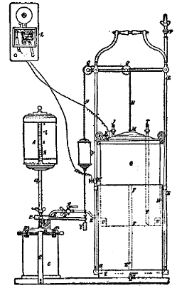
The receptacle, A, is held by a cover fixed by means of four nuts which are removed when it becomes necessary to renew the carbide. The receptacle is removed and replaced by a duplicate one, after the cock, K, has been closed so as to keep the gas in the gasometer.
Bon Apparatus (Figs. 3 and 4).—The acetylene is produced by the reaction of the water falling in small quantity upon the carbide contained in the gas generator, A. The latter is divided into compartments, F, which, filled with carbide, are reached by the water only successively and progressively. When the carbide of the first compartment is exhausted, the water enters the second, and so on. The dimensions and numbers of these departments vary with the size of the apparatus. Each of them contains from ½ lb. to 4.5 lb. of carbide. The box with compartments, F, is covered by a rectangular holder, H, which enters a flat-bottomed receptacle, E, opened above and filled about two-thirds full of water. The latter serves as a hydraulic joint, and, at the same time, as a refrigerator. The holder, H, carries a lead pipe, G', terminating in a funnel into which falls the water from the reservoir, C, led by the pipe, G. This water flows through the extremity, i, of the pipe, G', into the first compartment. Each of the compartments carries, upon the top of the partition that separates it from the following, an aperture through which the water enters the adjoining compartment as soon as the gas in the preceding compartment has made its exit from the gasometer, and so on until the last in the order of the numbers of the compartments.
Figs. 3 and 4.—BON ACETYLENE APPARATUS
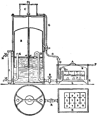
The flow of the water through the pipe, G, is regulated automatically by a cock, r', with counterpoise. The holder, in rising, closes this cock and gradually cuts off the entrance of the water. The gas produced, once consumed, the holder descends in opening the cock, and the water begins to flow again.
The disengaged acetylene enters the gasometer, B, through the pipe, D. The extremity of the latter is bent into the form of a swan's neck. The gas is thus forced to bubble up through about 2 in. of water, in which it is cooled and freed from all traces of the ammonia that it may contain. The cock, R, in the pipe, D, is a three-way one. The first opens and the second intercepts communication between the gas generator and the gasometer, while the third puts these two parts of the apparatus in communication with the atmosphere.
The total capacity of the gasometer is so calculated that the acetylene produced by a single one of the compartments, F, may be stored up therein upon its exit from the gasometer through the pipe, K. The acetylene traverses a purifying column, I, filled with pumice stone saturated with a solution of sulphate of copper and surmounted by a thin layer of carbide of calcium. The object of the sulphate of copper is to free the gas from phosphorus and arseniuret of hydrogen. The layer of carbide serves to dry it.
It is well to use salt water for the gasometer, as acetylene is but slightly soluble therein.
Lequeux-Wiesnegg Apparatus (Figs. 5, 6, and 7).—The apparatus represented in Fig. 5 is capable of being used in lecture courses. It consists of a tank, B, and a holder, A, which is provided at the top with a wide aperture closed by a hydraulic plug, F. When the apparatus is at the bottom of its travel and ready to be filled with acetylene, the plug, F, as well as the basket, D, and the bucket, E, are removed. The quantity of carbide necessary to fill the gasometer is introduced into the basket. After care has been taken to put a certain quantity of water into the gutter forming the hydraulic joint of the plug, F, the parts, E, D, F, are introduced into the tube, C, in operating rapidly enough to prevent the loss of gas. The holder immediately rises as a consequence of the production of acetylene. The gas redescends through a tube to the bottom of the tank and rises laterally in a column by serving as a guide to the holder and as a support to the cocks designed to send the gas to the points of utilization. A cock, H, placed at the lower part of the apparatus, permits of clearing the piping in case a condensation of water occurs.
Figs. 5, 6, and 7.—LEQUEUX-WIESNEGG ACETYLENE APPARATUS
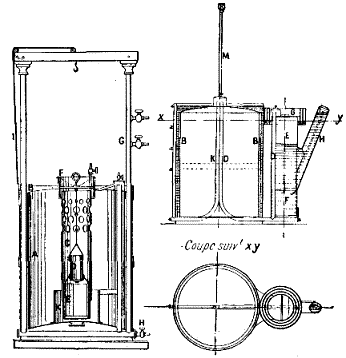
The apparatus represented in Figs. 6 and 7 is continuous. It consists of an apparatus with two holders, that is to say, so arranged as to put the least liquid possible in contact with the gas produced, and to thus prevent absorptions and losses. This gasometer consists of a tank, A, of a movable holder, C, and of a stationary holder, B. The generator, E, is formed of a cylinder, at the bottom of which there is a bucket, F, designed for the reception of the greater part of the lime resulting from the reaction. It is closed by a cover, G, arranged with a simple or multiple joint, according to the precision that it is desired to obtain and that may reach 30 centimeters of water. The figure represents the holder at the bottom of its travel.
Mr. Edward N. Dickerson's Apparatus (Figs. 8 to 13).—Mr. Dickerson, of New York in June, 1895, patented several arrangements permitting of automatically regulating the production of acetylene in measure as it is consumed. In the apparatus represented in Fig. 8 the water is led from a sufficiently high reservoir, A, through the pipe, B, into the gas generator, D, and over the carbide, C, placed upon a grate, O. The acetylene forms when the water reaches the carbide, and its disengagement ceases when the pressure forces the water back. The gas passes through the intermedium of a cock, e, into the pipe, W, provided with a cock, Z, into the automatic regulator, G, and then into the gasometer, P R. Between the regulator, G, and the gasometer, Mr. Dickerson interposes an arrangement consisting of an engine, H, actuating an air pump, K, through the pressure of the gas when it is desired to introduce a mixture of acetylene and air into the gasometer. This arrangement is evidently useless when it is desired to collect the acetylene alone. The gas upon making its exit from the gasometer flows through the pipe, T, to the burners, V.
Fig. 8—DICKERSON ACETYLENE APPARATUS, WITH AUTOMATIC REGULATION.
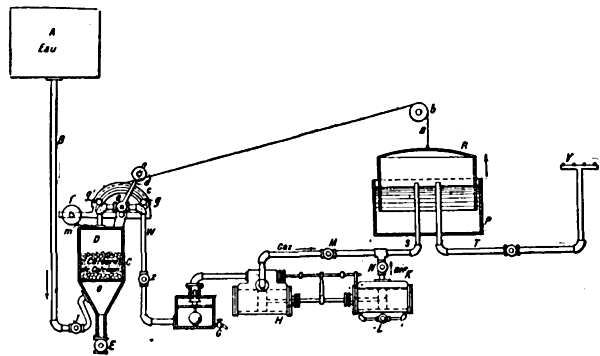
When the holder, R, is filled, the cord or chain, a, passing over the pulley, b, revolves the sector, c, until the pin, g, meets the counterpoised lever, d, of the stopcock, e. In the return of the chain, the other pin, o, carries the lever back to the position shown in the figure.
The gas generator, D, is provided with a discharge cock, E, and a charging aperture, m.
Figs. 9 to 13 show another of Mr. Dickerson's apparatus that permits of an intermittent automatic distribution either of the water upon the carbide or of the carbide in the water in regulating such distribution through the displacement of the holder of a gasometer that collects the excess of gas necessary for the consumption.
Fig. 9.—DICKERSON ACETYLENE APPARATUS, PERMITTING OF THE AUTOMATIC INTERMITTENT DISTRIBUTION OF WATER UPON CARBIDE OF CALCIUM.
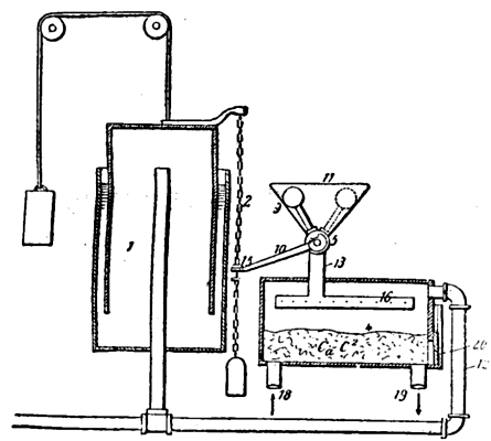
Mr. Dickerson rightly remarks that it is disadvantageous to directly control the distribution of the water upon the carbide by means of the holder of the gasometer. In fact, the water cock may remain open before the holder has moved, and there may thus fall upon the carbide an excess of water, giving rise to a production of acetylene greater than the capacity of the holder warrants.
The object of the Dickerson apparatus is to prevent such overproduction and to furnish water or carbide to the gas generator only as long as the gasometer will have been emptied of the desired quantity of gas.
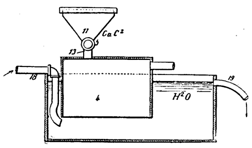
Fig. 10 shows a modification of the gas generator relative to the introduction of the carbide into the water; but the same letters designate the same parts. We shall describe the operations corresponding to the figures.
Fig. 10.—MODIFICATION OF THE GAS GENERATOR OF THE DICKERSON APPARATUS
1 represents the gasometer; 4, the gas generator; 11, the funnel through which the water is introduced into the generator through the pipe, 13; 12, the pipe that connects the generator with the gasometer; 5, a stopcock with counterpoise that alternately opens and closes the communication between the funnel and the generator; 10, a lever connected with the cock, 5; 2, a chain that moves with the holder and maneuvers the lever, 10.
The plug, 6, of the cock, 5, is provided with two conduits, 7 and 8, at right angles. This plug turns 90 degrees, when it is maneuvered by the chain of the gasometer. In the position shown in Fig. 13 the holder is at the top of its travel, and the counterpoise, 9, of the cock is in the position marked by dotted lines in Fig. 9.
Fig. 11, 12, and 13.—DETAILS OF THE DICKERSON ACETYLENE APPARATUS
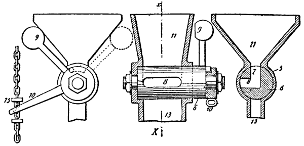
In this case, a charge of water fills the chamber 7 and 8 of the cock. This chamber may be oblong, as shown in Fig. 12, in order to increase its capacity. On the contrary, in the position of the counterpoise, 9, marked in continuous lines in Figs. 9 and 11, the channel, 8, communicates with the pipe, 13; the charge of water of chamber, 7 and 8, has fallen upon the carbides, but another quantity of water has not been able to enter, because the revolution of the cock has cut off all communication between the funnel, 11, and the generator, 4.
The acetylene produced by the reaction of the water upon the carbide raises the gasometer holder, which then actuates the plug, 6, of the cock, 5, and allows a new charge of water to enter the chambers, 7, 8. It is only when the holder descends anew to the position, 1, that the water in the chamber, 7, 8, can fall upon the carbide. The quantity of water that the cock is capable of containing is not sufficient to produce a quantity of gas exceeding the capacity of the gasometer, and, as it is impossible to introduce another quantity of water as long as the gasometer has not been emptied anew, any overproduction of gas is thus rendered impossible.
Fig. 10 applies to the introduction of the carbide into the water. It is necessary in this case that the carbide shall have been previously reduced to powder. The funnel, 11, is then closed by a cover, 21, in order to prevent any accidental escape of the gas. The carbide falls into the generator, the bottom of which is open. The latter enters a tank into which flows a current of water, escaping through the waste pipe, 19, in carrying along the lime formed. The height of the water in the tank is sufficient to furnish the pressure necessary to allow the gas to enter the gasometer through the pipe, 12.