Chapter II
Reading edition
Works of construction: Earthworks, Culverts, Bridges, Foundations, Screw piles, Cylinders, Caissons, Retaining walls, and Tunnels.
Earthworks.—Under this heading may be classified cuttings and embankments of earth, clay, gravel, and rock.
When setting out a line and adjusting the gradients, an endeavour is usually made to so balance the earthworks that the amount obtained from the cuttings may be sufficient to form the embankments. With care, this may be effected to a considerable extent; but there will be places where the material from cutting is unavoidably in excess, and others where the cuttings are too small, or contain good rock, or gravel, which can be more advantageously used for building and ballasting purposes than for ordinary embankment filling. Or there may be a large cutting which will provide enough material to form three or four of the adjoining embankments; but the distance, or lead, as it is termed, to the far embankment may be so long, and, perhaps, on a rising gradient, that it would be cheaper to run the surplus cutting to spoil, and borrow other material for the far embankment from side cutting or elsewhere. A long lead adds materially to the cost and time of forming an embankment, as it not only necessitates a considerable length of service, or temporary permanent way, but also occupies much time in the haulage of the earth waggons. For distances of half a mile and upwards, a small locomotive is more suitable than horses for conveying the waggons.
To run to spoil is the term applied to such of the material from a cutting which, not being required or utilized in the formation of the line embankments, is removed and tipped into mounds, or spoil-banks, in some one or more convenient sites near the mouth of the cutting. Sometimes the surplus material is disposed of by increasing the width of the embankments. Material excavated in a tunnel, and hoisted through the shafts to the upper surface, has to be deposited in spoil-banks along the centre line of the tunnel.
To borrow material to form an embankment is the term used when the earthwork filling is not obtained from the cuttings on the line. This borrowing is generally done by excavating a trench on each side of the line, of such width and depth as will supply sufficient material to form the embankment. Fig. 47 gives an example of an embankment thus made from side cutting. In some cases a piece of high ground adjacent to the embankment can be utilized for obtaining a portion, or even the whole of the filling.
Increased material is sometimes obtained by widening the cutting, or flattening the slopes, or both.
The degree of slope of a railway cutting must be regulated by the nature of the material excavated. A slope of 1½ to 1, which gives for every foot of vertical height a width of one foot 6 inches of horizontal base, as in Fig. 48, is usually adopted for cuttings in ordinary earth, good clay, sand, or gravel. There are some descriptions of strong clay and marl which will stand at a steeper slope, even at 1 to 1; but, on the other hand, there are some kinds of clay which must ultimately be taken out to 2 to 1, and even 3 to 1.
It frequently occurs that the slopes of a clay cutting, taken out to 1½ to 1, appear to stand well for a time, but after exposure to the frost and rain of one or two seasons, the material becomes loosened, and forms into slipping masses, which slide down on to the line, stopping all traffic, and have to be cleared away before train operations can be resumed.
Cuttings through solid rock may be taken out to a slope of ¼ to 1, as shown in Fig. 49, provided the material is compact, and there is not too great a dip in the strata or rock-beds. Where the rock-beds lie at a considerable angle, the slope on the high side will have to be made flatter than the slope required on the low side, as shown in Fig. 50, and great care must be taken to remove from the high side all loose or disconnected pieces of rock which might come away and slide down on to the line.
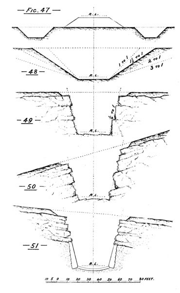
Strong dry chalk will generally stand at a slope of ⅓, or ½ to 1, but when wet and mixed with flints it will be necessary to increase the slope to not less than ¾ to 1. Where the rock is loose and disintegrated, a slope of not less than ½ or ¾ to 1 will be required, and at many points there will be detached threatening masses of rotten rock which must be cleared away to a much flatter slope for safety. In cuttings of this description it is frequently found necessary to clear out a portion of the loose pieces of the lower cavities and build in their place a facework of masonry to support the superincumbent rock. Springs of water rising in the rock, or running over any part of the rock slopes, must be properly provided for, and conducted to the nearest channel. They should be carefully watched during the winter season, when the frost, acting on the water penetrating the crevices, splits and separates large pieces which were previously firm and secure.
Instances will occur where a cutting has to be made through a thick bed of rock and several feet of soft loose strata underneath. The effect of forming a cutting through the soft strata is to induce the heavy bed of rock above to squeeze or force out the softer material below, and unless proper means were taken to avert such a disturbance, the entire cutting would have to be excavated to a very flat slope. The method adopted in such a case is to build strong face-walls of masonry, brickwork, or concrete, underneath the rock, as shown in Fig. 51, with strong inverts placed at short distances. Suitable arrangements must be made to take away the drainage water which will collect at the back of the walls, and weeping-holes or outlets must be left in the lower part of the walls to convey the water into the water-tables on the line.
Where there is a depth of earth cutting on the top of the rock, the earth should be cut away so as to leave a bench or space of 3 or 4 feet between the edge of the rock cutting and the foot of the earth slopes, as shown on Fig. 52.
In cases of shelving rock, with earth or clay on the top, as shown in Fig. 53, it is frequently found necessary to remove the whole of the clay on the high side to prevent the possibility of its sliding off the rock on to the line below.
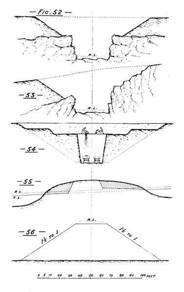
In large cuttings it is usual to push forward a gullet of sufficient width for one or two lines of waggons, as shown in Fig. 54. When this has advanced some distance, strong planks or half balks of timber are placed across the gullet, and the sides or wings of the cutting can be excavated, the material wheeled to the gullet, and tipped from the barrows into the waggons beneath. By this arrangement the work can be carried on very expeditiously, as one set of men can be engaged advancing the gullet and laying the track, while others are following up and taking down the sides. A large number of waggons can thus be filled in a day, and a small locomotive kept fully employed.
Occasions will arise where the material from a large cutting, situate on a continuous gradient, as in Fig. 55, has to be carried in both directions to embankment.
In wet weather, or if the cutting is at all wet, it would be almost, if not quite, impossible to carry on the excavation at the upper end to the proper formation level. The water would collect at the lower level, and not having any means of escape, except by pumping, would stop the work. In such a case the best way is to take out the cutting at the upper end to a slight rising gradient, as shown in the sketch, sufficient to carry away all water, and afterwards take out the lower portion in the working from the other end of the cutting.
Cases will arise where it will be necessary to make a shallow cutting through boggy peaty ground. If the boggy material be very soft, and its thickness from the formation level to the solid ground below be not great, it may be advisable to remove this extra thickness down to the hard lower bed, and fill in up to formation level with strong material. If, however, the bog or peat be too thick to justify its entire removal, it should be excavated say down to two feet below formation level, and a thick layer of branches of trees and strong brushwood closely laid and packed the full width of the road-bed. On this preparatory foundation must be placed good clean ballast to carry the permanent way. Two or three extra sleepers should be allowed to the rail length, and in some instances it will be necessary to introduce two, or even four, rows of strong longitudinal timbers—half balks—under the transverse sleepers. The object of all this extra timber is to obtain a large increase of bearing area on the soft yielding surface of the boggy material. Notwithstanding these special precautions, the trackway will sink down a little during the passage of an engine or train, but will generally return to its former level. Good side drains or water-tables should be formed at each side of the cutting to take away all rain and surface water.
In all cuttings it is desirable to have the line of formation on a slight gradient, sufficient to carry away all rain water or spring water which may be collected in the water-tables; but more particularly so is this necessary in a rock cutting, where the material, being non-absorbent as compared with earth or gravel, requires that all drainage must be carried away to the mouth of the cutting.
In carrying out railway embankments and road approaches, it is usual to form the sides to a slope of 1½ to 1, as shown on Fig. 56. Occasionally the cuttings produce material which might stand at a rather steeper slope, but considering the effects which might afterwards be produced by heavy rains falling on the sides, it is more prudent to adopt the flatter slope of 1½ to 1. Some descriptions of clay will not stand at the above slope, but require a slope of 2 to 1, or even 3 to 1.
When proceeding with the earthworks, it is customary to first remove and lay aside a layer, say 9 inches in depth, of soil and earth from the seat of the embankments and top widths of the cuttings, to be used afterwards in soiling the trimmed and finished slopes of the cuttings and embankments. This soil being removed, the actual work of the excavation can be commenced. The working longitudinal section will give all the necessary particulars as to position of the mouths of the cuttings and the depths at the various chain-pegs, and the top widths of the cuttings can be ascertained by calculation, if on even ground, or from the cross-sections if on side-lying ground, according as the material may be earth, clay, or rock.
For facility of carrying on the works, reliable bench marks, or reduced level stations, must be established at convenient distances along the route of the line, and from these and the fixed chain-pegs the correct line of formation level can be checked from time to time as the work proceeds.
For ordinary earth or clay cuttings, the usual tools are picks and iron crow-bars for loosening, or getting the material, and shovels for filling into barrows, carts, or waggons. For heavy earthworks, steam excavators are now largely employed. Great improvements have been made in this class of machinery, in the way of perfecting the method of excavating lifting, and filling the material into the earth-waggons.
In nearly all rock cuttings the greater portion of the material has to be taken out, or loosened, by blasting with gunpowder, dynamite, or other explosive. The number and extent of the charges will depend upon the nature of the rock and its stratification, and also on its position as regards proximity to buildings or residential property.
Where the rock is loose, or disintegrated, the pieces can generally be readily separated by picks and bars without having to resort to any great extent of blasting.
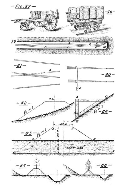
The first of the material excavated in the cuttings is generally conveyed in wheelbarrows to form the commencement of the adjoining embankments. When the wheeling distance becomes too far for economical barrow work, ordinary carts or three-wheeled carts, sometimes termed dobbin carts, are brought into operation where the cuttings and embankments are light; but where the earthwork is heavy, both in excavation and filling, a service or temporary road of light rails and sleepers is usually laid down to carry strong tip earth-waggons. For moderate distances these waggons are hauled by horses, but for distances over three-eighths of a mile a small locomotive is more speedy and economical. Fig. 57 shows one form of dobbin cart; the wheels are made with good broad tyres, so as not to sink too deep into the soft ground, and the body being attached to the framework by a pivot or trunnion on each side, can be readily tilted over, and the earth tipped out, by releasing the holding-down catch. Where the ground is soft and wet, or of a very loose sandy nature, the work of hauling these dobbin carts is very heavy on the horses, and in such cases it soon becomes an advantage to lay down a service road of rails and sleepers. This service road is formed of light rails manufactured for the purpose, or old, worn rails no longer fit for main-line work, spiked down on to rough transverse wooden sleepers. The end of the embankment in course of formation, and where the earth is being tipped, is termed the tip head. Two or more roads are required at the tip head to form the embankment to its full width. Fig. 58 gives a sketch plan of a service road near the tip head. The width is shown as for a double line. The earth-waggons are hauled along the line from the excavation, and brought to a stand at the point A. If a locomotive has drawn the waggons, it is then detached, moved forward, and shunted back into the siding BC. A horse accustomed to tipping then takes one full waggon at a time over one or other of the two turn-outs, DEF or DGH, to the tip head, sufficient impetus being given to the waggon to run the front wheels off the ends of rails on to cross-sleepers laid close, with a steep rise, and backed up with earth. This suddenly checks the frame of the waggon, and the body containing the excavated material revolves on its trunnion, tilts up, and shoots out the material well forward, so that the man in charge of the tip head, who also knocks up the “tail-board catch,” is able to level off the filling without assistance. The empty waggon is then hauled back, and turned into the siding BC, and another full waggon taken forward and tipped, until all the waggons of the rake are emptied. Ten waggons generally form a rake when the work is pushed forward vigorously, each waggon holding about three tons. The tip head horse pulls the waggon by a trace-chain having a spring catch at the end, by which the driver releases the horse at the right moment. It is very important that this spring catch should be kept in good order, because occasionally too much impetus is given to a waggon, which, running over the tip head down the slope, would drag the horse with it if the spring catch did not act properly. Good firm foothold must be provided for the tipping horse.
The tip head should never be carried across culverts or bridges until they have been well backed up, and protected by a thick covering of earth or clay, wheeled in with barrows to an equal height on each side of the masonry, so as to prevent undue side pressure.
Fig. 59 gives a sketch of one form of end-tipping waggon. In some cases the wheels are made of cast-iron, but as these are readily broken during the rough handling to which earth waggons are exposed, it is questionable whether the light wrought-iron wheels, with light steel tyres, used on some works, are not more economical in the long run. The framework and body are made of strong undressed timber, well bound and bolted together. The tail-board catch keeps the body of the waggon in its proper horizontal position while loading or running, but when released leaves the body free to tilt up, and to revolve on the front trunnion by means of the circular clip A. The same principle is also applied to side-tipping waggons which are used for the widening of embankments, or formation of platforms and loading-banks.
The permanent way of these service roads is generally made as simple as possible. A pair of movable rails are used instead of switches, as shown in Fig. 60. These rails are linked together by iron tie-rods, and pulled or pushed over into position for one or other of the roads by means of the handle at A. A stout iron pin, or iron clamping-plate, serves to retain the rails in position during the passing of the waggons. In a similar manner, a short rail working on a pin, or pivot, is made to answer the purpose of an ordinary crossing. The rails are laid complete and continuous for the one road, and for the second road the outer rail is laid sufficiently high to cross over the rail of the first road. A piece of rail is then secured by a centre pin, or pivot, to the cross-sleeper, as shown on Fig. 61. This pivoted rail is pulled over into the position shown by the dotted lines, to allow the passage of waggons on the one road, or pulled across to the end of rail at B, for waggons to pass on or off the other road. In the latter case an iron pin or clamp serves to keep the pivoted rail in position. As these service roads are merely laid down on the soft loose material brought forward for filling, they require constant packing and lifting to prevent them working into depressions, which might cause the waggons to leave the rails.
To indicate the height of the embankment filling, strong stakes or poles must be firmly set in the ground at each chain-peg. On each of these poles two cross-bars must be fixed, the lower one placed to the correct height of the embankment, and the upper one to show the amount allowed for subsidence. The excavated material, as brought from the cuttings, is in a soft, loose condition, and an allowance must be made for its settlement, or subsidence, as the embankment becomes consolidated. This allowance will, of course, depend on the height of the embankment and the quality of the material, but for ordinary earth and clay it is customary to allow about one inch to the foot of height, which is equal to about 8 per cent.
When forming embankments over very side-lying ground, it is necessary to cut steps in the sloping surface on which the filling material has to be placed, as shown in Fig. 62. These steps give a hold to the new earthwork, and check the tendency to slide down the hillside.
Embankments have frequently to be carried over ground which is low, soft, and wet, but not boggy. If the culverts and drains are sufficiently large, and properly arranged, these places are not likely to cause much future trouble.
For a thoroughly soft deep bog, however, it is most difficult to make any accurate calculation as to the amount of embankment filling which will be necessary to form a permanent foundation for the line; and the construction of a high heavy embankment across such a place is one of those undertakings which every engineer is most anxious to avoid. A large quantity of material may be tipped into the bog, and seem to stand fairly well for a time, and then suddenly disappear altogether. More material has to be brought forward, and will most likely disappear in a similar manner. The filling material being heavier than the bog on to which it is thrown, falls through, and displacing the soft semi-liquid matter, continues to sink down lower and lower until it is stopped by a harder stratum underneath. In a measure the operation somewhat resembles the tipping of earth into a lake; the material will go down until it meets with a solid bottom, and in going down it assumes its own natural slope, and forms for itself a width of base corresponding to its height. It will be readily understood what an enormous amount of filling material will be swallowed up in following out such a process. On a very soft bog, say 20 feet in depth, over which an embankment 20 feet high has to be formed, the extent of the actual earthwork filling will very probably closely approach the outline shown in Fig. 63. The upper portion, ABCD, representing the embankment proper, will contain about 133 cube yards to the yard forward, whereas the lower portion, CDEF, which has displaced the soft boggy matter, will contain about 266 cube yards to the yard forward, or, in other words, the filling which is out of sight will be double the filling which is in view above the section ground line.
Apart from the large amount of filling consumed in forming this semi-artificial island, the progress of the work itself is very perplexing. A long length of the bank may have been raised again, once or twice, to the proper height, and may have carried rails and earth-waggons for some weeks, and then sink all at once several feet. The sinking, too, may not be uniform, but may produce fissures, depressions, and separation of the earthwork which will necessitate much care when bringing forward fresh filling material. The bog may not be of the same consistency throughout, there may be some layers of harder material, such as imbedded trunks of trees, and these may sustain the filling for a time, and then yield under the increasing weight of the superincumbent mass. Even when the embankment is finished throughout, and shows no sign of sinking, it should be very carefully watched for a long time for any indication of further movement.
When the bulk of the material has been taken out of an earth or clay cutting, the work of trimming the slopes should be put in hand, so that any surplus left on the wings, or sides, may be removed, and carried away before stopping the earth-waggons. The angle of slope having been decided, a battering rule of light wooden boards is made to correspond to the slope, and in form similar to that shown in Fig. 64. A plumb-bob is suspended from a fixed point, A; the lower end, B, is then held against a peg or mark which indicates the correct level and width of the cutting at the place, and the upper end, C, is raised or lowered until the plumb-bob string coincides with the vertical line marked on the rule from A to D, and the plumb-bob rests steadily in the space cut for it at D. With this battering rule a length of seven or eight feet, according to the size of the rule, is first trimmed to the correct slope, and by continuing the application of the rule up the side, a correct slope line is obtained from bottom to top of slope at that place. By repeating the process at convenient distances along the cutting, a series of correct slope lines are obtained, and the intermediate space can readily be trimmed to correspond.
The same form of battering rule and method of working is applicable for trimming the slopes of the embankments.
When the slopes of the cuttings and embankments have been trimmed, vegetable soil, which has been laid aside, or reserved as previously described, should then be spread evenly over the slopes to the uniform thickness of not less than four inches, and the whole sown with good grass seeds to form a strong sward.
The trimming, soiling, and sowing of the slopes not only gives a more finished appearance to the earthworks, but the strong grass, when once well grown, binds the surface together, and helps to resist the injurious effects of heavy rains and melting snow.
There are many places abroad where a neat finish to the earthworks is considered quite a secondary matter, or where it would be difficult to obtain suitable soil to spread on the slopes. The earthworks are hurried forward to allow the iron highway to be laid down as quickly as possible, the slopes of the cuttings and embankments are only roughly trimmed, and nature is left to supply such grass or vegetation as may spring up, or be self-sown.
The fencing in of a line of railway serves the double purpose of defining the boundary of the company’s property, and of forming a barrier for the prevention of trespass of persons and animals on to the line. For our home lines, fencing is compulsory, and the same obligation exists on many foreign railways. In our colonies, and out in the far West of the United States, and in newly opened out countries, fencing, except near towns and villages, is rather the exception than the rule; people and animals roam at will from one side of the railway to the other wherever they find a convenient crossing place, and the cowcatcher of the engine has to be depended upon for throwing aside any animal which may be standing, or resting, on the line of rails at the passing of a train.
The description of fence will be influenced by the locality, and the materials conveniently obtainable. Where stone is plentiful, perhaps brought forward out of the cuttings, and labour cheap, a masonry wall will be found a most suitable permanent fence. Any fence to be of service should not be less than four feet high. A wooden post and rail fence is much in favour in some districts, the posts being firmly set or driven into the ground, and four or five stout bars nailed on to, or set into, the upright posts. This fencing does not last very long, the pieces are small in size, and soon fail from decay. Quick or hawthorn hedges, when fully grown, make a good fence, but require careful attention to prevent gaps being made by roving cattle. They also require constant trimming and cutting. The quicks are generally planted in a mound formed by cutting a continuous ditch, or gripe, as shown in Fig. 65. The ditch serves as a drain to take away water running down the slopes of the embankments, small openings in the mounds, or drain pipes through them, forming leaders to conduct the water to the ditch or gripe. The outer edge of the ditch represents the boundary of the railway property, unless specially arranged otherwise.
Galvanized iron-steel wire fencing, if not made too light, is strong and durable, and very easily kept in order.
The wires may be secured to strong wooden posts, which should be creosoted, and not placed too far apart, or to iron posts or standards of angle iron or tee-iron section. The straining-posts, whether of iron or timber, must be stronger than the intermediate posts, firmly fixed into the ground, and well stayed, to withstand the pulling and tightening of the wires. There are many places where a quick fence would not grow, and where the ground is too soft to carry a wall. In such cases a good galvanized-wire fencing will fulfil all requirements. The strand wire is better than the plain wire, as its method of manufacture necessitates the use of a superior material, and it is easier to straighten and keep in good order. An extra strong fence is often made of six, eight, or more rows of round rod-iron secured to wrought-iron uprights of bar-iron or tee-iron.
In hot countries abroad an excellent fence is obtained by planting a species of cactus or aloe in a similar manner to the quick fences at home, and as shown in Fig. 66. These cactus plants are readily obtained, are very hardy and quick in growth, and with their large spike-shaped leaves form such an almost impenetrable barrier that few animals will attempt to pass.
Road approaches to bridges over or under the line, or to public road level crossings, may be fenced in the same manner as the line proper. If quicks are adopted, it will be necessary to put up a light wooden fence also to protect the young plants until they are well grown. Near towns and villages it is frequently found advisable to adopt a specially strong wooden fence, or close-boarded fence, where the approach is an embankment, and too newly made to carry a wall.
Gates for farm or occupation level crossings may be made of wood or iron. As a rule, iron gates are preferred, as they can be supplied at the same cost as wood, and are very much more durable. Gates for public road level crossings have to be so placed that they will either close across the railway or across the road; their length will therefore depend upon the width and angle of the road crossing. It is better to make these gates of wood, so that, in the event of a train running through them, there may be less risk of injury to life and rolling-stock than if they were made of iron. For footpath crossings, small gates, wickets, or stiles may be adopted of such form as may be found most suitable for the requirements.
Culverts and Drains.—Before proceeding with the formation of the embankments, it is necessary to construct the culverts and drains which will be covered over by the earthworks. Any existing drains which may be of too light a description must be reconstructed in a more substantial manner. It is a simple and comparatively inexpensive matter to rebuild a drain before the earth filling is brought forward, but it is a costly work to open out an embankment, and rebuild a culvert afterwards. Unless the seat of an embankment is well drained and kept free from the accumulation of running water, the earthwork will be exposed to washing away of the lower layers, and consequent subsidence. Each watercourse or open drain must be provided for either by a separate culvert of suitable size or, as may be done in some cases, by leading two or more watercourses into one, and thus passing all through one culvert of ample capacity. When fixing the sizes of the culverts they must not be limited to the normal flow of water, but a large margin must be allowed sufficient to meet extraordinary floods. The depth of the bed or invert of a culvert is a very important point. If laid too high, and the stream above should at any time deepen, the high invert would check the flow of the water, and would also incur the risk of being undermined and gradually carried away. If, on the other hand, the invert be laid too low, it will gradually silt up to the level of the stream-bed alongside, and there will be so much of the culvert space lost for all practical purposes. In cases when the invert of a culvert has to be laid at a special low depth to allow for future improvements in drainage, it is advisable to give extra height from the invert to the crown, or top, so as to provide ample waterway in the event of any silting up in the mean time. Particular care should be taken when building the foundation of a culvert. It has to be laid on the site of the watercourse, or on a new channel which will ultimately form the watercourse, and it should be built sufficiently deep into the ground to avert as far as possible the chance of water finding a course through below the foundation.
The invert may be of stone pitching or brick if the current is not rapid, or liable to bring down stone boulders from its gravelly bed.
With a stream-course having considerable fall, and which carries with it large stones, roots of trees, and other débris, the invert should consist of strong pitching, composed of large-sized, rough-dressed stones of hard, durable quality, capable of withstanding the pounding of the boulders brought down during floods. A soft description of stone would be quite unsuitable for the invert of such a stream; the pitching would wear away quickly, break, and become detached, leaving the foundation and side walls exposed to the cutting inroads of the water.
Where large flat bedded stones or flags of tough quality can be obtained, they form good covers, or tops, for culverts up to two feet in width. They should have not less than nine inches bearing on the side walls, and their contact edges should be fairly dressed, so as to fit sufficiently close to prevent the embankment filling from falling through.
Where the stream, or run of water, is very small, strong earthenware pipes, 9 inches or 12 inches in diameter, well bedded, may be sufficient to carry away all the water likely to arise. For small springs in low swampy ground, dry stone drains may in many cases be used with advantage. These are made by cutting a trench, say two feet deep by twelve or eighteen inches wide, in the seat of the embankment from side to side, and filling it up with dry rubble stones, not boulders, hand-laid, the upper layer placed on the flat to keep the earthwork as much as possible from filling in between the stones.
In soft boggy ground, where the depth to a hard bottom is very considerable, wooden culverts are frequently adopted. Although these cannot be classed as permanent structures, still, when they are made of sound well-creosoted timber, and substantially put together, they last for a number of years. Sometimes they are made cylindrical in section—a species of elongated cask with strong iron hoops every few feet. Others are rectangular in section, made with two strongly trussed side frames connected and covered with cross-planking and longitudinal tie-planking on the top and bottom.
Wooden culverts are seldom made of very large size, rarely exceeding an opening of 3 feet, and it is considered preferable to use two of these culverts of moderate dimensions than one of large size. Figs. 67 and 68 give sketches of wooden culverts of cylindrical and rectangular section, and Fig. 69 of flag top culverts of 12-inch, 18-inch, and 2-foot openings. In masonry culverts the side walls are shown to be of rubble stonework, but brickwork can be used instead, provided the bricks are well burnt, hard, and capable of withstanding the action of the water.
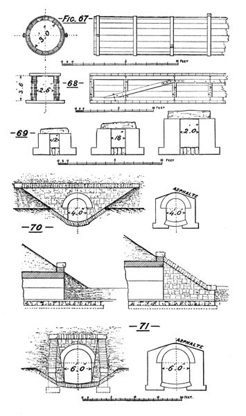
In Figs. 70 and 71 are shown types of arch-top culverts of 4 feet and 6 feet span respectively. The arch portion is shown to be of brick, which, as a rule, is cheaper than stone rings, which must be cut and dressed to suit the small radius of the arch. The side walls may be of brick of good quality. Occasionally they are built of concrete. The wing walls may either be carried out in the direction of the stream, as in the sketch of the 6-foot culvert, or they may be built transverse, as shown on the 4-foot culvert, whichever arrangement is found to work in the best for the case in question.
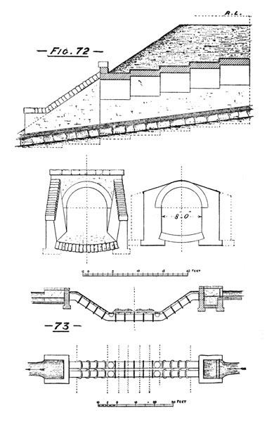
For arch culverts on very steep side-lying ground it is better to build the arch-top in steps, as shown in Fig. 72, instead of forming it parallel to the invert, or slope, of the stream-course. The level portions of the arching give a better hold for the embankment than could be obtained on a long inclined surface of brickwork or masonry.
The writer has built a large number of culverts of this type for mountain streams on steep hillsides, and has found them to prove satisfactory in every way.
In embankments alongside tidal rivers, or across the corners of estuaries of the sea, culverts have frequently to be so constructed that they will permit the passage of the drainage water from the land, or high side, without admitting the tidal water. This can be arranged by placing at the lower end of the culvert close-fitting hinged-flap valves opening outwards. When the tide has gone down the weight of the fresh, or land, water swings the flap-valve sufficiently open to allow of a free passage; and, on the other hand, when the tide rises, the pressure of the water against the face of the flap-valve keeps it tightly closed, and prevents ingress of the salt water.
Culverts are sometimes fitted with lifting-valves or doors, which can be raised or lowered to serve irrigation purposes. The door, which works in guides, is made sufficiently heavy to fall with its own weight, and the raising is effected by means of a screwed suspension-rod working in a well-secured fixed nut.
In cases of soft or treacherous ground, timber-piling or wide bed-courses of cement concrete are necessary to form firm foundations for culverts. Drains and streams which are intersected by a railway cutting have to be dealt with according to their size and their height above the finished rail level. The water from a small drain or field spring may be conducted in pipes down the slope of the cutting into the water-table, or side drain, at formation level, and will be thus carried away to the lower level at the entrance of the cutting. In many cases streams can be diverted, and the water led away to some lower point without the necessity of actually crossing the railway. With a large stream, where it is essential that the water should be conveyed across the line and continue on its ordinary course, it may be carried over in iron pipes or iron trough if there is ample headway, or in iron syphon pipes where the height is not sufficient. The iron pipes or trough can be supported on masonry or brick piers, or cast-iron columns, the height from the rails to the underside of the conduit being not less than that adopted for the over-line bridges.
Occasionally the pipes can be carried across on an over-line bridge, either by placing them under the roadway or on small brackets outside the parapet.
With the syphon arrangement the iron pipes must be laid down the slopes of the cutting and under the road-bed of the permanent way. The pipes must be continuous, strong, and firmly connected at the joints to prevent leakage. The inlet and outlet ends of the pipes should be securely built into receiving-tanks of masonry, brickwork, or concrete, to ensure an uninterrupted flow of the stream, and also to prevent any of the water from percolating through under the pipes and on to the railway. As a precautionary measure, it is well to place iron gratings some little distance in advance of the syphon pipes to intercept and collect any brushwood, straw, or other things which might be brought down with the stream.
Fig. 73 gives an example of the syphon arrangement as constructed with two cast-iron pipes placed side by side.
Railway works carried out in cities and large towns, whether they take the form of cuttings, embankments, arching, or tunnels, are certain to cause a very considerable disturbance of existing drains, corporation sewers, gas-pipes, water-mains and underground telegraph wires. Some of these underground works may be so peculiar and complicated as to necessitate a slight deviation from the course originally intended for the line. Suitable provision will have to be made for each of the items interfered with by the railway, and the substituted work must be carried out to the satisfaction of the constituted authorities within the municipal boundaries.
Bridges.—Amongst the many bridges and viaducts which have to be built during the making of a railway those constructed over rivers and waterways are generally the most important The bridging across any navigable river or tidal water can only be effected in compliance with conditions imposed by the authorities controlling the navigation rights. These conditions will place restrictions as to the number and distance apart of the piers, as well as the height from high water level to the under side of the arches or girders. For rivers having a constant traffic of sea-going vessels of large tonnage and lofty masts the authorities will demand great height or headway as well as large spans; and if to this be added a deep water-way and bad foundations, the work to be constructed becomes one of considerable magnitude. The banks of the river must be carefully studied to find the most favourable point for crossing, and in some cases it may be prudent to make a detour of two or three miles. The crossing at a great height involves the construction of the approach lines at a great height also. If the river is in a deep valley with high sloping sides the natural contour of the ground facilitates the formation of the approach lines; but with a river on a low, wide, open plain, inclined approach lines add enormously to the cost of construction, as well as to the cost of permanent working.
If the number of sailing craft passing up and down the river be moderate, and, perhaps, only passing at high water, the authorities may permit a low-level viaduct with an opening bridge.
There are thus the two systems: the high-level viaduct, which allows trains to pass over and vessels to pass under at any and all times, and the low-level viaduct with opening bridge, which, if open for vessels, is closed for trains, or vice versâ.
Every crossing of a navigable river will have to be considered and dealt with according to its own individual requirements. An arrangement suitable for the one may not be admissible or prudent for the other. A frequent and important train service might be much interfered with by an opening bridge, and, in a similar manner, an opening bridge might cause much interruption and detention to the navigation of the vessels on the river.
Where a low-level viaduct with opening bridge can be adopted, there will be a very great saving of expenditure; and there are numbers of such viaducts in existence, accommodating a large railway and river traffic without inconvenience. Even with a low-level viaduct the height from water-level to the under side of the girders of the various fixed-spans will generally be sufficient for the passage of barges and small craft, leaving the opening portion to be used by the larger vessels.
The principal openings for these large river viaducts are generally constructed for girders, partly on account of the greater facility of girder work for large spans, and also for the advantage of having one uniform height, or headway, from pier to pier.
For a high-level viaduct across a deep-water river, the cost of the lofty piers forms a very important part of the undertaking. Each pier will require its own cofferdam, caisson, or other appliance for obtaining a suitable foundation. The deeper the water, the more costly the arrangement for foundation; and the higher the pier to rail-level, the greater the amount of material in the construction of the pier. The consideration of these two points will at once show that it is very desirable not to have more of these costly piers than is actually necessary, and in studying out the design it will be a question for calculation how far the spans may be increased so as to dispense with one or more piers.
In every work of this description there is a relative proportion between span and height, which will give the most economical result from a cost point of view; the proportion varying according to the depth of the water and description of ground for foundations. An increase in the span will naturally necessitate an increase in the thickness of the pier; but where a cofferdam, or arrangement for putting in the foundations, must in any case be made, a small addition to its width may not necessarily form a large increase to its cost.
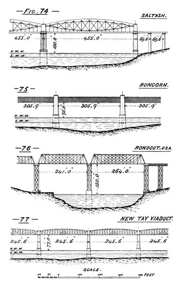
Figs. 74, 75, 76, and 77 are sketches of high-level railway viaducts which have been constructed with great height, or headway, to allow large vessels to pass under at all times without interruption. This description of work is very costly, not only in the deep-water foundations, but also in the heavy scaffolding and appliances requisite for building piers and girders at such an elevation above the ground-level. The hoisting of the material alone forms an important item where such vast number of pieces have to be lifted to a height of 80, 90, or 100 feet.
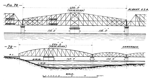
Figs. 78 and 79 are sketches of low-level viaducts constructed with one large opening span, or swing-bridge, for the passage of vessels. The girders and roadway of such opening span are usually constructed as a compact framework, which revolves on a centre placed in the middle of a circular roller path or species of turn-table. The portions of the rotating opening bridge, although not always the same length on each side of the centre-pin, are generally very carefully balanced, to preserve the equilibrium of the entire mass when swinging round for the passage of vessels. To ensure stability in working, and steadiness during heavy gales, a liberal diameter should be given to the roller path of all swing-bridges having large span and great weight.
Lattice, or truss, girders are preferable to plate girders for swing-bridges of considerable opening, as they present less surface area to the action of the wind.
The opening and closing of these bridges is effected by wheel-gearing actuated by hydraulic, manual, or other motive-power. The revolving machinery should be set solid and true, well protected from the weather, and, at the same time, readily accessible for constant inspection, lubrication, or repair.
Figs. 80 to 85 are sketches of various types of railway bridges constructed for smaller openings across narrower rivers, water-ways, or canals. Fig. 80 is an example of what is known as a bascule bridge. This particular bridge is made in two halves, meeting in the centre of the span, the tail end of each half being provided with heavy counterweights to assist in opening or tilting up the bridge for the passage of vessels, or lowering it down for railway traffic. Each half of the bridge swings on horizontal axles, and the raising or lowering is effected by means of hand winches or other motive-power, actuating wheel-gearing working into toothed vertical segments attached to the tail end of each half. The same principle has also been applied to bridges having only one leaf to tilt up to clear the passage way.
Railway bridges of this pattern are now very rarely adopted. They have the great drawback that when raised to the vertical position, a very large area is presented to the action of the wind, and this defect might lead to very serious consequences in the case of a bridge situated in an exposed locality. An open-work floor diminishes the wind area, but a very large surface must necessarily remain.
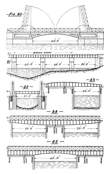
Fig. 81 illustrates what is known as a traversing bridge. In this case the width of the opening passage-way and the adjoining span are made the same, and the girders for the two spans are constructed in one continuous length. By means of gearing attached to the fixed portion of the work, the continuous length of girder, with its roadway, is first slightly raised or lowered, and then drawn back on rollers sufficiently far to leave the opening span quite clear for the passage of vessels. A reverse movement of the gearing causes the movable girders and roadway to travel back and return to their original position ready for the train traffic.
Opening bridges are sometimes constructed on this system in cases where the level of the rails is only a few feet above the level of the water, and where there is only one water opening, and that not more than 20 to 30 feet wide. In such bridges the movable portion is rolled back along iron rails, or plates secured to masonry walls, or strong pile-work. This class of bridge is cumbersome, slow to move, and is now but very rarely adopted.
Fig. 82 shows a type of simple lift bridge, of which there are but few examples remaining. In this particular bridge the girders and roadway form a solid framework, which rests on the abutments during the passage of the trains. Strong chains, secured to the corners of the framework, pass over large sheaves on the top of the iron standards, and then round drums placed below the level of the rails, and terminate by attachment to heavy counter-weights suspended in iron cylinders. The counter-weights are adjusted to approximately balance the bridge, so that a moderate power applied to the wheel-gearing on the drums is sufficient to raise the roadway to the required height. This class of opening bridge is only suitable for the passage of barges and small craft without masts; and it requires the re-adjustment of the counter-weights when the roadway varies in weight, in consequence of rain or repairs.
Figs. 83, 84, and 85 are sketches of small swing-bridges constructed for narrow waterways. Although differing in appearance, they are all practically on the same principle, with centre pin and roller path, and are similar in general arrangement to the large-size-opening swing-bridges shown in Figs. 78 and 79.
The swing-bridge arrangement is so simple in construction, convenient for inspection, and easy to maintain, that where possible it is now generally adopted in preference to any other system. The weights on centre pin and roller path may be distributed as considered most expedient, and by means of suitable appliances the weight may be altogether taken off the centre and rollers when the bridge is closed for the passage of trains.
There are many wide rivers which, although not navigable in the ordinary acceptance of the term, nevertheless require bridges of large spans to provide free waterway for the floating down of rafts of timber. Away in the high ground, in the timber-growing districts, trees are felled, sawn or cut into long poles, logs, or scantlings, and hauled to the banks of the river. The timbers are then formed into large rafts of the most convenient form for floating down to the place of distribution or port for shipment. Even with old experienced floaters, using their long sweeps in the most skilful manner, it is difficult to take anything but a very irregular course down the stream. Under the most favourable circumstances one of these large rafts is an unwieldy, awkward craft to manage; but in a river full of twists and turns, with reaches varying from comparative smooth water to miniature rapids, the current carries the huge mass surging along, and only a clear, unobstructed channel will enable its navigation to be carried out with safety. The presence of a pier in the main waterway might cause destruction to the rafts and loss of life to the men. The vested interests in floating rights are tenaciously guarded, and no new bridge would be sanctioned which would in any way interfere with the waterway or endanger the passage of rafts down the river. Bridges of this description are much less costly than those over deep water—navigable rivers. Excepting the large spans, the rest of the work is comparatively simple. The water is generally shallow, and much reduced in quantity during the summer months. Good foundations can generally be obtained without going to any great depth. The headway may be kept low, or of such height as may best suit the purposes of the railway, and be sufficiently well up out of the way of the floods which may take place from time to time on the river.
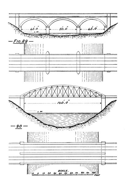
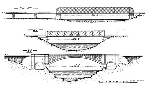
Fig. 86 is a sketch of a bridge constructed over a river much used for rafting purposes. The large span is over the main channel, and the small spans are over a wide gravelly foreshore, which is only covered with water during exceptionally high floods in the autumn or winter. No rafting can be carried on when the river is in flood; the current would be too strong to permit of the raft being kept under control.
Fig. 87 is a sketch of a similar bridge where the river is confined to a regular channel between two sloping banks of strong clay.
Fig. 88 shows a bridge erected over a narrow rocky pass in the river. The channel is hemmed in by the almost perpendicular sides of mountain granite, there are no banks to overflow, the flood waters cannot spread laterally, however much they may increase in depth, and with building-stone at hand in abundance, and foundations formed in the solid rock, the situation is one of the most favourable for a strong permanent bridge. The cast-iron arch of 150-feet span has a graceful appearance, and harmonizes well with the surrounding scenery. A small masonry arch at each end of the bridge provides for communication along the banks of the river.
With rivers which are neither under the control of navigation authorities nor used for rafts of timber, there is much greater freedom for the designing and carrying out of bridges or viaducts suitable for the actual physical conditions of the locality. The headway will be guided only by the height of the railway to be carried across, and by any flood-water levels which may affect the work. The size of the spans will be regulated by the width of the river, the depth of the water, and the nature of the ground into which the piers have to be built. For broad, shallow rivers with good firm river-beds, piers may be built at moderate cost, and comparatively small spans adopted; on the other hand, with a broad deep river it will be better, as previously explained, to reduce the number of piers and increase the span. In the one case, for example, a river 150 feet wide may be crossed with three spans and two piers in the shallow water, as in Fig. 89; in the other it may be more prudent and economical to cross in one span, without any intermediate pier, as shown in Fig. 90.
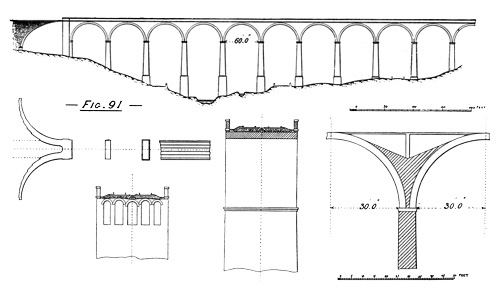
Next in importance to the large bridges and viaducts over rivers are the viaducts which have to be constructed for the crossing of deep inland valleys. The occurrence of one of these deep valleys between long lengths of average table-land renders necessary either a series of cuttings and falling gradients to get down to a low level, or the erection of high-level works to continue onward the rail-level at the height already attained. A decision to adopt the latter course brings forward the consideration as to the method of carrying out the work. To form a high embankment across such a valley would entail an enormous expenditure for earthwork, and several openings, or bridges, would have to be made in the embankment for streams, rivers, and roadways. Instead, therefore, of making this part of the line entirely of embankment, it is usual to carry the earthwork forward until the height is about 25 or 30 feet, and to form the remainder of the opening of arching, as shown in Fig. 91.
This arrangement is not only less costly than an embankment of such height, but has also the great advantage that any or all of the arches are available for the passage of streams, rivers, roads, and accommodation works.
The character of the work to be carried out in the construction of bridges or viaducts over rivers or valleys must greatly depend upon the description of materials at command. Where good building-stone is plentiful, and the price of labour moderate, works of masonry should be adopted as far as practicable. Brickwork is an excellent substitute for masonry, provided that specially selected bricks are used for all facework, or parts exposed to the weather. For water-washed piers and abutments, the lower portion should be faced with good hard stone.
Bridges and viaducts consisting of arches of masonry or brickwork form the most substantial and permanent works of construction for railway purposes; once properly built, the expenditure on future maintenance or repairs is merely nominal. For viaducts the span of the arching must be regulated by the height of the viaduct. The greater the height the larger the span. In one case 30-feet spans may be suitable, whereas in another it may be more economical to introduce spans of 60 feet or more, and so reduce the number of lofty piers. From a cost point of view there is, however, a limit to the span of arching, and, except for special cases, where expenditure is of secondary importance, large spans are very rarely adopted. Arches of large spans, no doubt, have been built both in masonry and brickwork, and have been a complete success in every way except expense. Unfortunately, the quantity and weight of materials in arching, and the corresponding cost, increase very rapidly as the span increases, and for openings of more than 60 or 70 feet girder-work becomes much cheaper than arching.
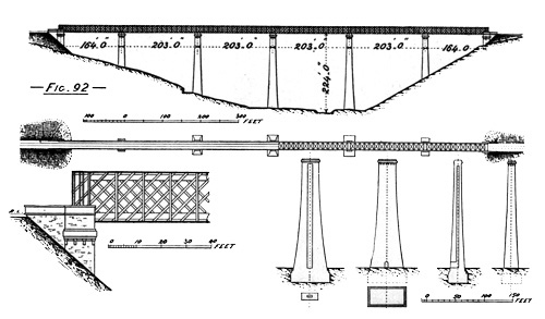
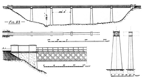
Figs. 92 and 93 are examples of viaducts having piers of masonry, with girders to carry the roadway. In the one case the roadway is carried on the bottom flange of the girders, and in the other on the top. The latter arrangement affords greater facility for securely bracing the girders together, while for the former it is claimed that the girders form a massive parapet, which would serve as a protection in the event of an engine or vehicles leaving the rails.
In the early days of railways, many large viaducts were constructed having masonry piers, and timber trusses to carry the roadway. Much ingenuity was displayed in designing the trusses, and in the introduction of cast-iron joint-shoes and wrought-iron bracings. Many of these wooden superstructures served well for several years, but they were always exposed to the imminent risk of destruction from fire, and however carefully the logs may have been selected, the decay of the timber was only a question of time. The deterioration of one piece was equivalent to the weakening of the entire truss, and the renewal of any part was both difficult and costly. The shrinkage of the timber, and the working at the joints, caused the trusses to deflect considerably under a passing load, and although the actual strength of the structure may not have been much impaired, the creaking and depression had anything but a reassuring effect. Timber superstructures for anything but small spans are rarely adopted now, except for temporary works, or on lines abroad, where the transport on girder-work would be very costly, and where good timber is very cheap and abundant. Even in the latter case the wooden superstructure is generally looked upon as a temporary expedient, to be replaced at no very remote date with iron or steel girders, when the materials can be conveyed over the entire completed line.
Figs. 94, 95, and 96 are sketches of three types of timber trusses as constructed in viaducts of several spans.
There are many localities, especially abroad, where suitable stone is most difficult to obtain, and very expensive to work and convey. In such cases it is compulsory to use as little of it as possible, and to resort to iron or steel both for the girders and a large portion of the piers. The piers may be made of cast-iron, wrought-iron, or steel, of suitable form and arrangement to ensure strength and stability. Not only must the piers be strong enough to carry the weight that may be brought upon them vertically, but they must have sufficient width of base to ensure lateral steadiness. The design should admit of facility of erection, with a minimum of scaffolding, and the pieces should be of convenient length and weight for transport. The lower length of river piers, or portion liable to be in contact with flood-water, should be of solid masonry, to resist the action of the water, or of any débris brought down by the current. More than one fine viaduct has been swept away for want of due attention to the latter precaution.
Fig. 97 illustrates a type of pier composed of cast-iron columns, well braced and stayed with wrought-iron. The ends of the columns and all contact surfaces should be properly turned and faced by machinery to ensure true and perfect joints, and the socketed ends should be turned and bored to fit closely. The latter is important, and if not carefully carried out, a slight sliding movement of the flanges may take place, and throw undue strain on the bolts.
Fig. 98 shows a very similar pier, constructed entirely of wrought-iron or steel.
Each of the above-described piers has a liberal amount of taper or batter, both in the front and transverse elevation.
The size and number of the columns, and the dimensions of the braces or stays, will depend upon the height of the pier and the weights and strains to be sustained.
Many important and lofty viaducts have been erected on this principle of iron piers springing from masonry foundations, more particularly across deep rugged ravines abroad, where iron piers offered the only practical, substantial means of dealing with what appeared otherwise an impossibility.
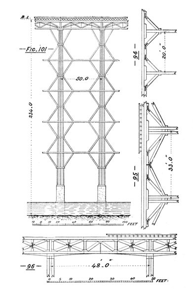
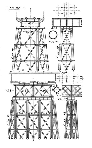
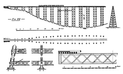
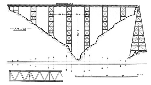
Fig. 99 is a sketch of the Kinsua Viaduct on the Erie Railway, one of the highest railway viaducts in the United States. In the transverse elevation the piers have a large amount of taper; but in the front elevation they are vertical, and of width to correspond to one of the small spans of the main girder. This arrangement of long and wide base gives great stability to the pier. The spans of the girders, which are of the ordinary lattice type, are not large, being 61 feet for the clear spans, and 38 feet 6 inches for those over the piers. The principal interest is in the great height and simplicity of the piers. The rail-level over the top of the pier is 301 feet above the level of the water in the Kinsua stream. The width of this pier on the top is 10 feet (for single line), and the width at the bottom 103 feet.
Fig. 100 is a sketch of the Loa Viaduct on the Antofagasta Railway, Bolivia, stated to be the highest railway viaduct in the world. The arrangement of spans and piers is very similar to the Kinsua Viaduct. The main spans are 80 feet, and the pier spans 32 feet. The width of the pier on the top is 10 feet 6 inches (for single line), and the width at the bottom of the highest pier is 106 feet 8 inches.
In contrasting these light iron piers with what would have been required if constructed of masonry, an idea may be formed of the enormous amount of material, labour, and time, which would have been expended to erect the work in stone.
Before the principle of lofty iron piers had been thoroughly developed, many high piers had been built of timber both at home and abroad. More particularly was this the case in the United States of America, where the presence of magnificent timber close to hand offered special inducements for the use of wood. Like a mammoth scaffolding, each pier was constructed with a most liberal supply of material, judiciously selected and carefully put together, but the danger of destruction by fire was ever present from the beginning. Probably more timber piers and bridges have been destroyed by fire than have been removed on account of natural decay.
One of the most notable of these timber-pier constructions was that of the Old Portage Viaduct, on the Erie Railway, U.S.A. Fig. 101 is a sketch of one or two of the piers. This viaduct was more than 800 feet long, and 234 feet high from the bed of the river to the rail-level. The spans were 50 feet each. Masonry piers were carried up to about 25 feet above the ordinary water-level of the river, and upon these the timber superstructure was erected. Each timber pier consisted of three complete sets of framework, securely connected together, and also well stayed and braced to the adjoining piers. This viaduct was destroyed by fire in 1875, and was reconstructed with piers and girders of iron.
Railway bridges over or under public roads of primary or secondary importance must be constructed to the widths and heights prescribed for such works in the fixed regulations of the country in which they have to be built. As a rule, these road-bridges are simple and inexpensive in character, except in towns, or in cases where the line crosses the roads very obliquely, or where the road is situated at the top of a deep cutting, or bottom of a high embankment. Away from towns and out in the open country, permission is generally obtained to divert the roads to a moderate extent, so as to obtain a more favourable angle and height for the bridge; but in towns, where the roads become streets, sometimes of great width, with houses and shops on each side, little or no diversion can be allowed.
A railway passing through a portion of a densely populated town must deal with the streets as they exist, as any great alteration in their course or continuity would involve a large destruction of property. With careful laying out it is possible to obtain favourable crossings for many of the streets, but a number of others must be crossed obliquely, and these oblique crossings very frequently result in a span twice the width, or even more, of what would be necessary to cross the street on the square. Bridge-work in towns is more costly than in the country, as a higher class of work is demanded, more finish or dressed work in the masonry or brickwork, and more ornamentation in the screens and parapets in connection with the iron girder-work. The work itself has to be carried on in a confined locality, with limited space for materials and appliances, and where the thoroughfare must be kept open.
Where the height is sufficient, and suitable materials readily obtained, it is preferable to adopt an arch bridge, as being of a much more permanent character than girders.
Fig. 102 is an example of an ordinary over-line arch bridge to carry a public road over a double line of railway in a cutting of moderate depth.
Fig. 103 shows a somewhat similar over-line arch bridge, but its height from rail to road-level being greater, side arches are introduced in preference to long heavy wing walls.
Fig. 104 shows an over-line arch bridge in a rock cutting. In this case, by increasing the span and forming the springing bed in the solid rock, the masonry of abutments and wing walls may be reduced to a minimum.
Fig. 105 is a sketch of an ordinary under-line arch bridge to carry a railway over a public road in an embankment of moderate height.
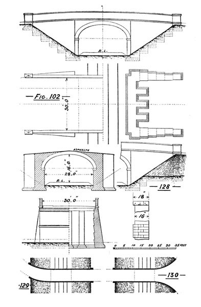
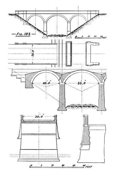
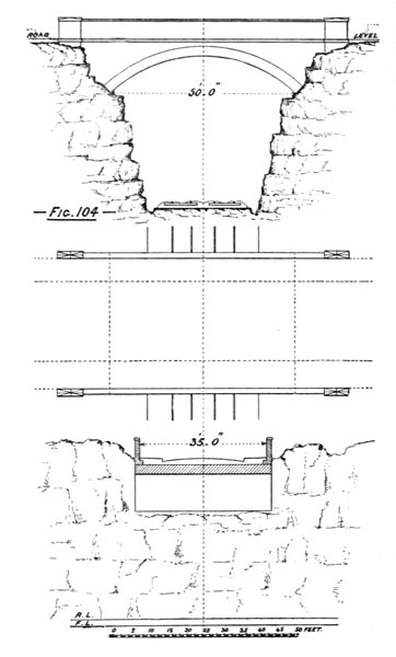
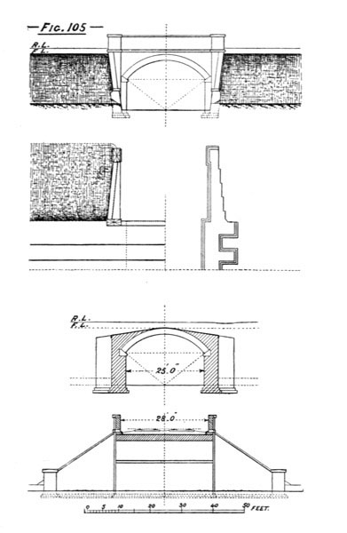
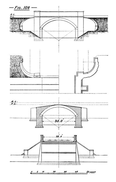
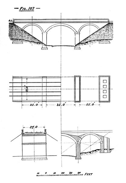
Fig. 106 shows a similar under-line bridge, but with curved instead of straight wing walls.
Fig. 107 is an example of an under-line arch bridge in a rather high embankment, and where side arches have been adopted instead of long wing walls.
The above six types are equally applicable for private roads crossing the railway, but, as previously mentioned, a lesser width and headway will be accepted for under-line bridges for private or occupation roads, than for public roads. For the over-line bridges, however, the width and headway will be regulated by the number of lines and standard height of the railway.
When these arch bridges have to be built on the skew to suit an oblique crossing of the road, extra care will be necessary in setting out the work, and marking on the centering the spiral courses of the arching.
Arch bridges may be built of masonwork or brickwork, or a combination of the two. If the available quarries do not yield good flat bedded stones readily worked, it is better, where possible, to use strong hard bricks for the arching, and utilize the stone for the remainder of the work.
Although arching undoubtedly forms the most durable type of bridgework, numbers of cases occur where the available height or space between rail-level and road-level is too small, or the cost of masonry and brickwork too great, to admit of anything but girder-work. Detailed sketches of some of the many forms of girder bridges are given in Figs. 132 to 153, illustrating various systems of roadways and parapets. In some instances the main girders are made sufficiently deep to serve as parapets, while in others a shallower girder has been adopted, on top of which has been placed a light cast-iron parapet composed either of close plate-work or of ornamental open railings. The open ironwork parapet has a good appearance, but as a screen is not so efficient as the close cast-iron plates.
In addition to the bridges required for the regular public roads, it is usually necessary to construct a certain number of occupation or private road bridges over and under the line to accommodate portions of estates and large properties intersected or severed by the railway, and which would be inadequately provided for by ordinary gate crossings on the level. The position and description of these occupation bridges is generally matter of private arrangement. The bridges will be somewhat similar in character to the public road bridges, but of much less width for the roadway. Those over the railway must have the standard span and height adopted as a minimum for the other over-line bridges, and those under the railway must have the full width on the top for the lines of rails, but will have less width between the abutments for the roadway.
Foundations.—So much depends upon the soundness and security of the foundations of any bridge, viaduct, or large building, that it would be almost impossible to devote too much care to the selection and treatment. Unless the foundation be firm, the entire structure will be exposed to the risk of failure, either in subsidence of masonry, giving way of arches, or depression of girders. A small matter overlooked during the construction of this part of the work will be most difficult to correct or adjust afterwards.
The insistent weight of all structures built of masonry or brickwork will cause the mass to settle to a certain extent, according as the joints of mortar or cement become compressed by the number of superincumbent courses. In a similar manner the gravel and clay of a foundation will compress more or less according to its compactness and the weight of the structure. No inconvenience will, however, arise if the settlement or compression be uniform throughout the entire area.
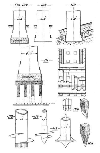
In ordinary average, dry, solid ground, a good foundation can usually be obtained at a moderate depth. The removal of a few feet of the surface layers will generally lead to a good hard stratum of natural material sufficiently firm to carry the abutments and piers of railway bridges and viaducts. Two or more footings are usually adopted so as to distribute the weight over an increased area, as shown in Fig. 108.
Where the weight to be carried is considerable, it is better to increase the number of the footings, and give them a smaller projection, as in Fig. 109, rather than have a lesser number and greater projection, as in Fig. 108. There is greater liability of fracture of the material in the latter than in the former.
Care must be taken to distinguish between made ground and natural ground. Hollows which have been filled in must not be relied upon to sustain heavy weights; the material may have been consolidating for years, but it is safer to cut through it and found upon the natural stratum beneath.
Soils of a clayey nature must be dealt with very cautiously. If the ground be fairly level, and the material firm, a solid foundation may be obtained, but the excavated portion should be covered up as quickly as possible to prevent any decomposing action taking place upon exposure to the open air. The expansive nature of some clays must be carefully kept in view, so as to guard against any disturbance in the finished foundation. There are some descriptions of shale which when first opened out appear to have the solidity of hard rock, and yet, after a few days’ exposure to the atmosphere, are changed to the consistency of soft mud.
Sand, being composed of such small particles, is almost incompressible, and makes an excellent foundation so long as it can be retained in its position. Little or no settlement will take place if the sand remains undisturbed, but so soon as it comes under the influence of running springs, or underground drainage, the fine particles of the sand will be gradually but surely carried away with the water, and the entire foundation be undermined. The opening out of a neighbouring excavation, or the carrying out of some low-level drainage, would endanger a construction which otherwise would be solid and permanent.
In many cases of soft ground, more particularly abroad, sand piles have been adopted and have given very good results. The system is carried out by first driving a large wooden pile down through the soft material into the more solid stratum below. The timber pile is then carefully withdrawn and the cavity filled with clean sand. The number and distance apart of these sand piles will depend upon the nature of the ground and description and weight of structure to be carried.
Clean, compact gravel is one of the best materials to build upon, being almost incompressible and quite unaffected by exposure to the atmosphere. It is easily excavated and levelled off to the surface required.
A foundation of rock may be considered in the abstract as the most solid base to be obtained, but it must be treated judiciously, and a proper surface secured. The outer portion of many descriptions of rock consists of blocks or layers of stone partially or entirely separated from the main bed, and these, lying in a loose condition, are deceptive and treacherous as a foundation base. The exposed rock should be carefully examined, and all detached or outlying pieces or layers removed before placing any foundation course. Special care must be paid to all shelving rock, and a level seating cut into it for the entire width of the foundation, as shown in Fig. 110.
A thick bed of concrete, as in Fig. 109, makes an excellent foundation course. When firmly set it becomes one solid massive base from end to end, and prevents the yielding or dropping of masonry at any intermediate points.
There are many places in soft, wet ground where instead of attempting to excavate all the soft material down to a harder stratum, it is better to adopt timber pile foundations, as shown in Fig. 111. The size of the piles and their distance from centre to centre must be regulated by the description of material into which they have to be driven and the weight they have to sustain. Double waling pieces should be properly checked and bolted on to the heads of the piles, and trimmed or levelled off to receive a double floor of thick planks. The spaces round the heads of piles and walings should be filled in and levelled up to under side of flooring, with cement concrete.
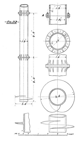
For bridges of moderate span, over soft ground or over shallow fresh water, strong cast-iron screw piles can be adopted with great advantage. Fig. 112 shows a very usual form of screw pile, made with an external screw at the lower end and with a sharp cutting edge to facilitate penetration into the ground. The upper portions are made in suitable lengths, and all to one pattern and template, for convenience in carrying out the work. The screwing into the ground is generally effected by means of a capstan or cross-head fixed to the top of the first working length of pile, and which is pulled or turned round by ropes worked from stationary windlasses. In some cases long bars or levers are attached in radiating positions to the capstan-head, and a number of men are employed to walk round and round, pushing the levers, and in this way screwing the pile into the ground. As the pile goes down the capstan-head has to be removed, and additional lengths bolted on, until the pile enters a solid stratum, or is considered deep enough for the duty it has to perform. The last or top length has generally to be cast to a special length to bring the work up to the exact height to receive the girders. The core of excavated material passes up into the interior of the pile, and in some cases becomes so compressed or tight as to require the use of an internal augur to remove a portion of it to enable the screwing to proceed. The pile shown in Fig. 112 is one of a number which were successfully screwed into the ground to depths varying from 42 to 48 feet. A toothed or serrated edge, as in Fig. 113, is sometimes given to the lower edge for screw piles which have to cut their way through a hard stratum.
All bolting flanges should be accurately turned and fitted to ensure close, parallel surfaces when bolted together.
The joint shown at A, Fig. 112, is one the writer has used to a large extent for the bolting flanges of cast-iron screw piles and cylinders. It is very simple in form, readily coated with white lead to ensure a water-tight joint, and as the upper length is practically recessed, or let into the lower length, the exact continuity of the different castings is secured.
Solid screw piles of wrought-iron or steel, similar to Fig. 114, are used for some descriptions of work. These are generally made in long lengths, in sizes varying from 4 to 8 inches in diameter, and with screw blades of wrought-iron or cast-iron fixed in the most secure manner to resist the strain produced when screwing into the ground. The couplings for these solid piles must be very carefully made, all contact surfaces truly faced and fitted, bolts turned, and bolt-holes drilled.
Fig. 115 is a sketch of a hollow cylindrical water-jet pile, which has been used successfully in cases of light sand. The lower end of the pile is made externally in the form of a solid disc, terminating in a conical point, having an aperture in the centre to correspond to the water-jet. To the top of the pile is secured a tight-fitting cover through which a tube passes from a force pump. Water at high pressure is pumped into the tube, and as it forces its way out through the conical point the sand is stirred up and loosened, and thus allows the pile to descend. When the pile has been lowered to a sufficient depth the pumps and tube are removed, and the sand settles down into its former compact condition.
Great care must be used with the first two or three lengths of any screw pile to ensure the pile taking a correct or true vertical position. Each series of screw piles should be properly braced together to obtain stability under moving loads.
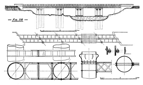
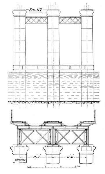
Hollow cylinders of cast-iron, wrought-iron, or steel form most efficient foundations or piers for large bridges over soft ground or fresh water of considerable depth. Made open at the bottom, and constructed of complete rings, or, if of large diameter, of rings built up in segments and securely attached together with water-tight joints, the cylinder is placed in its proper position on the ground or lowered into the water preparatory to sinking. The lower length is made with a sharp cutting edge to facilitate penetration. By excavating and removing the material round the cutting edge and base inside the lower length, the cylinder descends gradually either from its own weight or by assisted weights, and length after length is added until it is sunk to the depth required. The excavated material is filled into buckets and hoisted to the surface by a winch fixed on the top length. When sinking in water the working top of the cylinder is always kept at a suitable height above the water for convenience in removal of the earth or clay from the interior to barges or gangways alongside.
Some strata are more favourable for cylinder sinking than others. Material of a strong clayey nature admits but a small amount of water into the excavation, and a moderate-sized pump will keep the working fairly dry until considerable depth has been reached. Some other materials are so open that the water cannot be kept down with ordinary pumps, and the cylinders can then only be lowered by the pneumatic process. This process has been carried out in two methods, one of them on the vacuum principle, and the other by air pressure, or, as it is termed, the plenum system. With the former method the cylinder is placed in position, and an air-tight cap, through which a pipe passes, is secured on the top. Powerful air-pumps are then set to work, and the partial vacuum thus created in the interior causes the material round the cutting edge and base to be loosened and drawn into the cylinder, the cylinder at the same time going down or sinking by its own weight, or assisted, if necessary, by added weights. The cap is then taken off, and the material removed from the interior, the operation of exhausting and emptying the interior being repeated until the cylinder is sunk to its proper depth. This method has been found to work well in strata which contained a large proportion of clay to assist in excluding the air and water, but was not nearly so successful when applied to material containing stones and large boulders.
The plenum process is based on the principle of the diving-bell, the water being prevented from entering at the bottom by keeping the cylinder full of compressed air. An air-chamber, or air-lock, with perfectly air-tight joints, is securely fixed to the top or upper working length of the cylinder, and no access can be obtained to the interior of the cylinder without passing through this air-lock, which has one lower door or valve opening into the cylinder, and an upper door opening out into the open air. Temporary inside staging is formed by putting planks across from flange to flange, and placing short ladders on these landings for the use of workmen descending or ascending. The excavated material is hoisted by a winch, generally placed on the landing just under the air-lock. The air-pump is placed in some convenient position outside, near at hand, the pressure-pipe passing through the air-lock into the interior of the cylinder. Air is forced into the cylinder to a pressure sufficient to drive out and keep out the water from the interior, and allow the workmen free access for excavating the material round the cutting edge and base of cylinder. The amount of pressure required will depend upon the depth of the working below the level of the water alongside. Men accustomed to the process can work without much inconvenience under a pressure of 20 to 22 pounds per square inch, equal to a depth of 45 to 50 feet; but when the pressure exceeds 25 pounds, the duty becomes very trying, and is attended with considerable risk. Instances are recorded of men working at depths of 105 and 110 feet, necessitating a pressure of over 45 pounds per square inch; but it is very questionable whether the men exposed to such a severe ordeal were not permanently affected, if some of them did not actually succumb.
It will sometimes occur that, after sinking through soft porous strata to a considerable depth, a layer of clayey material is penetrated sufficiently retentive to keep out the water and permit of the removal of the air-lock and the completion of the sinking as an open-top cylinder.
When working on the plenum system everything must pass through the air-lock, both materials and men. The excavated material is hoisted up to the level of the air-lock, the upper and lower doors of which must be closed, and the pressure inside the air-lock brought to the same as that inside the cylinder by means of a regulating valve. The lower door is then opened to admit the excavated material, and then closed again to cut off all communication with the interior of the cylinder. The upper door is then opened, and the material hoisted out into the open air. The same process has to be adopted for the egress of the workmen, and the reverse arrangement for the ingress of men and materials. The shape and dimensions of the air-lock may be varied according to circumstances, but the principle will remain the same.
When the cylinder has been lowered to what is considered a sufficient depth, it is usually loaded with a certain amount of dead weight in the shape of old iron or other convenient material, and allowed to remain loaded for some days to ascertain if it will sink any further. Should this test be found satisfactory, the dead weight is removed, and the interior of the cylinder pumped dry and carefully filled with good cement concrete.
Cylinders for foundations are generally made circular in section, that form being the most convenient for turning and facing the flange-joints. They can, however, be made oval in section, or of any section that may be found most suitable for the work required. Figs. 116 and 117 give the particulars of a double-line railway bridge carried on cylinder piers across a river. The detail sketches explain the form of cutting edge, flange joint, and method of bracing. This bridge is one that was reconstructed and widened from a single-line to a double-line bridge. Traffic was carried over on one line while the second line was being erected, hence the reason why one strong central girder was not adopted.
Cylinders of 7 feet diameter and upwards are sometimes filled with concrete in the lower portion, on which is built either a circular lining or a solid mass of masonry or brickwork up to the level of the girder-blocks. In some cases the cylinders proper, together with their concrete filling, terminate a little above the water-level, and upon these foundations are erected strong cast-iron columns, plain or ornamented in design, to carry the girders and roadway. The cylinder itself is generally considered merely as a casing or medium for obtaining a foundation, the weight of the superstructure being carried on the internal filling or lining.
Caissons constructed of plates of wrought-iron or steel are much used for the foundations of large piers in deep water. Practically they may be considered as cylinders on a large scale, with the difference that whereas cylinders are generally continued up to the under side of the girders of the superstructure, caissons are only carried up to a short distance above the water-level. A caisson forms a strong water-tight iron cofferdam, from which the water can be excluded, and a masonry or brickwork pier constructed inside. It may be made all in one piece to correspond to the form of the pier, or in separate pieces to form one whole, each being sunk independent of the other, and connected together afterwards. Being built up of plates cut to the proper size and shape, it is a very simple matter to rivet on additional tiers of plates as the caisson is lowered deeper and deeper into the bed of the river. The lower length is made with a cutting edge to penetrate the ground; the exterior is made without any projection larger than the rivet heads, and the interior is strengthened with T-irons or double L-irons at the joints, and strong cross-bracing to resist the pressure of the water. About 7 or 8 feet above the cutting edge a strongly framed iron floor is riveted to the vertical sides, and strengthened by plate-iron under-brackets placed at short distances. The excavators work in the space below the floor, and the excavated material is passed up through openings formed in the floor at convenient points to suit the working. The methods of lowering a caisson are the same as for lowering a cylinder. If the pneumatic system has to be adopted, then two or more air-tight tubes of liberal dimensions (say 5 to 8 feet diameter), according to the size of the caisson, must be attached to the floor, and on the top of each of these tubes air-locks must be secured for the removal of men and materials. The masonry or brickwork of the pier is built upon the iron floor, and a portion of this building work is usually carried on during the sinking of the caisson to obtain weight to assist in the lowering. When down to the proper depth, the space below the floor is properly cleared of débris and water, and then carefully filled in with cement concrete.
Some caissons are made with vertical sides throughout their entire height; others have an outward taper for 15 or 20 feet on the lower end. The former are not only simpler in construction, but are more easily kept in a vertical position during the sinking. Caissons are usually put together in some convenient place near the edge of the water, and then conveyed on pontoons to the sites of the piers. Great care is required in lowering them into position in the bed of the river, and guide-piles, guy-chains, and other appliances are frequently necessary to keep them vertical during the sinking.
The form, dimensions, thickness of plates, cross-bracing, and general arrangement will depend upon the size and depth of the pier to be constructed. Caissons for heavy work on difficult or treacherous ground require great care, not only in their construction, but also in placing them in exact position, and in sinking them correctly to their proper depth. A tilted caisson is a most difficult subject to handle, and entails heavy expenditure to restore it to a true vertical position. By making careful borings, the engineer can ascertain very closely the depth to which the caisson will have to be lowered to obtain a good firm foundation. With this information the caisson can be so constructed that the upper portion, termed the temporary caisson, commencing a few feet above the bed of the river, can be detached, and removed at the completion of the work from the lower or permanent portion sunk below the ground line.
Fig. 118 gives sketches of a wrought-iron plate-caisson applied to a deep-water river pier, and lowered to its full depth by the pneumatic process; dotted lines show the air-tubes through which the excavated material is hoisted and emptied into barges alongside.
Many large and important pier foundations have been constructed on the system of brick cylinders or wells, particularly in India, where the foundations for large river viaducts have to be carried down to great depths through thick deposits of soft material. These wells are built upon V-shaped curbs to facilitate the penetration when sinking. Fig. 119 is a section of a well with a wrought-iron curb, and Fig. 120 is a similar well with a wooden curb. The wrought-iron curb is made in segments for convenience of transport, the pieces forming the complete ring being bolted or riveted together at the site of the foundations. The wooden curb is composed of several thick layers of hard wood planking cut to the proper shape, and laid with broken joints, the whole being bound together with suitable bolts and spikes. In some cases the lower or cutting edge of the wooden curb is strengthened or protected by a sheathing of wrought-iron plates.
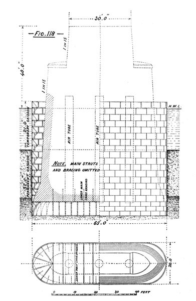
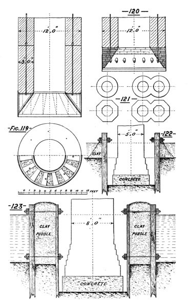
Well foundations are usually put in when the rivers are at their lowest, and reduced to a few small channels in the great width of dried-up river bed. This condition enables the greater portion of the curbs to be conveniently and accurately placed in position on dry ground, or on ground which, although soft and muddy, is not covered with water. Should the site of one of the wells occur in one of the small channels, the stream can be diverted to one side, and a small artificial island made to receive the curb above water-level. When a curb is fairly fixed in position, the work of building the brick well can be commenced. With the wrought-iron curb the triangular cavity between the vertical plate and sloping plate must be filled with concrete to form a level base for the first course of brickwork. The wooden curb being composed of horizontal layers of timber, is ready to receive the brickwork without further preparation. To strengthen and keep the brickwork firmly tied together, strong wrought-iron vertical tie-rods, 1¼ or 1½ inch in diameter, are generally built into the work—as shown in the sketches—at distances about four feet apart. The lower end of the bottom tier of tie-rods is secured to the curb, and the upper end passed through a strong wrought-iron plate-ring, which is continuous all round the brickwork. A long deep nut is screwed down over the top or screwed end of tie-rod until the plate-ring is down tight on the brickwork. The tightening nuts are made sufficiently deep to receive the lower ends of a second series of vertical tie-rods, which in like manner pass through another wrought-iron plate-ring on the next section of brick well, and the same arrangement is continued for the full height of the well. The lengths of the tie-rods will depend upon the lengths of the section of brickwork to be built at a time, and may vary from 10 to 15 feet.
As the work of building proceeds the curb and brick well will sink gradually into the ground, and down to a certain depth, varying according to the material of the river bed, the weight of the brick well itself will effect the penetration and lowering. Beyond this depth the lowering must be done by scooping or dredging the material from the inside of the well, and placing heavy weights of old railway iron or other convenient masses on the top. When one section or length of well has been sunk down, then another set of tie-rods are inserted into the deep nuts, and another section of brickwork commenced. The operation of lowering is rather tedious, as all the weights have to be hoisted up on to the top of the length in hand, and piled so as to leave space for lifting out the material dredged from the interior; and then, when the length has been lowered, all the weights must be removed before the brickwork can be resumed on another length. Where the river bed consists of soft material, the excavation inside the well can generally be effected by suitable dredges or scoops worked from the surface or top of brickwork. Should trees or other obstructive masses be met with embedded in the strata, it will be necessary to employ divers to remove them piecemeal out of the way of the curb.