Chapter II · (continued 2)
Reading edition
When the brick well has been lowered down to the full depth, and is thoroughly bedded in a stratum of strong material, the test weights should be left on for some time to ascertain if there is any further sinking. After all the weights have been removed the bottom of the well can be dredged out clean, and the interior filled in with concrete to such height as may be considered necessary.
Brick wells must be watched carefully to ensure that they sink down in a perfectly vertical position. Any inclination away from the perpendicular must be corrected at once by means of guys and struts, the same as in sinking iron cylinders. The principal difficulty will be with the first 20 or 25 feet.
The diameter of the well will depend upon the weight it has to carry, and its height from river bed to under side of girders. The wells may be either circular or polygonal in section, and built singly or in pairs, as shown in sketches (Fig. 121).
Many piers and abutments of bridges in shallow or moderately deep water are built by means of coffer-dams of timber and clay puddle. The coffer-dam forms a water-tight wall round the site of the foundation, from which the water is pumped out, and the excavation carried down to the depth required. In very shallow water it is sometimes sufficient to drive only a single row of piles, and form a bank of good clay puddle on the outside, as shown in Fig. 122. In deep water it is necessary to drive a double row of piles, 3 or 4 or more feet apart, and fill in the space between with clay puddle, as shown in Fig. 123. The piles for coffer-dam work should be carefully selected, of good timber straight, and correctly sawn on the contact faces. Guide-piles are first driven in proper line and position round the intended foundation. To these strong horizontal double waling pieces are securely bolted, one on each side of the guide-pile, one pair near the top, and the other pair as low down as can be placed. The sheeting piles, which are lowered down between the horizontal waling or guiding pieces, are driven as close to one another as possible, being assisted in doing so by the sheet-pile shoe, shown on Fig. 124, which is made not with a point like an ordinary pile shoe (Fig. 125), but with a cutting edge slightly inclined, so that in driving the tendency of the pile is to drift towards the pile previously driven. Sometimes the outer row of piles consists of whole balks, and the inner row of half balks; the size of the piles must, however, be regulated by the depth and current of the water. When both rows of piles have been completed, the space between should be dredged out, and then filled with carefully prepared clay puddle. To enable the puddle to adapt itself thoroughly to the wooden sides, it is desirable to remove the inside walings after all the piles are driven, as any internal projections interfere with the proper punning and settling of the puddle. The swelling of the puddled clay has a tendency to force apart the two rows of piles, and to counteract this as much as possible, iron tie-rods should be passed through from side to side every few feet, and screwed up against large washers placed on the outside of the outer walings. Strong struts or cross-bracing of timber must be placed from side to side inside the coffer-dam to resist the pressure of the water in the river. This cross-bracing can be removed gradually as the work of building progresses upwards, and be replaced with short struts wedged in against the sides of the finished courses.
In cases where the ground is soft, and when it is not considered prudent to excavate the foundations deeper for fear of disturbing the stability of the coffer-dam piles, rows of large, square bearing-piles may be driven in the floor of the foundation, as shown in Fig. 111. The tops of these bearing-piles must all be sawn off to the same level, and a platform of strong double planking securely fixed to the piles to receive the foundation course of concrete, masonry, or brickwork. The spaces around the tops of the piles and the under side of the timber platform should be filled in with good cement concrete.
The interior of the coffer-dam is kept dry by constant pumping, either by hand pumps or steam pumps, according to the volume of water finding its way into the foundations. When the finished pier or abutment has been carried up above the river water-level, the coffer-dam is no longer required, and may be removed. Sometimes, to save the timber, the piles are drawn by means of strong tackle fitted up for the purpose; but in doing this there is considerable risk of disturbance to the foundations, and it is better to leave the piles in the ground and employ divers to cut off the tops a little above the bed of the river.
In preparing the design for a large foundation it is absolutely necessary to first ascertain by careful borings the description of material upon which that foundation must be placed, so as to proportion the area of bearing surface to the weight to be sustained. Some materials will naturally carry more weight than others, and although the engineer cannot always select the material he would prefer, he can, however, control the superficial area of the foundations. Much valuable information has been obtained both from experiments and from comparisons of actual practice, and the following memoranda may be useful for reference, as indicating the pressures per superficial foot which may be safely put on various materials:—
Moderately stiff clay2½ tons.
Chalk4 ”
Solid blue clay5 ”
Compact gravel and close sand6 ”
Solid rock12 ”
Doubtless the above weights have been exceeded in many cases, but it is better to be on the safe side, and leave a good margin for stability.
Large subaqueous foundations for heavy piers and abutments are costly and tedious, and especially so when the pneumatic process has to be adopted. Special appliances and well-trained, experienced workmen are requisite, and if all the men and materials have to pass through the air-locks, the progress of the work must necessarily be slow. When the foundations have been completed up to the level of the water, the construction can be pushed on more rapidly, as the work of scaffolding, hoisting, and building, can all be carried on in the open air.
Amongst the very many types of arch-work and girder-work adopted for railway purposes, the following examples from actual practice may be useful for reference:—
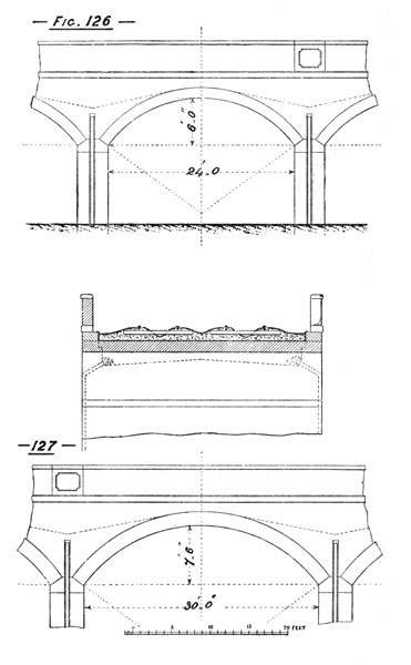
Fig. 126 represents small 24-foot span, low viaduct arching suitable for a line passing through towns or villages, where ground is valuable and the area to be covered must be kept as small as possible. The arches may be utilized for stables, stores, or roads of communication between the lands and properties intersected by the railway. The segmental form gives a better headway underneath than the semicircular, besides containing less material in the arching proper, and requiring a smaller amount of centering. Every precaution should be taken to prevent water percolating through any portion of the arching, or haunching, and a thick layer of good asphalte should be placed over the entire upper surface, and carried well up the lower portion of the parapet walls, as shown on the sketch. The cast-iron pipes with rose heads form a very efficient means of taking away the rain-water which filters through the ballast and filling. The pipes should be carried down in chases, or recesses, built in the fronts of the piers, to protect them as much as possible from injury in the yards below. Rose heads, pierced with holes, and surrounded with small stones hand-laid, serve well to conduct the water into the pipes. Where the arching is of considerable length, recesses or refuges for the platelayers may be obtained by substituting a short length of cast-iron-plate parapet, instead of the stone or brick parapet, over some of the piers, as indicated in the sketch.
Fig. 127 shows a similar description of arching for spans of 30 feet. The above two examples represent plain substantial work, but if circumstances warrant more external finish, this can readily be added without interfering with the general arrangement. In a similar manner, if considered preferable, the arches may be made semicircular or elliptical.
In the sketches shown of the arched over-line and under-line bridges, the arching and coping of parapets are in brick, and the remainder of the work in stone. In very many cases brick will be found cheaper and more expeditious for arching than stone, unless the quarries turn out stone in blocks which can be conveniently trimmed for arching. All bricks used for arch-work should be hard and well burnt, and special care should be taken in the selection of those to form the under-side course, which will be exposed to the atmosphere. For moderate spans arches have been successfully constructed of concrete. For this description of work the materials should be carefully gauged and mixed together, and the finished work should be allowed to stand some time on the centres to allow the concrete to become thoroughly set.
In Fig. 102, the cutting being deep, almost up to the level of the public road, the foundations of the wing walls are built in steps, resulting in a minimum of masonry below the finished ground line. Where the cutting is shallow, and the public road has to be brought up to the bridge on an embanked approach, the greater portion of the wing walls will have to be built up from the solid or original ground, and there will be a large amount of masonry below the finished ground line, as indicated in Fig. 128.
In some cases of over-line bridges it is necessary to curve the wing walls to correspond to the road which turns off to the right or left after crossing the railway, as shown in Fig. 129; or the wing walls may have to form two separate curves where the road branches off in two directions after leaving the bridge, as shown in Fig. 130.
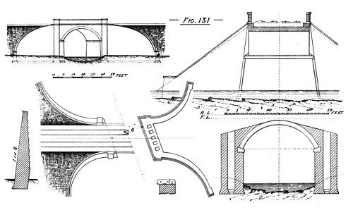
Fig. 131 shows plan, elevation, and cross-section of an under-line arch bridge, considerably on the skew, carrying a railway over a river. The wing walls are curved, and very similar in type to some of those in preceding examples. The river bed and ground alongside being of solid rock, good foundations were obtained at a very moderate cost.
On many railways constructed in the beginning as single lines only, the over-line bridges have been built for double line. The additional cost in the outset has been small, compared with the great expenditure which would be incurred afterwards in reconstructing the bridges to suit a double line.
The general arrangement of abutments and wing walls shown in the foregoing examples will apply to similar classes of bridges where girder-work is adopted instead of arching.
There are many ways of forming the floor or deck of a girder bridge intended to carry a railway over a road or stream. In some cases it will be imperative to have a thoroughly water-tight floor to prevent rain-water percolating through to the roadway below; while in others, such as bridges over streams, and secondary roads, this special provision will not be necessary, and a lighter and more economical floorway can be adopted. A strong wrought-iron or steel-plate flooring, with its corresponding filling and ballasting, means not only so much additional cost in the flooring proper, but also so much additional dead weight to be carried by the main girders.
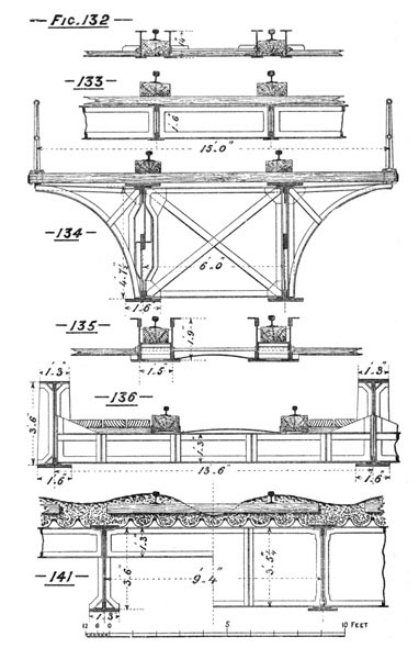
Fig. 132 is a sketch of rolled joist-iron I-girders and timber floor frequently adopted for small farm roads and cattle creeps of 10 or 12 feet span. A beam of timber is fitted in between the two rolled joist-irons, and the three pieces securely fastened together with strong iron bolts placed about 3 feet apart. These small compound girders rest on bearing-plates of wrought or cast iron, and are held together and to gauge by tie-rods, as shown. The rails are spiked or bolted down on to the timber beams, and the flooring formed of strong planking.
Fig. 133 shows an arrangement of plate girders for a 16-foot opening over a stream. The girders are placed immediately under the rails, and are tied together by plate-iron cross-bracing the same depth as the main girders. The flooring consists of 4-inch planking laid with ¾-inch spaces, on which are laid longitudinal rail-bearers 14 inches wide by 7 inches thick.
Fig. 134 is a sketch of a somewhat similar arrangement for a lattice-girder bridge, 45 feet span, carrying a single line of railway over a river. The main girders are tied together by lattice-work cross-bracing. The floorway consists of 5-inch planking, laid with ¾-inch spaces, on which is placed the 14 feet by 7 feet longitudinal rail-bearers. Plate-iron outside brackets are riveted to the main girders to carry the ends of the planking and light tube-iron parapet.
Fig. 135 illustrates an example of trough girders, constructed to carry a double-line railway over a country road 25 feet wide, where the space from under side of girder to rail-level is small. The girders are constructed in pairs, with short, shallow cross-girders at 3 feet 6 inch centres, riveted in between them to carry longitudinal timbers on which the rails are laid. Bottom plates, 5/8 inch thick, unite the two girders for the length of their bearing on the abutments, and a similar plate, 9 inches wide, unites them at the centre; the remainder of the span is left open to prevent the lodgment of rain-water. Three strong tie-rods are placed to keep the girders to gauge. Curved wrought-iron ballast-plates are used between the running-rails, and plank flooring forms the rest of the covering.
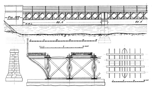
Fig. 136 is a sketch of a plate-girder bridge over a country road 28 feet wide, with the load carried on the lower flange of girder. Three main girders carry the double line of railway, the centre one having double the strength of each of the outside girders. On the top of the cross-girders, strong angle irons are riveted to serve as guides and supports for the longitudinal timbers which carry the rails. Every third cross-girder has raised ends to give increased lateral stability to the main girders. A close cast-iron plate parapet forms a screen to the roadway. Wrought-iron ballast-plates are used between the running-rails, and the remainder of the flooring is of timber.
Fig. 137 gives the particulars of one 60-foot span of a viaduct carrying a double line of railway over tidal water. The main girders are placed one under each line of rails, and all the four are strongly tied together by lattice-work bracing the full depth of the girders. The outside footpaths for the platelayers are carried on strong brackets, riveted to the main girders. Longitudinal timbers, coped with angle iron, are placed as outside guards, alongside each rail, for the full length of the viaduct. Wrought-iron ballast-plates are placed between the running-rails. The remainder of the footways consist of timber planking, laid with half-inch spaces, and covered with a layer of small pebbles as a protection against fire.
Fig. 138 shows a very similar arrangement in a viaduct carrying a single line of railway across a river. The two main lattice girders—66 feet span—are placed at 9-foot centres, to obtain greater stability. The cross-girders are extended to carry the outside footpaths and handrailing. Outside guards are placed alongside each rail as in the preceding example. Wrought-iron ballast-plates are fixed all along between the running-rails, and timber planking used for the rest of the floorway.
Fig. 139 gives cross-section of a lattice-girder bridge, 82 feet span, carrying a single line of railway over a river, with the load carried on the lower flange. The cross-girders are placed at 4 feet 3 inch centres. Wrought-iron ballast-plates compose the floorway between the rails, and timber planking covers the rest of the bridge. Plate diaphragms, or stiffeners, of the form shown at A, A, A, A, are riveted to the main girders at five places in their length.
Fig. 140 shows cross-section of a lattice-girder bridge of 200 feet span, carrying a single line of railway over a river, the load being placed on the lower flange. The floorway consists of plate-iron cross-girders, spaced at 4-foot centres, on which are placed the longitudinal rail-bearers and planking, the latter being covered with a layer of clean pebbles for the width between the running-rails. As the depth of the main girders was sufficient to admit of overhead bracing, strong plate-iron diaphragms, of the form shown on the sketch, were riveted to the main girders at every 50 feet. These diaphragms thoroughly brace the two girders together, and effectually prevent any tendency to side-canting, at the same time imparting an effective appearance to the bridge.
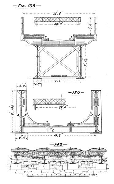
Fig. 141 shows cross-section of a plate-girder bridge, of 36 feet span, carrying six lines of way across a street. Strong plated cross-girder bracing, at 4 feet 8¼ inch centres, is riveted to the main girders, and the top is covered with old Barlow rails, 12 inches wide, and weighing 90 lbs. per lineal yard. A layer of asphalte, about 1½ inches thick, is carefully laid all over the upper surface of these rails to make a thoroughly water-tight floor. Clean gravel is placed on the top, on which are laid the sleepers and rails of the permanent way. Rain-water passes through the gravel into the hollows of the Barlow rails, and finds its way into suitable drains provided at each abutment. This arrangement not only prevents the falling of drip-water into the street below, but permits of the alterations of the lines of way, or putting in of cross-over roads on the surface above. The outside main girders are made deeper, and are surmounted by close cast-iron parapets.
Fig. 142 gives the particulars of a three-span plate-girder bridge, constructed to carry a double line of railway over two other railways and a canal, the load being placed on the lower flange. Two main girders are used for each line of way. Strong plated cross-girders are placed at 5 feet 3 inch centres, and on the top of these is laid a flooring of old Barlow rails, terminating at the sides with sloping wing-plates riveted to the cross-girders and main girders, the entire surface being covered with an inch and a half layer of asphalte. Good gravel ballast is placed on the top, on which are laid the sleepers and rails. One central main girder of sufficient strength would have been as efficient as the two central girders, but there was a practical difficulty which prevented its adoption. The new girder-work was built to replace an old structure of peculiar arrangement, and to keep the traffic going on one line there was no alternative but to make each line of way complete in itself.
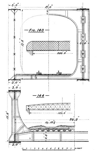
Fig. 143 illustrates an example of jack arches in concrete built between strong plate-girders. The span of the girders was only 16 feet, but the opening or roadway was of considerable length, and passed under a portion of a busy station yard. The girders are placed at 6-foot centres, and tied together in pairs by 1¼-inch tie-rods, three to the span, spaces of 6 inches in plan being allowed between each set of the rods. The concrete was curved up to the top plate of the girder, as shown, and the entire surface covered with a thick layer of asphalte, on which were placed the ballast and permanent way. Brickwork might have been used for the jack-arching, but concrete was considered more convenient.
Fig. 144 shows the cross-section of a truss-girder bridge of 123 feet span, carrying a double line of railway over a wide thoroughfare, the load being placed on the lower flange. There are two main girders, each 12 feet 6 inches deep in the centre, and 8 feet deep at the ends. Plate cross-girders are placed at 4 feet 6 inch centres, on which is riveted longitudinal plate-iron troughing, extending across the bridge and terminating at the sides with wing-plates, as shown. The entire floor is covered with a thick layer of asphalte previous to filling in with ballast to receive the permanent way. Plate stiffeners are adopted in this bridge very similar to those in Fig. 139.
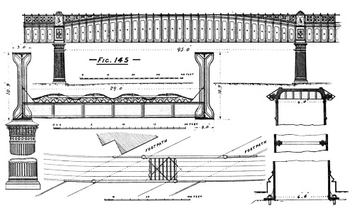
Fig. 145 gives plan, elevation, and cross-section of a plate-girder bridge of 95 feet span, carrying a double line of railway over a very busy street. There are two curved-top main girders, each 10 feet 9 inches deep in the centre, and 6 feet 7½ inches deep at the ends. The arrangement of cross-girders, longitudinal plate-iron troughing, and permanent way, is very similar to that in the preceding example, but the side wing-plates are carried up higher, and are riveted up to the web-plate of main girder, forming continuous stiffeners from end to end of the main girders. A light, ornamental, close cast-iron parapet is bolted on to the top of the curved, or upper, boom of the main girder, the top line of the parapet being carried out parallel to the bottom boom of girder. This bridge crosses the street very obliquely, and, although cast-iron columns were allowed at the edge of the footpaths, the main spans are unavoidably large. When designing the above bridge, the writer had to adopt a girder that would form a screen, to provide a deck, or floor-way, which would be not only water-tight, but also deaden as much as possible the sound or vibration of passing trains, and at the same time give some ornamental appearance to the girders and parapets. This bridge carries a constant service of heavy trains; it is perfectly dry underneath, and is remarkably free from noise or vibration.
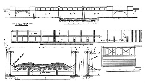
Fig. 146 shows cross-section of a plate-girder bridge of 40 feet span, carrying a double-line railway over a street, in a situation where the depth from top of rails to under side of girders had to be made as small as possible. Three main girders were used, the centre one being double the strength of each of the outside girders. Instead of ordinary cross-girders, transverse plate-iron troughing was adopted, very similar in section to the longitudinal iron troughing in Fig. 145, but stronger. The troughing rested on the angle iron of bottom flange of main girder, and was riveted to the vertical web-plates of main girders, shallow additional vertical plates being inserted alongside web-plates to prevent any drip-water or moisture coming in contact with the main web-plates. The entire surface of the troughing was well covered with asphalte before filling the hollows with gravel ballast. An ordinary transverse wooden sleeper was placed in each hollow, and on these sleepers the rails were secured as shown. In this case—as in others of transverse troughing—the rain-water had to be conveyed away from the hollow of each trough by a separate outlet into longitudinal gutters shown at A, B, and continued on to the abutments.
Transverse troughing is always more troublesome than longitudinal troughing, as both ends of each trough must be effectually closed to prevent the drainage water leaking out on to the web-plates, or angles of the main girders. With longitudinal troughing the water is readily carried away from each hollow, to cross drains constructed at the piers, or abutments.
Fig. 147 shows cross-section of a truss-girder bridge, 120 feet span, carrying a single line of railway over a river. The cross-girders are placed at 10-foot centres to correspond to the vertical members of the main truss-girder. Longitudinal plate-iron rail-girders are riveted in between the cross-girders, and the entire floor is covered with curved wrought-iron ballast plates, as shown. The rails are carried on longitudinal timbers, which are bolted on to the rail-girders. Angle iron brackets, riveted on the top of the cross-girders, keep the rail timbers in position and gauge.
In each of the above examples, where longitudinal rail timbers are adopted, flange rails are shown, as many engineers prefer to have a continuous bearing for the rails on bridges, in case of rail fracture. There is nothing, however, to prevent the chair road being laid on longitudinal timbers, and for this purpose the writer has used chairs of the ordinary pattern, specially cast with side lugs to grip the timber, as shown in Fig. 148. Chairs of this form have a very firm hold on the longitudinal timber, and the side lugs check any tendency of the splitting or opening of the wood when putting in the spikes or screw bolts.
Fig. 149 shows cross-section of a plate-girder over-line bridge, 32 feet span, carrying a private road, 12 feet wide, over a double-line railway. The road traffic being small, the floorway was constructed of creosoted planking carried on rolled I-iron cross-girders placed at 3 feet 8 inch centres, and riveted to the main girders. The horse-tread track was provided with a second layer of planking, laid transversely, to take up the wear, cross battens, 4 inches by 2 inches, being placed at 12-inch centres, and sand spread between to give good foothold. A light lattice-work parapet was bolted on to the top of the main girders.
Fig. 150 gives cross-section of a plate-girder over-line bridge, 30 feet span, carrying a private road, 20 feet wide, over a double-line railway. The main girders are tied together by lattice-work bracing, spaced at 7-foot centres. Curved wrought-iron plates are laid across from girder to girder, and butt against a narrow horizontal plate, which forms part of the upper boom. The curved plates are riveted on to the top of girder, and form a continuous iron floor, or deck, from side to side of the bridge. Upon this iron floor is laid an ordinary asphalte roadway. The outside girders are made deeper, and carry an ornamental cast-iron parapet. In some bridges of a similar construction, the roadway is formed of creosoted wooden block paving, on a foundation of asphalte.
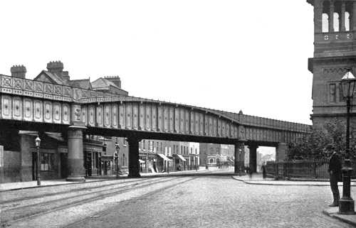
BRIDGE CARRYING THE D. W. AND W. RAILWAY (LOOP LINE) OVER AMIENS STREET, DUBLIN. [To face p. 144.
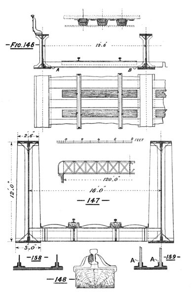
Fig. 151 shows cross-section of a plate-girder over-line bridge, 28 feet span, carrying a public road, 35 feet wide, over a double-line railway. The main girders, 2 feet 4 inches deep, are placed at 5 feet 2 inch centres, and are tied together by plate-iron cross-bracing 2 feet deep. Jack-arches of brickwork, 9 inches thick, are built in between the main girders, the haunching being filled in with concrete. The entire surface is covered over and made watertight with asphalte, on which is laid the metalling of the roadway. The outside girders are made considerably deeper, and have strong cast-iron-plate parapets bolted on to the top booms. There is no doubt that jack-arching of brickwork or concrete makes a very strong and permanent floorway, but its dead weight is very great, and its adoption is not to be recommended where iron or steel plate troughing can be obtained at a moderate price.
Fig. 152 gives cross-section of plate-girder over-line bridge, 41 feet 6 inch span, carrying a public road, 25 feet wide, over three lines of way. Two main girders are used, of sufficient depth to form parapets or screens for the finished roadway. Plate cross-girders, placed at 6 feet 6 inch centres, are riveted to the web-plate and lower angle irons of main girders; and on these is placed a flooring of plate-iron longitudinal troughing to carry the metalled roadway.
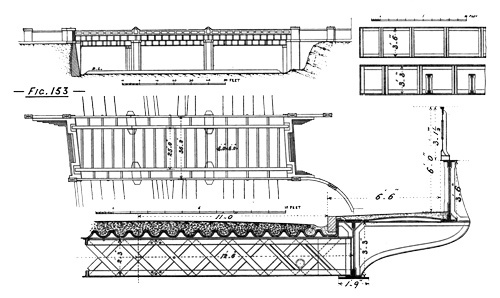
Fig. 153 gives the particulars of a plate-girder over-line bridge, carrying an important public road, 35 feet wide, over several main lines and sidings. The carriage-way is carried by two girders placed at 25-foot centres, and on the lower boom of these are riveted lattice-work cross-girders to receive the plate-iron longitudinal troughing and roadway. The footpath girders are set at a higher level, and the load placed on the lower flange. The curved side brackets merely act as bracing between the carriage-way girders and footpath girders. A cast-iron-plate parapet is bolted on to the top of each of the footpath girders, making a close screen, 6 feet high, above the footpath. Lattice-work cross-girders were adopted for the convenience of supporting small water mains and gas mains below the road-level. The roadway is formed of ordinary metalling, and the footpaths of asphalte pavement; the kerbing is of granite, and the side water-tables of crushed granite concrete.
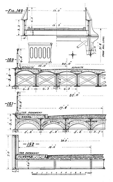
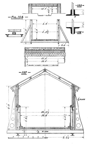
Fig. 154 is a cross-section of a small uncovered lattice-girder footbridge 41 feet span, and 5 feet wide, suitable for small roadside stations. The top and bottom flange consist each of two angle irons, those in the bottom flange being placed table side upwards, so as to bring the entire section of both angle irons fairly into play, and also to provide a better bearing for the channel-iron cross-girders which carry the planking of the footway. When planking is carried on the inside of light angle iron, as in Fig. 155, a severe strain is produced at the point A; this is entirely obviated by placing the bottom angle irons table side upwards, as in Fig. 156. Three of the channel-iron cross-girders are extended outwards, and to the ends of these are riveted tee-iron stiffeners to steady the main girders. In some cases stamped, or ribbed, wrought-iron plates are used for a footway, but, although more durable, they do not give such a secure or agreeable foothold as timber. The ascent or descent of the bridge may consist either of steps and landings, or of ramps, according to circumstances or expediency. Sometimes these bridges are made with curved tops, terminating in steps when nearing the steps, or ramps. It is very questionable whether such an arrangement is a good one or a safe one. There is always a feeling of insecurity when walking over a sloping surface broken up by steps, and experience points out that it is better to continue the footway level right across to the place where the passenger must change his direction to go down the stairs or ramp.
Fig. 157 gives cross-section of a covered lattice-girder footbridge, 62 feet 6 inches span, and 10 feet wide, suitable for an important station. The upper boom of girder consists of two angle irons and top plate, and the bottom boom of two channel irons. The cross-girders are rolled joist-irons resting on the top tables of the channel irons. Four of the cross-girders are extended outwards, and carry plate-iron outside vertical brackets to stiffen the main girders. Three-inch longitudinal planking is laid down from end to end of the bridge, and on this is laid 1¼-inch transverse flooring, in narrow widths, to form the walking deck. The footbridge is lighted from the sides by continuous glazed sashes fixed in strong wooden framework, as shown. The roof is covered with canvas bedded in white lead, and painted in the same way as an ordinary carriage roof.
The above examples of under-line and over-line bridges are given more with a view of illustrating some of the many different descriptions of flooring, rather than to point out or suggest the type of main girder to carry the load. The description and size of the main girders can be varied to suit the span of the bridge, the requirements of the traffic, and the opinion of the designer. For spans up to 50 feet it will generally be found that web-plate girders are both simpler and cheaper than lattice or truss girders; at the same time, there are occasions where plate girders can be advantageously adopted for very much larger spans, as, for instance, in the example given in Fig. 145, where the deep plate girders form a most efficient screen.
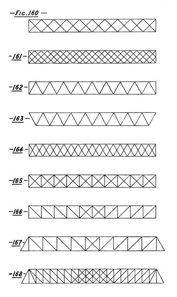
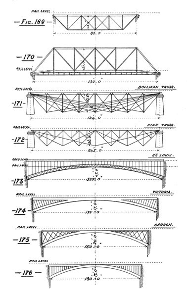
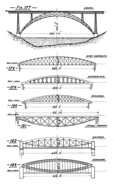
Figs. 160 to 194 give diagram sketches of a few out of the many forms of open, or truss, girders which have been adopted for large spans. There are many types from which to make a selection, each one possessing its own special features and advocates. In working out the details of any, or all of them, there are some points which should always be kept in mind when deciding the distribution of material in the main booms. Rain-water, or moisture of any kind, is the great enemy of wrought-iron or steel work, and therefore the plates, angles, tees, or channel sections, should be so arranged as to afford the least possible facility for the collection or lodgment of water. With open, level booms, as in Figs. 137, 139, 140, 144, and 145, the rain-water cannot collect, but runs off at the sides, and the plates are quickly dried by the sun and wind. With trough booms, as in Fig. 158, the collected rain-water can only get away through holes drilled for the purpose in the bottom plates. These holes are liable to become choked up, but even when open they rarely carry off all the accumulated water; some of it remains to corrode the plates, and is only dried up by evaporation. The inside of trough booms should be constantly inspected, and the exposed plates more frequently painted than the rest of the girder. In a similar manner, in small double-web lattice girders, with the lattice-bars inserted between two angle irons, as in Fig. 159, the rain-water finds its way into the spaces at A, A, in spite of the most careful packing or filling with cement or asphalte. Numbers of small girders of this latter type have had to be taken out after a comparative short life, in consequence of the great corrosion and wearing away of the lower ends of the lattice-bars and angle irons into which they were inserted.
It is most essential, also, that all portions of the girder-work should be conveniently accessible for inspection and painting. Complicated connections, and parts which are difficult to examine, are liable to be overlooked, or, at the best, only painted in a very imperfect manner. Neglected corners soon create deterioration, the paint scales off, corrosion commences, and the working section is gradually reduced. A discovered weakness in some of the important parts points to an early condemnation of the entire structure. The difficulty of access to the interior of box or tubular girders, especially those of small or moderate dimensions, is a great objection to that type of girder. Experience has pointed out that open girders, free and exposed to the light and air, can be so much more effectually inspected and painted.
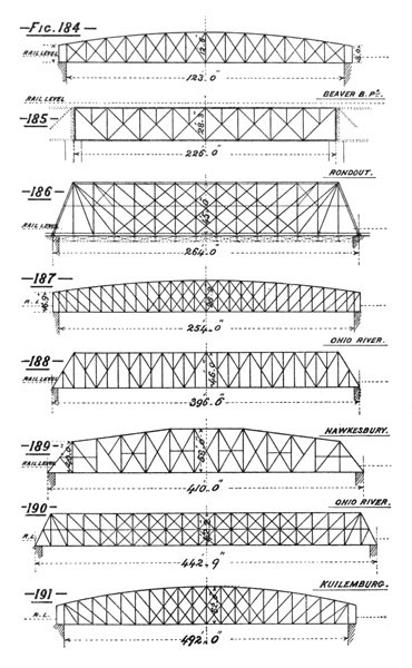
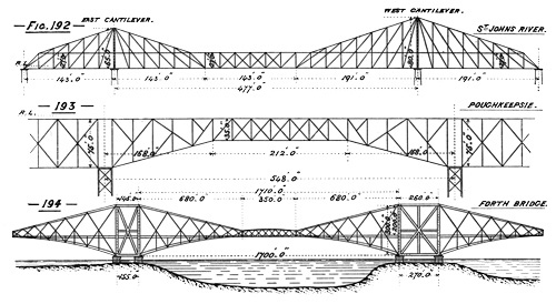
Perhaps one of the most anxious tasks which falls to the lot of an engineer is the renewal of under-line bridges and viaducts on a working line. On a new line in course of construction the entire site of the work is at the disposal of the erectors, and the building of a bridge or viaduct can be carried on with a freedom which cannot be obtained on an open line. On a working railway, the train service must be kept going, irrespective of renewals, and very often the best that can be done is to reduce the double line to single line working at the site of the operations. It is not always expedient or possible to make a temporary bridge and diverted line for traffic purposes, as the expenditure to be incurred might be too great to warrant the outlay, or there may be local difficulties to effectually prevent the introduction of a provisional structure. The taking down of one half of the old structure may necessitate the removal of stays and bracing affecting the stability of the half remaining to carry the traffic, and thus render temporary shoring and bracing necessary. The erection of the new work in such a limited space has to be watched with great care; all cranes, lifting appliances, and scaffolding must be kept clear of vehicles moving over the running-line, and very frequently it is found prudent to cease erecting operations during the passage of a train.
In very many cases of renewals, the description and arrangement of the old structure will materially influence or control the design for the new one, and the details of the latter must be schemed out so as to disturb as little as possible the stability of the old work remaining as the working road.
The following list gives the lengths of the main spans of some railway bridges, and may be found useful for reference:—
Lengths of Main Spans of some Large Railway Bridges.
Name. Span. Description.
feet.
Forth Bridge1,710Cantilever.
Niagara821Suspension.
Sukkur820Cantilever.
Poughkeepsie, U.S.A.548Cantilever.
Douro525Arch.
St. Louis520Arch.
Cincinnati515Linville truss.
Haarlem510Arch.
Kuilemburg492Lattice bow.
St. John’s River477Cantilever.
Niagara470Cantilever.
Britannia460Tube.
Ohio River, Pennsylvania442Pratt through truss.
Saltash434Tube and girder.
Hawkesberry Viaduct410Compound truss.
Conway400Tube.
Vistula397Lattice.
Spey River, Garmouth, N.B.350Bowstring.
St. Laurence330Tube.
Hamburg316Double bow.
Cologne313Lattice.
Runcorn305Lattice.
Sunderland300Bowstring.
Rondout Bridge, Buffalo264Pratt through truss.
Newark Dyke (New)259Lattice bow.
Tay Bridge (New)245Lattice bow.
Ohio River, Louisville245Fink truss.
Beaver Bridge, Pennsylvania230Pratt deck truss.
Craigellachie Bridge200Lattice.
Rohrbach Bridge, St. Gothard River197Wrought-iron arch.
Windsor Bridge187Bowstring.
Victoria Bridge over Thames175Wrought-iron arch.
Shannon River Bridge165Bowstring.
Carron Bridge over Spey150Cast-iron arch.
Preston Viaduct102Cast-iron arch.
Trent River Bridge100Cast-iron arch.
Retaining Walls.—Instances frequently occur during the construction of a railway where it is advisable, if not absolutely necessary, to substitute retaining walls in preference to forming the slopes of cuttings and embankments.
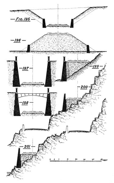
The excavation of a cutting may be greatly reduced in quantity by introducing low retaining walls, as in Fig. 195, and the saving in the material to be removed will be all the more important in those cases where cutting is in excess of embankment.
The amount of filling for an embankment and the land on which it has to be formed may both be considerably diminished by building a low retaining wall, say 6 or 7 feet high, at the foot of the slope, as shown in Fig. 196. Such a retaining wall makes a most efficient fence and well defined boundary of property.
The policy of adopting low retaining walls in cases like the above will depend mainly upon the cost of building materials as compared with the cost of earthwork and land.
Where land is very valuable, and where residential property, streets, or roads must be interfered with as little as possible, the retaining walls may have to be carried up to the level of the original surface of the ground, as in Fig. 197, which is shown as for a cutting 25 feet deep. The walls may be built of masonry, brickwork, or concrete, or a combination of them, and the dimensions or thickness will depend upon the description of material to be supported. Weeping holes, or small pipe drains, should be formed in the walls, a little above formation level, to take away any water which may collect at the back.
Where the cutting is through soft, wet, treacherous clay, liable to slip or expand, it may be necessary to insert arched thrust girders extending from side to side, as in Fig. 198, so that the outward pressure against the one wall may counteract against the outward pressure of the other. The thrust girders should be placed at from 10 to 15 feet centres, and be well braced together in plan to enable them the better to resist any tendency of bulging out of the walls.
A similar arrangement of high retaining wall may be introduced in embankment to lessen the encroachment on streets or public roads, as shown in Fig. 199.
In making a railway through thickly populated towns, it is generally preferable to construct the line on arches rather than on earthwork filling between two high retaining walls. The numerous openings are available for future streets, or means of communication from one side to the other, and the arches themselves can be profitably utilized for stables, stores, offices, and workshops.
Fig. 200 shows a narrow rocky pass with deep rapid river on the one hand and high cliffs on the other, the only available ledge being already occupied by a public highway. By building a retaining wall, as indicated on the sketch, and excavating a little out of the cliff, space may be obtained for a line of railway; or the arrangement may have to be reversed, and the retaining wall for the railway built along the margin of the river, as in Fig. 201.
In both the cases, Figs. 200 and 201, not only must there be a number of weeping holes left in the lower part of the wall, but there must be sufficient well-built drains and culverts under the filling and through the wall to carry away all ordinary or flood water coming down from the cliffs and hills above. Where a retaining wall is built along the margin of a river, the lower portion, which will be in contact with the water when the river is full, should be constructed of selected large heavy stones to withstand the scouring action of the water, and any brushwood or floating timber which may be brought down by flood water.
Where retaining walls are built to support wet clay, or in embanked places on wet side-lying ground, the efficiency of the work will be much increased by constructing a layer, two or three feet in thickness, of dry, flat, bedded stones carefully hand-laid, from the foundation to the top of the wall, as shown in Fig. 199.
These dry stones form a continuous vertical drain to take away water from any part of the earthwork down to the outlets left in the lower portion of the wall.
The building of retaining walls entirely of dry stone is very questionable economy, and entails a constant expenditure in maintenance and renewal. The working out of one stone loosens the surrounding portion of the wall, and if not at once repaired, a length of the wall will fall down, bringing with it a large quantity of the earthwork.
If readily obtained, large heavy stones should be selected for the coping of retaining walls, so as to minimize as much as possible the chance of their disturbance or displacement. Where lighter stones have to be used, or bricks laid on edge, they should be bedded and pointed in cement.
In many places it is necessary to form wide and massive foundations of concrete on which to build the retaining wall; and in some cases of soft, treacherous ground, timber piling may be necessary.
Tunnels.—It would be difficult to assign a date to the first examples of subterranean works constructed for utilitarian purposes. Nature had furnished so many grand specimens of caves, grottoes, and underground passages formed in the solid rock, that man soon grasped the principle, and essayed to carry out similar works on his own account. The early attempts would probably be limited to forming places of shelter, storage or security. Advantage would be taken of those rocks which from their locality, accessibility, and compactness of material, promised favourable results. The appliances being few and primitive, the work of construction would be laborious and slow. So long, however, as the workers restricted their operations to the solid rock, they had merely to contend against the hardness of the material, as the opening or passage-way, once made, required no further support or attention; but as the wave of progress swept onward, man was compelled to deviate from the lines originally followed by nature, and had to form his subterranean pathway through softer material, where the workings required substantial support. The search for minerals of various kinds led to the driving of long headings or galleries underground, and as these had frequently to penetrate through strata of a soft and yielding character, strong timber framework had to be introduced to afford stability to the works, and safety to the workers. For ordinary mining operations, strong rough timber supports may meet all requirements, and may last until the heading is worked out and abandoned; but for subterranean passages or tunnels which are intended to form permanent means of communication, the strongest and most durable materials must be used to protect the interior as far as possible from deterioration or decay. Heavy timbering might be sufficient for mere temporary purposes, but substantial masonry or brickwork side walls and arching became necessary for permanent work in those portions where the tunnel required artificial support.
The first tunnels of any importance were most probably those constructed for canal purposes. Many of them were of considerable magnitude, and in some instances were from two to three miles in length. They were substantially lined with masonry or brickwork at all places where the tunnel passed through soft material or loose rock, and from the solid nature of the work, and the many years they have been in existence, they thoroughly testify to the ability of the constructors.
The introduction of railways involved the making of a large number of tunnels, perhaps more so in the beginning, when it was thought that the use of the locomotive would be confined to very moderate gradients, and when engineers hesitated to adopt the steeper inclines and sharper curves which form the practice of modern times. Another element of consideration also consisted in the fact that the first railways were designed to connect the most populous and busiest districts, where the prospects of heavy traffic would appear to warrant a large outlay for works of construction. As the system spread and railways extended further away from the important centres, the probabilities of traffic would become less promising, and efforts would be made to keep down cost of construction, and avoid tunnel work as much as possible.
It is not easy to define where cutting should end and tunnelling begin. There is no practical difficulty in making a cutting 50, 60, or 70 feet deep, with slopes to suit the material excavated, and the estimated cost per yard forward may even compare favourably with the cost of average tunnel-work. But there are other questions which must be kept in view—the time required to form the cutting, the space to be obtained on which to deposit the enormous quantity of excavated material, and the probable difficulty in obtaining the large area of land necessary for the cutting.
Before deciding the actual position of a tunnel, both as to line and level, it is necessary to obtain the most reliable information possible regarding the strata through which it has to pass. In addition to the geological indications on the surface and in the locality, borings should be made, and trial holes or shafts sunk along the proposed centre line of the work, and from these an approximately accurate longitudinal section can be laid down on paper, showing the respective layers of material to be cut through, and the angle at which they lie. With these particulars before him, the engineer may, in some cases, consider it more prudent to change the position of the tunnel in preference to incurring specially difficult or tedious work in dealing with some recognized unfavourable material. Occasionally the route may be slightly varied and better material obtained, but very frequently there is little to be gained except by a wide deviation from the original line.
Solid rock, except for the slow progress, is perhaps the most favourable material for tunnelling, as the timbering, side walling, and arching can be almost, if not entirely, dispensed with.
Loose rock, although more readily removed, necessitates strong timbering to prevent large masses breaking away and falling into the tunnel.
Some clays are very compact and tenacious, and will stand well with moderate timbering, but even these should not be left long before following up with the side walls and arching.
Many clays give much trouble by expanding, or swelling out, when the excavation penetrates the layer, and although extra strong timbering may be used, and be placed closer together, the logs and planks are frequently bulged out and broken by the action of the clay. Specially strong supports are required for this description of clay, and extra thickness of material in the permanent work of side walls and arching.
Solid unbroken beds of chalk are not difficult to cut through: the material is easy to work, and the excavation will stand with ordinary timbering; but where the chalk is broken and intersected with deep pockets of gravel and sand, the operations are very much impeded. The loose material, once set free by cutting through the confining barrier of chalk, will quickly fall into and fill up the excavation if not held back by strong timbering. Side walls and arching are generally necessary for tunnels through chalk.
Soft wet clay, quicksands, or other strata having springs of water percolating through them, are serious obstacles in the way of expeditious tunnelling. No sooner is one cube yard of this soft material removed than another slides down, or is washed down, to take its place. When once the excavation taps the water-bearing strata, large volumes of water will find their way into the workings, and must be conveyed away to the mouth of the tunnel, or pumped up through the nearest shaft. The timbering of the sides and roof through this description of working is very tedious, and attended also with a considerable amount of risk. The absence of really solid ground on which to place or shore up the supports, taxes the skill of the excavators, and very often, when a short length has been made apparently secure, it will come down with a run, compelling all hands to beat a hasty retreat. The permanent lining through such treacherous material should follow the excavation very closely, and special care should be exercised in building the walls, arching and invert.
In the excavation through stratified rocks it is necessary to note carefully the lie of the strata, whether horizontal, vertical, or shelving, as with each one the excavators are exposed to risks, against which every precaution should be taken. A large horizontal slab of solid-looking rock will suddenly break and fall down without any warning. A heavy mass from a vertical layer, perhaps unkeyed, or loosened, by an adjacent blasting operation, drops down when least expected; and pieces from the high side of the shelving layers detach themselves and slide into the working in a most unaccountable manner.
No attempt should be made to carry a tunnel through material which has been disturbed or at all affected by any natural slip or cleavage, as although the strata may be hard and compact in themselves, they have really no solid or fixed foundation. The sliding away, once initiated, is certain to continue, and, accelerated by the tunnelling operations, will most likely, sooner or later, crush in the tunnel and sweep away every vestige of the work. Amongst the great mountain ranges these natural disturbances are by no means rare, and it will be wiser to keep away from their locality, even at the expense of a longer tunnel. Unfortunately, instances are on record of tunnels made, or in course of construction, through hillsides which had already commenced to slide away from the more solid rock, and the ultimate results were a further sliding away and total destruction of the work.
The lower slopes and outlying portions of high mountains are the most exposed to these natural slips, and they should be most carefully studied before commencing any tunnelling operations through them.
To facilitate drainage, it is essential that a railway tunnel should be laid down with a gradient or gradients falling in the direction of one or both ends of the tunnel. In nearly all tunnels a considerable amount of water finds its way in through the weeping-holes left for that purpose in the side walls, and must be carried away in suitable drains. If the quantity of water be small, ordinary water-tables, one on each side, may be sufficient; but for large volumes of water it will be necessary to build substantial side-drains, or an ample culvert below the level of the rails.
The gradients in a tunnel should be moderate, and not by any means excessive, or likely to tax the hauling powers of the locomotives. When an engine is working nearly to the utmost of its power on a steep tunnel incline, and the speed has become very slow, the exhaust vapours or gases from the funnel strike the arching with great force, and are deflected down on to the footplate in such dense volumes as to almost suffocate the driver and fireman. The writer will never forget two or three trying experiences in foreign tunnels, when he and the engine-staff were compelled to leave the footplate and climb forward to the front of the funnel, leaving the engine to work its way alone. Except for very short tunnels it is wiser to have easy inclines, and to restrict the steep gradients to the open line, where the very slow travelling, or even the coming to a stand from “slipping,” may not produce unpleasant or alarming consequences.
In tunnels of any length it is usual, where possible, to construct shafts extending from the surface of the ground overhead down to the tunnel below. These shafts serve the double purpose of enabling the excavation to be carried on at an increased number of faces, and act as permanent ventilators after completion. In some cases the shafts are sunk exactly over the centre line of the tunnel, in others a few yards away from the centre line. The latter arrangement, if not quite so convenient for hoisting material while carrying on the excavations, has certainly the great after advantage that anything falling or maliciously thrown down the shaft cannot strike a passing train. The short side-gallery, or space between the tunnel and the shaft, provides a good refuge for workmen employed in repairs, and a convenient site for storing a few materials advisable to keep on hand.
Occasionally favourable opportunities present themselves for making horizontal shafts. For a portion of its length the tunnel may be located at no very great distance from the precipitous sides of some deep mountain ravine, or run near to the cliffs on the sea-coast, and advantage can be taken to drive a lateral heading or gallery through which the material from the tunnel excavation may be conveyed and thrown out into the gorge or seashore below.
In many cases the surface of the ground rises so abruptly from the faces of the tunnel and ascends to so great a height, that shafts of any kind are entirely out of the question, and the whole of the work must be carried on from the two ends. The rate of progress is consequently much slower, and the ventilation more difficult. In a shaftless tunnel of considerable length, and with a frequent train service, the question of providing suitable appliances for promoting artificial ventilation is of the utmost importance.
When the centre line of the tunnel has been accurately set out on the ground, and the levels of the different parts of the work decided, the construction of the shafts and the driving of the headings can be commenced. Working shafts intended to serve for permanent ventilation are generally made nine or ten feet or more in diameter, and are usually lined with substantial brickwork or masonry. When the well-like excavation has been carried down a few yards, or as far as it can be taken without the risk of the earth falling in upon the sinkers, a strong curb of hard wood or iron of the same diameter as the finished shaft is laid down perfectly level and to exact position, and on this curb the ring or lining of brickwork or masonry is built up to the level of the ground. The first length finished, the excavation downwards is resumed, and the interior lining continued, either by allowing the first length to slide down as the material below is gradually removed, and building further lining on the top, or by excavating and propping up the curbing with strong timbers below. When working to the latter method, stout wooden props of convenient length, stepped on to sole-pieces, are adjusted to the under side of the wooden curb above, the material is then removed for the thickness of the brickwork or masonry, and another curb accurately set to level and position; on this is built a length of lining up to the first curb.
This work of under-building or under-pinning must be carried out with great care and in segments; no props must be removed until the curb immediately above is well supported by the new lining, and the inside of the lining must be watched and tested to prevent any tilting. All spaces at the back of the work must be filled in and well packed with hard dry material. As the shaft is continued downwards the mode of working may have to be varied; different descriptions of material may be encountered, and blasting, shoring, and pumping may each in turn be necessary.
When down to the full depth, the lower length of the shaft will have to be securely supported by strong timbers, until it can be properly built into and incorporated with the arching of the tunnel or side gallery.
The completion of the shaft enables the workings to be commenced on each side, the excavated material can be hoisted to the surface, and building material lowered down. When the tunnel works are finally finished, the lining of the shaft should be carried up until it is 15 or 20 feet above the level of the surface of the ground, and a dome-shaped iron grating placed on the top as a protection against stones or other articles which malicious persons might attempt to throw down the shaft.
Some shafts are only intended for the temporary purpose of lifting the excavations from below, or lowering building materials down, and when the work is completed they are filled in again and closed. These service shafts are generally made square in section, and are merely lined with wood. Strong vertical timbers are placed at the four corners, to which horizontal double cross-pieces are bolted, thick planking being placed vertically at the back of these cross-pieces to support the sides of the excavation.
The heading of a tunnel is a narrow passage or gallery cut through from end to end of the works in the direction of the centre line. Where there are shafts, the cutting of the heading can be pushed on from several points, and be completed much more rapidly than when the working is restricted to the two ends. Headings are usually made just sufficiently large for the miners to work, say about 5 feet 6 inches high by about 3 feet wide, the object being rather to expedite the driving of the driftway than to remove large masses of material. They must be set out with great accuracy, and be constantly checked as the driving is in progress. When completed from end to end, the centre line can be checked throughout, and the course actually taken compared with the course intended. If there has been much variation in the narrow pioneer pathway, either in line or level, the amount of the divergence must be rectified when ranging the final centre line for the full-size excavation.
Tunnels cannot always be delayed until the heading is cut through for the entire length. In many cases the heading, the full-size excavation, and the permanent lining have all to be carried on at the same time, but as the work of the heading is smaller in extent, that portion of the operations can usually be kept well in advance of the others. The critical moment arrives when the headings from opposite directions meet, as any deviation or want of coincidence must be adjusted in the portion of the tunnel still remaining to be opened out to full size. Some tunnels of moderate length have been constructed without any heading at all, the excavation being taken out to the full dimensions from the commencement.
The heading of a tunnel assists not only in the correct alignment of the work, but furnishes at the same time an accurate knowledge of the strata passed through. It is also of service for ventilation, communication, and drainage.
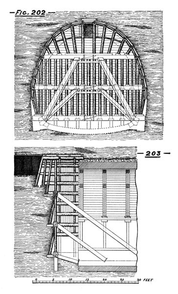
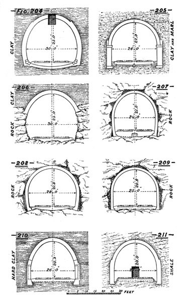
In some cases the heading is driven at the bottom of the tunnel section, as in Fig. 211, and in others at the top, as in Figs. 202 and 204. Many of the earlier tunnels were constructed on the former system, while of late years the latter method has been very largely adopted. The bottom heading may perhaps in some instances be more efficacious for drainage, but it is very liable to be frequently choked up when taking out the excavation to the full size, and the lower surface is much cut up by the movement and conveyance of materials. Another disadvantage arises from the necessity of removing such a large amount of the cutting approaching the tunnel entrance before a beginning can be made to the bottom heading. The top heading has the advantage that it requires less removal of open cutting previous to its commencement, and, being high up in position, there is less chance of its being stopped up by falling material, the finished excavations being carried out on the sides and below the heading.
Where the headings are cut through solid rock, stiff shale, or compact chalk, little or no supports are necessary, but where they pass through clay or loose material, timbering will be required for sides, roof, and floor. Rough round poles, about 6 inches in diameter, are generally used for verticals, and are firmly secured to transverse sole-pieces, and on the top of these verticals strong transverse top-sills are fastened by means of rough tenons or checks. Strong boards are inserted at the back of this framework to keep the earth from falling into the working. The distance apart of the verticals will depend upon the description of material excavated; in very soft places they will have to be placed very close together, but where fairly sound and tenacious they may be placed at about 3-foot centres. The excavated material must be conveyed away to the entrance of the heading in small hand-trucks running on planks or light rails.
The widening out of the excavation to the full size will be a repetition on a large scale of the work carried out in the heading, with the difference that, the exposed surfaces being of so much greater extent, extra care and precautions must be taken with the framework and shoring of the timbering.
The form and arrangement of the timbering, as well as the number, sizes, and positions of the pieces, must be determined by the material of the excavation and the contour line of the finished arching or lining. The framework, which would be sufficient to support ordinary soft material, must be largely augmented both in quantity and scantling to meet the requirements for wet treacherous clay.
Figs. 202 and 203 give end view and longitudinal section of timber framework frequently adopted for average tunnel work. The positions of the different pieces will explain themselves and the duty they have to perform. The main struts, or raking pieces, which have to sustain great pressure, may be shored against the finished lengths of masonry or brickwork. The timbering of the sides can be removed as the lining proceeds, but in many cases the round logs and boards near the crown cannot be withdrawn, and have to be left in the work, the space between the top of the arching and under side of the boards being firmly packed with brickwork, masonry, or dry rubble stonework.
As the tunnel lining is generally carried forward in short lengths, following up the main excavations, the centering for the arching should be of such description that it can be readily transferred or moved forward as the work proceeds. The form of the centering, and the spacing of its upright supports, must admit of sufficient width for one or more lines of rails for the waggons required to remove the excavated débris and convey the building materials used in the lining.
Picks, bars, and shovels are the tools used in the excavation of the softer material and loose disintegrated rock, but for the hard rock, blasting will be necessary. The tunnel opening being comparatively small, only moderate blasting charges can be used with safety, and these must be placed so as to break up the rock-bed in a suitable manner for working, and without shaking or damaging the already completed excavation. Ordinary hand-drills, or jumpers, may be used for forming the charge holes, a number of them being at work at the same time, and the charges fired very closely one after the other. As the blasting operations necessitate the retiring of the miners to a considerable distance, out of the way of flying fragments, and the remaining away until the foul air has been dispelled, it is advisable to fire off several charges about the same time, and thus minimize as much as possible the stoppage to the drilling and clearing away the loosened material.
Mechanical drills, worked by compressed air or other motive-power, are now very extensively used where the rock is solid and continuous. They are much more expeditious than the hand drills, but they are costly in their installation, and also in their working and maintenance.
In some tunnels, where the material has been firm and dry, the upper portion of the excavation has been first removed, and the masonry and brickwork lining built in position down to about the springing of the arch, the remainder of the excavation being afterwards taken out, and the side walls built by means of shoring and underpinning.
In other tunnels the complete section has been excavated and timbered, and the work of building commenced from the foundation of the side walls. A strong continuous invert from side wall to side wall is necessary where passing through soft swelling clay or loose strata intersected with small streams of water. Where the material is very solid and dry, it is not necessary to introduce inverts, but the foundations of the side walls should be laid at such a depth below rail-level as not to be affected by drain-water running through the tunnel.
The side walls and arching may be either of masonry or brickwork, but should be of the best description, especially for the facework. For brick arching only the best hard-burnt bricks should be used, and the inner or exposed ring should consist of selected hard fire-bricks to withstand the heat and gases escaping from the funnels of the locomotives. The thickness of the side walls and arching will depend upon the description of material to be supported. In some places a comparative thin lining may be sufficient, while in others extra thickness must be given to resist the great pressure exerted by expanding clay and loose wet strata.
Weeping-holes, or small drain-pipes, placed low down must be left in the side walls every three or four yards, or closer in very wet places, to allow the water collected at the back of the walls to escape into the side drains of tunnel. In building the arch portion every effort should be made to have close solid work without any open joints or spaces through which the water may run, and the crown of the arch and a few feet down on each side should be coated with cement or asphalte to lead all water away from the top to the sides. Water dripping from the under side of the arch on to the line is a great destructor of the permanent way materials, especially the fastenings; and bolts, nuts, fish-plates, and spikes placed in a wet dripping tunnel will not last half the time they would out in the open line, where they would have the sun and wind to dry them.
Small arched recesses or niches should be formed in the side walls at convenient distances to serve as refuges for platelayers or others working in the tunnels.
It is most essential that the space between the masonry and brickwork lining and the facework of the excavation should be carefully filled in and hard packed, so as to prevent the possibility of pieces of rock or other material falling on to the top of the arch. The neglect of this precaution may lead to a casualty years after the tunnel has been completed.
It would be impossible to over-rate the importance of a constant faithful supervision of the building of the lining, especially the arching. The work has to be carried on by workmen in cramped positions, with imperfect light, and surrounded by all kinds of obstacles and inconveniences, and unless a detailed inspection be rigidly maintained, a carelessness in the selection of the materials, and a laxity in the workmanship, will be the inevitable result.
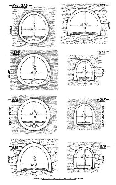
Figs. 204 to 219 are sections of tunnels which have been constructed for double and single line railways. The sections give the normal form and dimensions adopted in each case, although there may have been many portions of the work where unfavourable or treacherous material necessitated an increase in the thickness of the side walls, or of the arching, or of both. The types vary in accordance with the opinions of the designers as to the most suitable section for the purpose, and range from the comparatively thin lining and vertical side walls shown on Fig. 207, to the almost circular form and very thick lining shown on Fig. 216. The latter is the section which experience has proved to be the best to sustain the enormous all-round pressure exerted by certain descriptions of swelling clay.
Careful judgment will be required to decide which parts of a rock tunnel may be left unlined. The apparently solid-looking portions are oftentimes deceptive, and numbers of instances are on record of large pieces of rock falling down in tunnels which for many years had been considered as thoroughly secure. Where there is any doubt it is better and safer to put in a lining, even if only to the extent of an arching springing from side walls of solid rock, as shown on Fig. 206. A moderate additional expenditure at the time of construction may prevent a serious catastrophe afterwards.
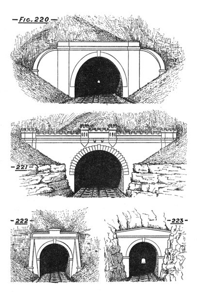
The faces or entrances to tunnels may be constructed with curved wing walls, as in Fig. 220, or with straight wing walls, as in Figs. 221, 222, and 223. Where the approach cutting is in rock, the latter form is generally adopted.
It would be misleading to put down any average price for tunnel-work. So much depends upon the locality, the description of material to be excavated, the cost of masonry or brickwork, and the cost of labour. Added to these come the unforeseen troubles of slips and water-laden strata, creating difficulties which baffle the miners for a time, and add enormously to the expenditure. Some tunnels for double line have been constructed in good ground, and under favourable circumstances as to building materials and labour, for as low as £32 per lineal yard; while others, carried out under adverse conditions, have cost as much as £150 per lineal yard. A medium somewhere between the two should represent the cost of tunnel-work through ground which does not present any special difficulty. At the same time it must be borne in mind that simple tunnelling which can be done in one locality for £50 or £60 per lineal yard, would be increased 20, 30, or 40 per cent. in another, where building material for the lining is scarce and expensive.
Tunnel-work abroad will generally cost more than the same work at home. The native labourers may perhaps be procured at low rates, but the skilled workmen must be brought from a distance, and will obtain high wages.
Another form of tunnel-work, generally termed the covered-way system, is frequently adopted in towns and places where land and space are very valuable. This method consists in the excavating and removing of earthwork to admit of the building of the side walls and arching of a suitable tunnel-way, and then filling in over the top to a depth of three or four feet, or up to the level of the original surface of the ground. This work may be carried out by either removing the entire width of the earthwork before the commencement of any building operations, or by first forming two deep, well-shored trenches, in which to build the side walls up to about arch-springing. In bad ground the latter arrangement has the advantage, as the shoring and strutting to hold up the sliding material is limited to the widths of the two narrow trenches, and the centre block of earthwork is left untouched as a support to the strutting. When the side walls have been built sufficiently high the upper portion of the centre block of earthwork can be removed to allow of the erection of centering and building of the arching, and afterwards the remaining portion of earthwork can be removed at convenience. In this manner a tunnel-way may be constructed under streets, gardens, and even under buildings. Being nearly all done in the open, the work is more under control than in an ordinary tunnel, but it is usually very costly. Temporary or diverted roads must be arranged; the excavated material must generally all be removed by carts, sometimes to long distances; and provision must be made for diverting the network of sewers, gas, and water pipes which are intercepted along the route.
Fig. 224 is a sketch of covered-way with brick arching. Fig. 225 illustrates another type where cast-iron girders and jack-arches of brickwork were introduced on account of the small headway. In soft yielding clay it is necessary to construct strong inverts, as indicated in the sketches. Recesses for the platelayers should be provided every ten or fifteen yards.
The above systems of covered-way were largely adopted in the construction of the underground portions of the Metropolitan Railway and District Railways in and around London.
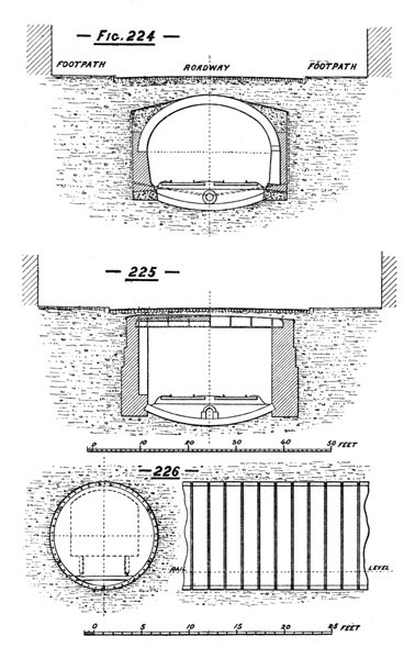
In addition to the ordinary type of tunnel formed by first excavating the material and then lining the opening with brickwork or masonry, tunnels of moderate size have been constructed of cast-iron tubes, similar in section to Fig. 226. The tubes were cast in short segments, bolted together inside, the outer circumference, or surface in contact with the earth or clay, being left free from projections of any kind. By making the segments with bolt-holes exact to template, they were readily fitted together in the work, and a thin layer of suitable packing material placed between the bolting-flanges sufficed to render the tubes water-tight. The tunnelling was carried on by means of a short length of slightly larger tube, or cap, made of plate-iron or steel, which fitted over the leading end of the main tube. The front end of this cap was made very strong, and provided with doors through which the miners could work. A series of hydraulic presses attached to the cap were brought to bear on the bolting-flange of the last completed ring, and as the excavated matter was removed by the miners from the front the cap was forced forward by the hydraulic presses, and another ring of cast-iron segments inserted. On the City and South London Railway, constructed on the above system, the small annular space formed round the cast-iron tube by the operation of the sliding cap was filled in with cement grouting by means of an ingenious machine designed for the purpose.
Large tunnels under rivers or tidal estuaries must each be dealt with according to the particular circumstances of depth below stream-bed, material to be cut through, length of tunnel, and gradient. The chief obstacle to be contended against in so much of the river tunnel-work is the large volume of water which pours into the workings through fissures in rock or seams of gravel and sand, necessitating the constant use of most powerful pumps. In ordinary land tunnels the gradients are generally laid out to fall towards one or both entrances, and any water finding its way into the excavations may be led away to the entrances by drains or pipes. On the other hand, in a river tunnel the gradients generally fall away from the entrances down towards the centre of the river, and all water coming in must be pumped out and raised up to at least the level of the river. In places where the water comes streaming in from many points, any failure or stoppage of the pumps would place the lives of the miners, and the security of the work itself, in great jeopardy. Iron shields, or protection chambers for the miners advancing the excavation, have been used with great success in carrying on work through loose wet strata which appeared to defy all other means of progress. Solid rock, chalk, or compact clay, may present no difficulty so far as they go, but a continued dip in the gradient, or a line of fault, may suddenly change the entire course of operations, and require the immediate use of the most powerful pumping machinery and protective appliances. The special features of each case will demand special precautions, and the judgment and inventive powers of the engineer will be severely tested in coping with the difficulties with which he is surrounded.
[Contents]