PART TWO—VEHICLE MAINTENANCE INSTRUCTIONS (continued 3)
Reading edition
(7) Attach brake control cable end to foot pedal stud.
c. Remove Rear Chain Guard.
(1) Remove cap screw which secures rear chain oil pipe clamp, and provides mounting for front end of chain guard on transmission sprocket cover. Remove chain guard.
(2) Remove chain guard from rear mounting by pushing the guard back so that stud (with washers and spring) slips out of mounting clip notch.
d. Install Rear Chain Guard.
(1) Locate rear chain guard in position for mounting. Spread the large washer on the rear stud to engage clip notch. Push guard forward until front end hole lines up with chain oiler pipe clamp, then install cap screw and washer, securing guard and clip to sprocket cover.
103. CARRIERS.
a. Remove Ammunition Box Carrier.
(1) Remove nut and screw which secures carrier bracket to front mudguard.
(2) Remove nut and lock washer from rocker plate rear stud. This frees lower end of carrier.
(3) Remove nut, washer, cable clip, and plain washer from rigid fork stud. Remove carrier and box.
b. Install Ammunition Box Carrier.
(1) Locate hole in lower end of bracket on rocker plate rear stud. Attach upper end of bracket to rigid fork stud. Replace lock washers and nuts. Tighten nuts.
(2) Attach carrier bracket to front mudguard with screw, washer, and nut. Tighten nut.
c. Remove and Install Scabbard Carrier. The procedure for removing and installing scabbard carrier is the same as outlined for ammunition box carrier, except that scabbard carrier is on left side of vehicle. Follow procedure outlined under steps a and b above.
d. Remove Luggage Carrier.
(1) Loosen straps of both saddlebags, and remove saddlebags from keyhole notches in luggage carrier side plates. Remove nuts from right and left side mounting studs, which secure luggage carrier to frame clips. Deflate rear wheel tire so that a piece of wood or suitable object can be used to depress top part of tire under mudguard, to provide clearance, and access to the three nuts which secure screws for luggage carrier mudguard mounting. NOTE: If rear wheel is removed, mounting screws are accessible.
(2) Remove the three luggage carrier center mounting screws. Remove luggage carrier from vehicle.
e. Install Luggage Carrier.
(1) Mount luggage carrier on frame clip studs. Install washers and nuts. With rear tire deflated and depressed for clearance under mudguard, install the three screws, lock washers, and nuts for carrier‐mudguard mounting. NOTE: If rear wheel is removed, mounting screws are accessible.
(2) Tighten frame stud nuts to secure both sides of carrier.
(3) Attach saddlebags and securely strap to frame stays.
(4) Inflate tire to 20 pounds.
104. MUDGUARDS.
a. Remove Front Mudguard.
(1) Remove front wheel (par. 125).
(2) Remove instrument panel cover (par. 119), disconnect front mudguard blackout marker light wire at switch. Pull wire out, free from tanks.
(3) Remove the two screws and nuts from rigid fork and mudguard mounting. Remove the two screws and nuts securing lamp bracket to mudguard.
(4) Remove bolt and nut which secure ammunition box carrier to mudguard.
(5) Remove bolt and nut which secure gun scabbard carrier to mudguard.
(6) Remove nuts from fork left rocker plate stud. These nuts secure ammunition box lower bracket, and mudguard stay clip. Remove nuts from fork right rocker plate stud. These nuts secure gun scabbard carrier lower bracket, and mudguard stay clip.
(7) Pull carrier brackets off rocker plate studs. Remove mudguard brace clip locks from slots in clips so that mudguard can be dropped. When removing mudguard from vehicle, take care not to break and/or damage blackout light wire.
b. Install Front Mudguard.
(1) Locate mudguard in mounting position. Engage slots in stay clips on rocker plate studs, installing the special locks in the clip slots. NOTE: Brace clip locks are made for right and left side installation. Secure both clip locks with stud nuts.
(2) Attach ends of ammunition and scabbard carriers to rocker plate studs. Secure with lock washers and nuts.
(3) Mount mudguard to rigid fork bracket. Tighten the two screws, washers, and nuts.
(4) Attach lower end of headlight bracket to mudguard with two bolts, washers, and nuts.
(5) Attach ammunition box carrier bracket to mudguard. Tighten bolt, washer, and nut.
(6) Attach gun scabbard carrier bracket to mudguard. Tighten bolt, washer, and nut.
(7) Reinstall front wheel and brake assembly (par. 125).
(8) Connect mudguard blackout light wire to switch terminal. Refer to wiring diagram, figure 73.
(9) Install instrument panel cover (par. 119).
c. Remove Rear Mudguard.
(1) Support vehicle on rear stand. Remove rear wheel (par. 127).
(2) Remove luggage carrier (par. 103).
(3) Remove rear chain guard (par. 102).
(4) Remove the two U‐bolt nuts which mount safety guard at upper frame bracket. Then pull safety guard away from studs and remove studs from frame bracket, freeing mudguard at this point. NOTE: These two studs screw into a “plate” nut.
(5) Remove bolt and nut which secure battery box left‐side bracket to mudguard.
(6) Remove bolt and nut which secure battery box right‐side bracket. This bolt also secures lower tool box bracket and speedometer cable clip to mudguard.
(7) Remove nut and washers from bolt which secures lower end of mudguard to frame (behind transmission).
(8) Remove taillight connector plugs from sockets and remove cable from mudguard spring clips.
(9) Remove nuts from studs which secure right‐ and left‐side mudguard brace clips to frame axle clips. Mudguard can now be removed from vehicle.
d. Install Rear Mudguard.
(1) Locate mudguard in position for mounting. Install the two studs, washers, and nuts which secure right‐ and left‐side brace clips to frame axle clips. NOTE: If brake side cover interferes with locating nut on right side, loosen the brake sleeve nut and push brake side cover assembly inward for clearance. Be sure to retighten brake sleeve nut.
(2) Attach front lower end of mudguard. Install flat washer, lock washer, and nut on bolt to secure lower end of mudguard to frame (in back of transmission).
(3) Install the two studs which mount mudguard and upper battery box bracket on frame bracket. These two studs screw into a plate nut located underneath the battery box bracket. Removing the battery box cover will give more access to plate nut in this step. Install battery box cover if it is removed for this job.
(4) Attach rear safety guard to the two frame bracket studs. Install washers and nuts. Securely tighten nuts and tighten U‐bolt nuts, which secure ends of safety guard to frame stays.
(5) Attach battery box bracket to mudguard bracket. Install bolt, washer, and nut which secure battery box right‐side bracket, tool box bracket lower end, and speedometer cable clip to mudguard bracket. Bolt is inserted from front side, head toward engine. NOTE: Speedometer cable clip is under head of bolt.
(6) Attach left‐side mudguard bracket and battery box bracket. Install bolt, washer, and nut which secure battery box left‐side bracket to mudguard bracket. Bolt is inserted from front side, head toward engine.
(7) Install rear chain guard (par. 102).
(8) Locate and retain taillight cable in mudguard spring clips. Attach connector plugs to taillights (wiring diagram, fig. 73).
(9) Install luggage carrier (par. 103).
(10) Install rear wheel (par. 127).
(11) Securely tighten all bolts and nuts.
105. BATTERY BOX.
a. Remove Battery Box.
(1) Remove battery (par. 113).
(2) To remove rear brake rod, disconnect clevis from brake lever, and free front end of rod at brake shaft bell crank.
(3) Remove rear chain guard (par. 102).
(4) Remove tool box and bracket in one piece (par. 106).
(5) Remove nut and bolt securing left side lower battery box mounting to mudguard bracket. Remove nut and bolt securing battery front mounting to frame saddle post tube bracket.
(6) Remove the two nuts securing rear safety guard center connection to mounting studs. Unscrew mounting studs to free the plate nut which clamps the battery box bracket to frame cross member.
(7) Remove battery box from right side of vehicle.
b. Install Battery Box. Locate battery box in vehicle from left side and secure upper rear mounting bracket with the two frame cross member studs and the plate nut. Install washers and nuts which secure safety guard to these same two studs.
(1) Install bolt to secure battery box front mounting to frame tube. Make sure that bolt passes through frame tube bracket from left side, and that large plain washer bears against battery box front bracket (bracket has open end). Tighten nut to secure box bracket to frame tube bracket.
(2) Install tool box and bracket (par. 106).
(3) Install bolt, washer, and nut which secure battery box left‐side mounting to mudguard. Insert bolt from the front.
(4) Install rear chain guard (par. 102).
(5) Connect rear brake rod end to bell crank fitting. Attach clevis to brake operating lever, installing plain washer, clevis pin, and cotter pin.
(6) Install battery (par. 113).
106. TOOL BOX.
a. General. When tool box only is to be removed and/or installed, it is a simple matter to open box and remove and/or install the three large screws. Gear‐toothed lock washers and large recessed washers fit under screw heads.
b. Remove Box and Bracket Assembly. Remove bolt and nut which secure tool box upper mounting bracket to frame clip. Lower end of mounting bracket, battery box bracket, and speedometer cable are all secured to the mudguard bracket by the same bolt and nut. Remove speedometer cable from clip and remove bolt and nut, freeing tool box and bracket assembly for removal. NOTE: Removal of rear brake rod will make bracket lower mounting bolt and nut more accessible.
c. Install Box and Bracket Assembly. Locate box and bracket assembly on vehicle and install bolt, washer, and nut at the upper frame clip mounting. To attach bracket lower end to mudguard bracket, place bolt through speedometer cable clip, then through box mounting bracket, battery box bracket, and mudguard bracket, securing assembly with lock washer and nut.
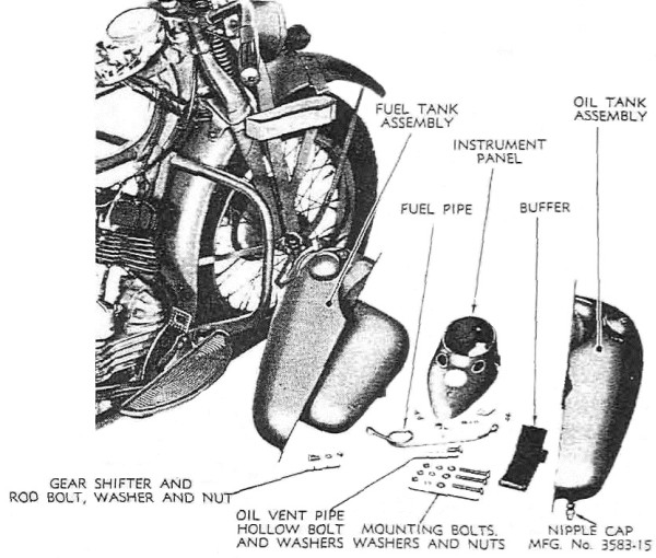
RA PD 310245 Figure 70—Fuel and Oil Tanks Removed
107. TANKS (fig. 70).
a. General. Fuel and oil tanks are separate, fitting together, saddle‐type, in upper frame tubes, and are retained in position with three mounting bolts. Either tank can be removed and/or installed without disturbing line connections of the other tank.
b. Fuel Tank. Fuel tank is located on left side of vehicle and holds slightly over 3 U.S. gallons. It provides mounting for shifter lever and shifter lever guide. Drain is located in forward position on under side of tank.
c. Oil Tank. Oil tank is located on right side of vehicle and holds 1 U.S. gallon. Oil feed pipe, scavenger (return) pipe, and breather pipe connections are on under side of tank. Drain is located in forward position on under side of tank.
d. Remove Fuel Tank.
(1) Disconnect battery negative ground wire at frame connection.
(2) Loosen the two cap screws which secure caution plate and tank top strip.
(3) Remove instrument panel cover (par. 119).
(4) Disconnect gear shifter lever and shifter rod by removing bolt.
(5) Shut off fuel supply. Disconnect fuel pipe at tank union nipple.
(6) Remove nuts, lock washers, and flat washers from the two front (one upper and one lower) mounting bolts, and nut, lock washer, and flat washer from the rear mounting bolt. Leave bolts in place so that oil tank will stay in position after fuel tank is removed. Remove fuel tank from vehicle.
e. Install Fuel Tank.
(1) Position fuel tank on vehicle. Pass the three mounting bolts through tank brackets from right side of vehicle. It will be necessary to pry up on tank top strip in order to slip top edge of tank under strip. Install large flat washers, lock washers, and nuts on mounting bolts and securely tighten the nuts.
(2) Tighten the two cap screws, securing caution plate and tank top strip.
(3) Connect fuel pipe at tank nipple union. Open supply valve.
(4) Install instrument panel cover (par. 119).
(5) Connect gear shifter lever and shifter rod by installing bolt, lock washer, and nut.
(6) Connect battery negative ground wire to frame connection.
(7) After fuel tank has been filled, check pipe connection and drain plug for leaks.
f. Remove Oil Tank.
(1) Disconnect battery negative ground wire at frame connection.
(2) Loosen the two cap screws which secure caution plate and tank top strip.
(3) Remove instrument panel cover (par. 119).
(4) Drain oil from tank by removing drain plug. Use a trough (of cardboard or tin) to keep oil from draining on engine. NOTE: If oil feed pipe nipple cap (manufacturer’s (H–D) No. 3583–15) is available, it can be screwed on to tank nipple, thus eliminating draining of oil.
(5) Disconnect oil feed pipe at rear nipple union.
(6) Disconnect scavenger (return) pipe at nipple union.
(7) Disconnect breather pipe banjo‐type connection by taking out bolt.
(8) Remove nuts, lock washers, and flat washers from the two front (one upper and one lower) mounting bolts, and nut, lock washer, and flat washer from rear mounting bolt. NOTE: To prevent fuel tank from falling out of frame, remove upper front mounting bolt and rear mounting bolt and pass both back through fuel tank mounting brackets from the left side of vehicle. Oil tank can then be removed, and fuel tank will stay in place.
g. Install Oil Tank.
(1) Position oil tank on vehicle. Make sure that composition buffer is in place before installing mounting bolts from right side of vehicle. Pry up on tank top strip in order to slip top edge of tank under strip.
(2) Install large flat washers, lock washers, and nuts on mounting bolts. Securely tighten the nuts.
(3) Tighten the two cap screws securing caution plate and tank top strip.
(4) Connect oil feed pipe to tank nipple. Tank nipple is located at lower rear end of tank.
(5) Connect scavenger (return) pipe to tank nipple. Nipple is located underneath tank, near center.
(6) Connect breather pipe with banjo‐type fitting to tank. Use hollow bolt, making sure flat washers are in place on both sides of banjo fitting and that mounting bolt is tight.
(7) Install instrument panel cover (par. 119).
(8) See that oil tank drain plug and washer are in place, and that the plug is tight.
(9) Connect battery negative ground wire to frame connection.
(10) After filling oil tank, check all pipe fittings for leaks.
108. STANDS.
a. Remove Rear Stand. Remove nuts which secure rear stand mounting bolts. Drift bolts out of frame clip holes, freeing stand.
b. Install Rear Stand. Locate stand in position so that bracket stop is downward and will bear against frame axle clips to support vehicle when stand is in use. See that cupped spring washers are on mounting bolts before attaching stand to frame. Drift mounting bolts into frame axle clips and secure with lock washers and nuts.
c. Remove Jiffy Stand.
(1) Support vehicle on rear stand.
(2) Loosen footboard rear support stud nut. Remove footboard front support rod nut and pull footboard outward to release end of safety guard. Remove extended nut from footboard sidebar front mounting. Remove nut securing upper end of skid plate hanger and sidebar rear mounting (located in center of chain guard cover). Loosen nut and bolt which secure skid plate hanger bracket to skid plate: drop bracket. Disconnect clutch control cable from foot pedal stud to prevent damage to cable end piece. Remove left footboard, clutch foot pedal, and sidebar assembly from support rod ends.
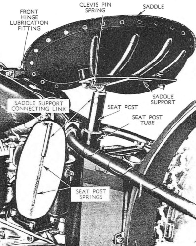
RA PD 310269 Figure 71—Saddle and Suspension
(3) Remove the two nuts from U‐bolt which secure safety guard bracket to frame tube, remove bracket from U‐bolt, and slide safety guard assembly out of support rod.
d. Install Jiffy Stand.
(1) Install safety guard assembly on support rod and secure mounting bracket to frame tube with U‐bolt, washers, and nuts.
(2) Install footboard, clutch foot pedal, and sidebar assembly. Attach skid plate hanger bracket and secure to support rod. Attach clutch control cable end to foot pedal stud, installing plain washer and cotter pin. Install washer and extended nut on end of front support rod. Securely tighten nut. Attach front end of sidebar to end of safety guard by pulling front of footboard outward, alining hole in safety guard end with hole in sidebar, and passing footboard front support stud through both parts, securing with washer and nut. Tighten footboard rear support stud nut.
(3) Return vehicle to operating position.
109. SADDLE POST (fig. 71).
a. Saddle is mounted on saddle bar by means of three mounting bolts and can be shifted forward or backward to provide three positions on saddle bar. Spacer collars can be added and or removed from the two rear mountings to raise or lower rear of saddle to alter riding position. Saddle bar hinges on frame bracket and is clevis‐connected to saddle spring post. Saddle and saddle bar can be lifted upward and forward after releasing spring latch (on left side) from groove in clevis pin end and removing clevis pin from saddle bar.
b. Remove Saddle Spring Post. Support vehicle on rear stand. Raise saddle and saddle bar after removing saddle post clevis pin. Remove bolt and nut from left‐side skid plate bracket and remove nut to free right‐side skid plate bracket at muffler pipe clamp and frame connection. Drop skid plate. Remove saddle spring post clamp nut, which is located underneath frame at bottom end of saddle post frame tube. Saddle spring post assembly can be pulled upward out of frame tube.
c. Install Saddle Spring Post. When saddle spring post assembly is inserted in frame tube, see that flat side machined on post rod end nut registers in flat side of hole in bottom of frame tube. Install and securely tighten saddle spring post clamp nut at bottom end of frame tube. Lift skid plate and secure in position with left‐side bracket bolt, washer, and nut and with right bracket bolt, washer, and nut (this also secures muffler pipe clamp to frame clip). Lower saddle and saddle bar into position. Insert clevis pin from right side and secure with spring latch, making sure that spring is in pin groove.
110. SAFETY GUARDS.
a. Remove Front Safely Guard.
(1) Loosen nuts which secure right and left footboard rear support studs to sidebars. Remove nuts which secure right and left footboard front support studs (and mount ends of safety guard) to sidebars. Pull front end of each footboard outward so that support stud will free end of safety guard. Remove four nuts from the two U‐bolts which mount safety guard upper bracket to frame tube. Remove safety guard.
b. Install Front Safety Guard. Locate safety guard and mount upper bracket to frame tube with the two U‐bolts, washers, and nuts, but do not tighten nuts as yet. Pull front end of right footboard outward, line up hole in safety guard end with hole in sidebar, and pass footboard front support stud through both parts, securing with washer and nut. Follow same procedure to mount left end of safety guard. Tighten U‐bolt nuts securely.
c. Remove Rear Safety Guard. Remove nuts from U‐bolts which mount ends of safety guard to lower frame stays. Remove the two nuts from upper safety guard mounting. After removing U‐bolts, safety guard can be removed from vehicle.
d. Install Rear Safety Guard. Position safety guard on vehicle. Install U‐bolts, washers, and nuts for lower end mounting on frame stays. Do not tighten nuts. Engage upper mounting holes on studs and replace washers and nuts. Tighten all mounting nuts.
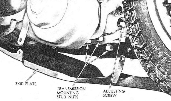
RA PD 310234 Figure 72—Showing Skid Plate Dropped
111. SKID PLATE.
a. Rear end of skid plate must be dropped when removing and or replacing muffler assembly, saddle spring post, transmission, and engine.
b. Drop Skid Plate (fig. 72).
(1) Remove nut from bolt which secures skid plate side mounting bracket to frame clip. This bolt also mounts muffler tube clamp to frame clip.
(2) Remove left side mounting. Remove nut and bolt which secures lower end of hanger bracket to skid plate on left side of vehicle. Drop rear end of skid plate.
c. Install Dropped Skid Plate.
(1) Lift rear end of skid plate into position. Attach right‐side bracket at frame clip bolt. Secure mounting with washer and nut.
(2) Attach lower end of left‐side hanger bracket to skid plate. Install bolt, washer, and nut. Tighten nut.
d. Remove and/or Install Skid Plate.
(1) To remove skid plate from vehicle, follow instructions in step b above; then remove nut and bolt from U‐clamp which secures skid plate to frame bracket, and remove nut and belt from clamp which secures right front end to support rod.
(2) To install skid plate, mount right front end to support rod clamp, and install bolt and nut to secure U‐clamp under frame bracket. Then follow instructions in step c above.
Section XXIII BATTERY, LIGHTING SYSTEM, HORN
Paragraph
Description112
Battery113
Headlights114
Taillights115
Ignition and light switch116
Horn117
Wiring118
112. DESCRIPTION.
a. Lighting system and horn are supplied 6‐volt current from the 22‐ampere‐hour battery. Negative side of battery and system is grounded. Blackout lights and service lights are controlled by the same switch (ignition and light switch) which also controls ignition. Blackout headlight has auxiliary control switch in body. Service headlight upper and lower beam is controlled by toggle switch on left handle bar. Horn is operated by button on left handle bar after ignition and light switch is in “ON” position. Blackout stop light and service stop light are operated by brake foot pedal switch.
113. BATTERY.
a. The 3‐cell, 15‐plate, 6‐volt, 22‐ampere‐hour battery is located in battery box back of frame seat post tube, and is accessible for inspection and or service after removing box cover. Normally charged battery has specific gravity reading of 1.275. Normally discharged battery has specific gravity of 1.150.
b. Check Electrolyte Level (fig. 74).
(1) Raise saddle and bar assembly after releasing and removing swivel pin.
(2) Loosen wing thumb nuts on box top hold‐down studs sufficiently to disengage bracket slots, then lift off box cover.
(3) Remove the three filler plugs. Check and or adjust electrolyte level. See that electrolyte level is 5⁄16 inch above plates. If necessary, bring electrolyte to that level, using clean, drinkable water.
(4) Clean top of battery before installing box cover.
(5) Clean terminals or posts, if corroded. Make sure that the felt washers are on posts and are saturated with engine oil.
c. Remove Battery. Raise saddle and bar assembly. Release and remove swivel pin. Loosen wing thumb nuts on box top hold‐down studs sufficiently to disengage bracket slots, then lift off box cover. Disconnect positive and negative wires from battery terminals. Lift battery upward out of battery box.
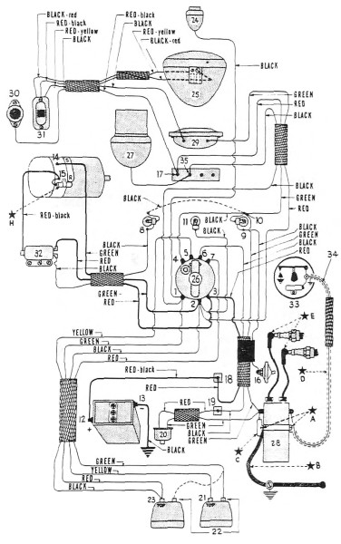
RA PD 310278 Figure 73—Complete Wiring Diagram
1. SWITCH TERMINAL (Three Wires connected)—Black wire from blackout marker light 24; taillight cable green wire from blackout taillight 22; single wire direct from blackout headlight as shown by dotted line in illustration 43, or horn and headlight cable black wire from junction terminal 35 as shown in illustration 44.
2. SWITCH TERMINAL (Four wires connected)—Generator and relay cable green wire from “switch” terminal (14) of generator; taillight cable black wire from service stop and taillight (23); horn and headlight cable red wire from junction terminal 17; black wire from speedometer light (11).
3. SWITCH TERMINAL (Two wires connected)—Generator and relay cable red wire from terminal marked “BAT” on relay; coil and battery cable red wire from junction terminal 18.
4. SWITCH TERMINAL (One wire connected)—Black wire from oil signal light terminal (10).
5. SWITCH TERMINAL (One wire connected)—Taillight cable yellow wire from blackout stop lamp (21).
6. SWITCH TERMINAL (One wire connected)—Battery and coil cable black wire from junction terminal 19.
7. SWITCH TERMINAL (One wire connected)—Taillight cable red wire from service stop and taillight (23).
8. GENERATOR SIGNAL LIGHT TERMINAL (One wire connected)—Generator and relay cable black wire from relay right front terminal.
9. OIL PRESSURE SIGNAL LIGHT TERMINAL (One wire connected)—Black wire from oil pressure switch (16).
10. SIGNAL LIGHT TERMINAL (Four wires connected)—Black wire (under switch panel) from generator signal light terminal (8); black wire from switch terminal (4); battery and coil cable green wire from coil front terminal; horn and headlight cable green wire from horn.
11. SPEEDOMETER LIGHT—Black wire from switch terminal 2.
12. BATTERY POSITIVE TERMINAL (LEFT SIDE)—Red wire with black tracer from junction terminal 18.
13. BATTERY NEGATIVE TERMINAL (RIGHT SIDE)—Black wire from ground clamp on frame.
14. “SWITCH” TERMINAL OF GENERATOR—Generator and relay cable green wire from switch terminal 2.
15. “RELAY” TERMINAL OF GENERATOR—Red wire with black tracer from relay rear terminal.
16. OIL PRESSURE SIGNAL SWITCH—Black wire from signal light terminal 9.
17. JUNCTION TERMINAL (BAKELITE TERMINAL PLATE ON HORN MOUNTING)—Horn and headlight cable red wire from switch terminal 2,—red wire with black tracer from handlebar toggle switch (31).
18. FRONT JUNCTION TERMINAL (in motorcycle frame, under saddle)—Coil and battery cable red wire from switch terminal 3; red wire with black tracer from battery positive terminal (12).
19. REAR JUNCTION TERMINAL (in motorcycle frame, under saddle)—Coil and battery cable black wire from switch terminal 6; red wire from stop light switch (20).
RA PD 310278B
20. STOP LIGHT SWITCH—Red wire from junction terminal 19; green wire from coil terminal.
21. BLACKOUT STOP LIGHT (Top socket in right taillight)—Taillight cable yellow wire from switch terminal 5.
22. BLACKOUT TAILLIGHTS—Taillight cable green wire from switch terminal 1.
23. SERVICE TAIL AND STOP LIGHT (top socket in left taillight—two wires in one plug)—Taillight cable black wire from switch terminal 2 is for service taillight, and taillight cable red wire from switch terminal 7 is for service stop light.
24. BLACKOUT MARKER LIGHT (ON FRONT MUDGUARD)—Black wire from switch terminal 1.
25. SERVICE HEADLIGHT—Black wire with red tracer from handlebar toggle switch (31) to large terminal screw; red wire with yellow tracer from handlebar toggle switch to small terminal screw.
26. IGNITION AND LIGHT SWITCH (TOP VIEW)—Switch “OFF” in straight‐ahead position.
27. BLACKOUT HEADLIGHT—Blackout headlight is fitted with independent switch in lamp body.
28. SPARK COIL—Coil and battery cable green wire from terminal 10 to coil front terminal; green wire from stop light switch (20) to coil front terminal; low tension wire (34) from circuit breaker (33) to coil rear terminal.
29. HORN—Horn and headlight cable green wire from terminal 10; black wire from horn switch (30).
30. HORN SWITCH—Black wire from horn.
31. HANDLEBAR TOGGLE SWITCH—Black wire with red tracer from service headlight terminal with large terminal screw; red wire with yellow tracer to service headlight terminal with small terminal screw; red wire with black tracer from junction terminal 17.
32. CUT‐OUT RELAY—Red wire with black tracer from “relay” terminal of generator to relay rear terminal; generator and relay cable red wire from switch terminal 3 to relay terminal marked “BAT”; generator and relay cable black wire from terminal 8, to relay right front terminal.
33. IGNITION CIRCUIT BREAKER AND TIMER—Low tension wire (34) from coil rear terminal.
34. CIRCUIT BREAKER‐TO‐COIL LOW TENSION WIRE—See Description 33.
35. JUNCTION TERMINAL ON BAKELITE TERMINAL PLATE—Horn and headlight cable black wire from switch terminal 1; wire from blackout headlight (27).
All WLA model motorcycles originally equipped with radio interference suppression‐devices, or to which suppression‐devices have been added, can be identified by a large letter S stenciled on left and right sides of instrument panel cover.
*A GROUND TERMINALS ON COIL HOUSING.
*B FLEXIBLE BRAID CONDUCTOR.
*C CONDENSER.
*D SHIELDED CIRCUIT BREAKER‐TO‐COIL LOW TENSION WIRE.
*E SPARK PLUG SUPPRESSORS.
*H CONDENSER.
RA PD 310278C Legend for Figure 73—Complete Wiring Diagram
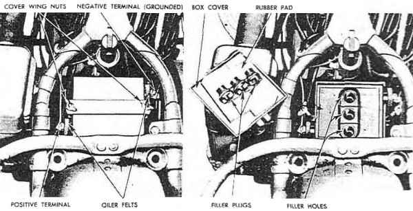
RA PD 310247 Figure 74—Battery Box Open and Filler Plugs Removed for Service
d. Install Battery. See that rubber mat is in place in bottom of battery box and install battery in box so that positive post is on left side of vehicle, and negative post is on right side of vehicle. Connect wires to battery positive and negative posts. Fit rubber mat on top of battery. Install cover and securely tighten thumb wing nuts. Lower saddle and bar assembly. Install swivel pin on right side of vehicle so that retaining spring fits in groove in end of swivel pin.
114. HEADLIGHTS.
a. Service Headlight.
(1) Remove nut which secures light body to bracket, observing that conical washer bears against cup of bracket for secure light mounting. Disconnect wires from light body terminals.
(2) Before installing service headlight, connect wires to light body terminals, noting that black wire with red tracer connects with the larger terminal screw. Mount light on bracket. Position conical‐shaped washer and lock washer and install mounting stud nut. Do not tighten mounting nut.
b. Adjust Service Headlight. Adjustment should be made in darkened area or at night, tactical situation permitting. Vehicle must be standing on a level surface about 25 feet away from and headed toward a wall or screen upon which a horizontal line has been drawn at exactly the same height as service headlight center. Set handle bar toggle switch in “BRIGHT” position and check light beam for height and direction. The top of main beam of light should register on wall or screen even with, but not higher than, the horizontal line mentioned. Tilt light body in bracket up or down to correctly aim it in relation to the horizontal line, making sure that light body is not turned either to right or left. Securely tighten mounting stud nut.
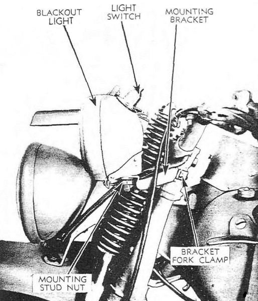
RA PD 310275 Figure 75—Blackout Headlight Installation
c. Blackout Headlight. Blackout headlight is mounted on bracket which attaches to left upper side of front fork. Blackout headlight operates when ignition and light switch is turned to the second right position. However, blackout headlight is fitted with an independent switch in light body to permit turning it off while other blackout lights are in use. Blackout headlight body is secured to mounting bracket by means of a conical washer, lock washer, and mounting nut, providing a swivel mounting to permit light adjustment.
d. Blackout Marker Light. The blackout marker light is secured to front mudguard by means of a hollow mounting stud, with plain washer, lock washer, and nut. Light wire passes through hollow stud and is protected by tubing on under side of mudguard. Blackout marker light wire connects with No. 1 post on ignition and light switch. Lamp is on with ignition and light switch in second right position.
115. TAILLIGHTS.
a. Blackout Stop and Taillight. Blackout stop and taillight is mounted on right side of taillight bracket. Light is provided with top unit to provide blackout stop light controlled by brake‐operated stop light switch. Bottom unit in the blackout stop and taillight is regularly used as service blackout taillight and is controlled by ignition and light switch.
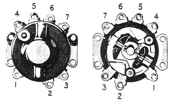
RA PD 310272 Figure 76—Ignition and Light Switch, Front and Back Positions
b. Service Stop and Taillight. Light is located on left side of light mounting bracket. Top unit is used for service stop and taillight (double filament lamp). Taillight filament is controlled by ignition and light switch; stop lamp filament is controlled by brake‐operated stop light switch. Stop light does not operate in daytime when ignition only is turned on. Bottom unit serves as a spare blackout taillight. In case the regularly used (right‐side) blackout taillamp fails, its socket plug can be transferred to this taillight socket.
c. Stop and Taillight Switch. This switch is operated by brake pedal and is located on end of rear support rod on right side of vehicle. Refer to wiring diagram (fig. 73) and paragraph 118 for wiring connections.
116. IGNITION AND LIGHT SWITCH.
a. Earlier models are provided with lock, later models are non‐locking.
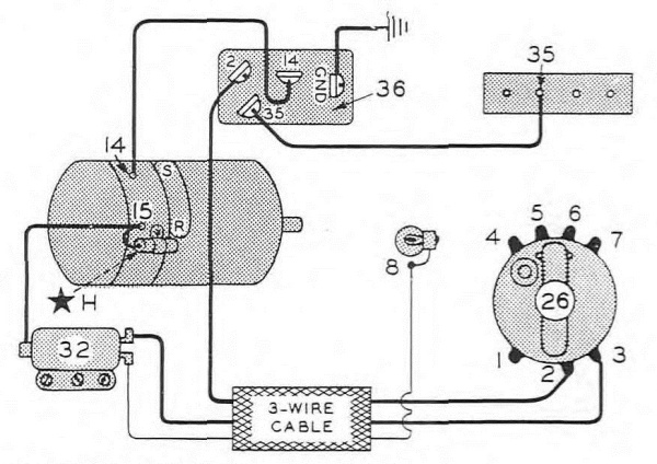
8—GENERATOR SIGNAL LIGHT.
14—GENERATOR TERMINAL TO SWITCH.
15—GENERATOR TERMINAL TO RELAY.
26—IGNITION‐LIGHT SWITCH.
32—RELAY.
35—TERMINAL STRIP BINDING POST.
36—MAGNETIC SWITCH FOR BLACKOUT LIGHT.
H—NOISE SUPPRESSION CONDENSER.
RA PD 310279 Figure 77—Blackout Headlight Magnetic Switch on Later Models
b. Remove. Disconnect battery ground wire. Remove instrument panel cover (par. 119). Disconnect all wires from switch. Remove the four switch mounting screws and spacers. Switch is now free for removal.
c. Install. Mount switch on instrument panel base. Install four screws and spacers. Connect wires (fig. 73). Connect battery negative ground wire to frame. Turn switch on. Check lights and horn, tactical situation permitting. Install instrument panel cover (par. 119).
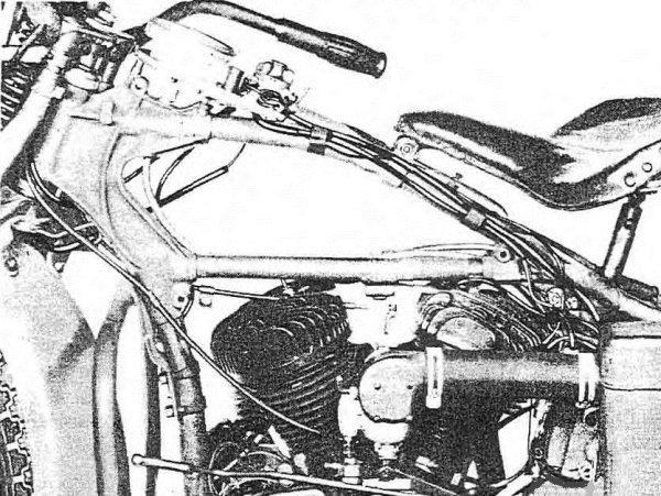
RA PD 310270 Figure 78—Wiring Cables, Left Side
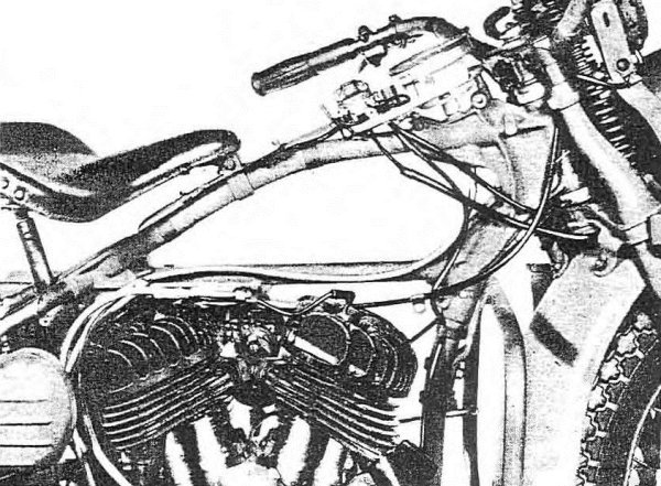
RA PD 310271 Figure 79—Wiring Cables, Right Side
117. HORN.
a. Description. Horn is mounted to headlight bracket by means of four bolts, lock washers, and nuts. One horn terminal is connected with operating button, and other terminal is connected to No. 4 ignition and light switch terminal (fig. 73).
b. Adjust. Tone adjusting screw is located in rear side of horn. If horn fails to operate and moving the adjusting screw does not remedy the trouble, horn must be replaced. NOTE: Do not change position of the adjusting screw located in center of diaphragm.
118. WIRING.
a. Cable System. Since ignition and lights are controlled by the ignition and light switch, all wires terminate at the ignition and light switch. Cables for wire protection are used, making it necessary to replace cables rather than individual wires. A study of figure 73 will be helpful when removing or installing any of the wiring cables. Also study figures 78 and 79 and note how cables are arranged on frame, and how they lead to the switch panel.
b. Remove and Install Cables. When it becomes necessary to replace wiring cables leading to the ignition and light switch, both fuel and oil tanks must be removed (par. 107) and instrument panel cover removed (par. 119) for accessibility.
Section XXIV INSTRUMENT PANEL
Paragraph
Panel cover119
Indicator lights120
Speedometer head121
119. PANEL COVER (fig. 80).
a. Remove. Remove speedometer light switch knob and remove screw. Remove hexagon‐head screw on front of cover. Remove two screws from side of cover. Remove two screws and washers which fasten plate to right side of cover. Lift cover off panel.
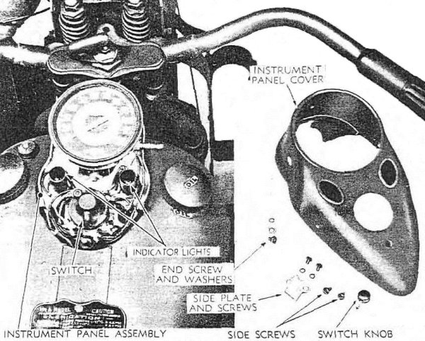
RA PD 315731 Figure 80—Panel Cover Removed
b. Install. Position cover on panel. Install two side mounting screws and washers and install hexagon‐head screw, plain washer, and lock washer in front end of cover. Attach cover side plate, installing two screws and washers. Install speedometer light switch knob and screw.
120. INDICATOR LIGHTS.
a. Three 2–c.p. single‐contact lamps are located on instrument panel. One for oil pressure (red) indicator light: one for generator‐charge (green) indicator light, and one for speedometer illumination.
b. Remove and/or Install. Remove and/or install panel cover (par. 119).
c. Test Generator‐Charge (Green) Indicator Lamp. Disconnect black wire from relay terminal (top terminal at front end of relay) and ground on relay base. Turn ignition and light switch on. Lamp should light. If it does not light, check wire for condition and/or replace lamp after removing panel cover (par. 119).
d. Test Oil Pressure (Red) Indicator Lamp. Disconnect wire from oil pressure switch. Ground the wire on engine. Turn ignition and light switch on. Lamp should light. If it does not light, check wire for condition and/or replace lamp after removing panel cover (par. 119). If lamp and wiring are satisfactory, replace oil pressure switch.
121. SPEEDOMETER HEAD.
a. Remove. Remove instrument panel cover (par. 119). Loosen the two tank front mounting bolts and remove rear mounting bolt to free speedometer cable clamp. Disconnect speedometer cable at drive unit. Free cable from clip located below tool box. Remove two screws which mount head to frame. Pull head upward, working cable forward under tank, until head and cable connection nut is clear of frame. Unscrew cable nut. NOTE: Cable may be secured to frame tube, between tanks, with friction tape. If so, cut tape.
b. Install. Attach speedometer head to cable end and tighten nut. Pass cable down into frame hole, pulling on rear of cable at same time. Mount speedometer head to frame with two screws and lock washers. Install panel cover (par. 119). Secure cable clamp under head of tank rear mounting bolt. Secure cable in clip, located under tool box. Attach end of cable to drive unit. Tighten the two tank front mounting bolts.
Section XXV TIRES, WHEELS, AND HUBS
Paragraph
Description122
Tires123
Rims and spokes124
Front wheel replacement125
Front wheel hub adjustment126
Rear wheel replacement127
122. DESCRIPTION.
a. Wheels have drop center rims to accommodate 4.00 x 18 tires. Front and rear wheels are not interchangeable. Front wheel hub is of ball‐bearing design, having cone adjustment similar to that of a bicycle hub. Rear wheel hub is of roller‐bearing design and must be taken apart for adjustment. Both wheels have “knock‐out” type axles.
123. TIRES.
a. Description. Wheel rims are of the drop‐center type, having a depression, or well, in center of rim. The rim well, being smaller in circumference than the rest of the rim, allows one casing bead to fit loosely in it while other bead is being worked over edge of rim. Bear in mind the importance of keeping one bead in rim well while other bead is being worked onto or off rim. NOTE: It is not always necessary to completely remove casing from rim. Removing one side only allows inner tube to be removed and reinstalled, and also allows inside of casing to be inspected.
b. Remove.
(1) Remove wheel from vehicle and lay wheel on its side. To remove front wheel, refer to paragraph 125. To remove rear wheel, refer to paragraph 127.
(2) Remove valve cap and valve core to free all air from tube.
(3) Press casing head into rim well to within a short distance of each side of valve.
(4) Using tire iron “B” in vehicle kit (fig. 11), start bead over edge of rim at valve. Do not use force when starting bead over edge of rim with tire iron, because bead wires may be broken or stretched, and tire ruined. With first bead in rim well, bead on other side can be started easily over edge of rim. After a portion of second bead is started over rim edge, casing can be further removed from wheel without aid of tire iron.
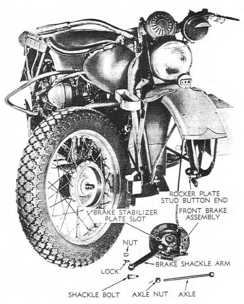
RA PD 310254 Figure 81—Disassembly for Front Wheel Removal
c. Install. Before applying casing to rim, see that rubber rim strip is in place in rim well and that rim strip valve hole alines with valve hole in rim.
(1) Start either bead of casing over rim edge. Work around wheel until entire bead is on rim.
(2) Place inner tube in casing. NOTE: Inner tube may be placed in casing before or after first bead of casing is on rim. Insert valve stem through hole in rim and start valve stem lock nut. While pressing first bead into rim well, work remaining bead over edge of rim, starting directly opposite valve stem. Work both ways around wheel toward valve.
(3) Inflate front tire to 18 pounds, and rear tire to 20 pounds.
(4) Reinstall front wheel (par. 125): reinstall wheel (par. 127). CAUTION: Tire casings are balanced and must be applied to rim with balance mark located at valve stem. On Firestone tires the balance mark is a red triangle, and on Goodyear tires a red dot.
124. RIMS AND SPOKES.
a. Wheels with broken and or missing spokes, with rims in badly kinked and or distorted condition, or having considerable run‐out, must be replaced.
b. Loose wheel spokes must be tightened evenly, being careful not to distort rim out‐of‐round or cause run‐out. Use spoke nipple wrench (41–W–3339) for front wheel spokes, and wrench (41–W–3340) for rear wheel spokes.
125. FRONT WHEEL REPLACEMENT (fig. 81).
a. Remove.
(1) Support vehicle on rear stand. Raise front end of vehicle by blocking up under frame loop on skid plate.
(2) Remove brake shackle bolt from rigid fork on left side of vehicle.
(3) Front axle is knock‐out type. Remove cotter pin and axle castle nut and pull out axle. Wheel is free for removal. CAUTION: Before removing axle note how slot in brake stabilizer plate is fitted over the extended (button) end of the left‐front rocker plate stud. It is necessary that this be correctly assembled when replacing front wheel.
(4) Roll wheel forward and remove brake assembly from brake drum, leaving the assembly attached to brake control wire and control wire housing.
b. Install (fig. 81). NOTE: At the time wheel and brake assembly is located in front fork, and before axle is installed, make sure that the curved slot in brake stabilizer plate engages with the button end of the left‐front rocker plate stud.
(1) Install brake assembly in brake drum.
(2) Roll wheel into position. Engage stabilizer plate notch and rocker plate stud button end, and at same time insert front axle.
(3) Install castle nut (no lock washer used) on axle and securely tighten.
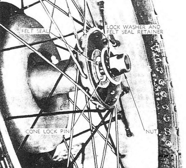
RA PD 310252 Figure 82—Front Hub Prepared for Cone Adjustment
(4) Use good cotter pin to secure nut.
(5) Install brake shackle bolt and special lock washer and nut. Tighten nut.
(6) Check front brake control wire and housing to make sure everything is in order and correctly adjusted (par. 97).
(7) Remove blocking from under vehicle.
126. FRONT WHEEL HUB ADJUSTMENT.
a. Front wheel, ball‐bearing hub, is similar to a bicycle front hub as far as adjustment is concerned. Do not completely disassemble hub for adjustment as balls are not in retainers, and will fall out when cone is removed. Hub is provided with grease deflector sleeve and felt retainer. NOTE: Earlier models are not equipped with grease deflector sleeve or felt retainer washer. Front wheel should have slight play or shake on bearings, and should turn freely.
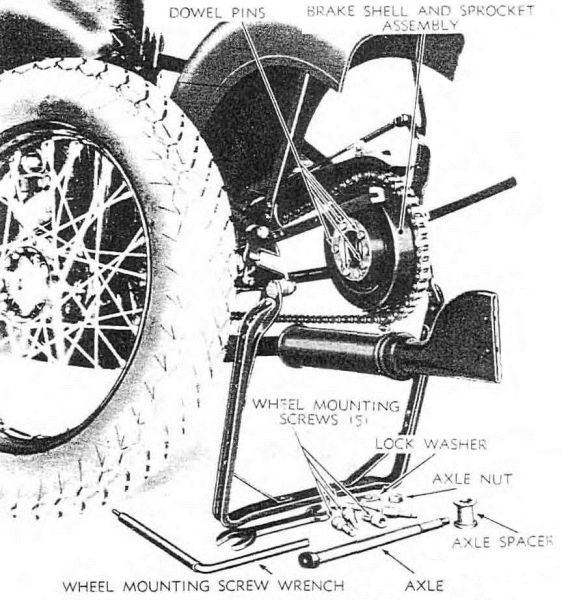
RA PD 315733 Figure 83—Disassembly for Rear Wheel Removal
(1) Remove front wheel (par. 125).
(2) Back off cone lock nut to end of axle sleeve. Do not remove nut.
(3) Turn cone on axle sleeve to the right (clockwise) to take up wheel play, and to the left (counterclockwise) to give more wheel play. Adjust so that wheel has slight play on bearing.
(4) Tighten cone lock nut. After tightening nut, again try for slight wheel play on bearing. Sometimes tightening lock nut takes up on bearing play. If necessary, readjust for desired results when cone lock nut is tight.
(5) Install front wheel and brake assembly (par. 125).
(6) Check adjustment of front brake.
127. REAR WHEEL REPLACEMENT (figs. 83 and 84).
a. Remove.
(1) Support vehicle on rear stand.
(2) Release mudguard rear stays. Loosen mounting nuts, and raise end of mudguard for wheel clearance.
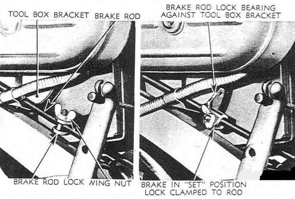
RA PD 310253 Figure 84—Brake Rod Lock
(3) Remove the five wheel mounting socket screws which secure wheel hub to brake shell and sprocket assembly. Use vehicle kit wrench “S” and sleeve (handle) “C” (fig. 11). NOTE: Wrench can be inserted from left side through holes in hub, and wheel must be turned to bring each mounting screw directly to the rear of axle for accessibility.
(4) Use brake rod lock to set and lock brake to prevent brake shell and sprocket from coming off brake assembly while wheel is being removed. Apply brake pedal and shift brake rod lock against tool box bracket, securing lock in this position with wing nut (fig. 84).
(5) Remove axle nut (right side of vehicle), using vehicle kit wrench “J” (fig. 11).
(6) Pull out axle from left side of vehicle.
(7) Remove spacer from between wheel hub end and left side of frame.
(8) Wheel is now free to come out by pulling and working it away from dowel pins located in brake shell assembly. A wheel being removed for the first time may offer some resistance. It will be observed that chain, sprocket, and brake assembly remain in the vehicle frame.
b. Install (figs. 83 and 84).
(1) Position wheel on brake shell dowel pins. Work hub onto dowels as far as it will go.
(2) Install axle spacer at left end of hub so that axle will pass through it and the hub.
(3) Install axle from left side of vehicle. Pass it through sleeve and hub, with end of axle engaging the frame left axle clip notch.
(4) See that lock washer is in place. Turn on and securely tighten axle nut, using vehicle kit wrench “J” (fig. 11).
(5) Loosen wing nut clamping brake rod lock. Move brake rod lock forward so that it will not strike any object when brake is operated; tighten wing nut to retain in position (fig. 84).
(6) Install and securely tighten the five wheel mounting socket screws.
(7) Lower mudguard into position and attach ends of rear stays. Securely tighten the clamping nuts.