PART TWO—VEHICLE MAINTENANCE INSTRUCTIONS (continued 2)
Reading edition
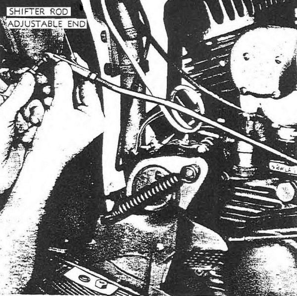
RA PD 310229 Figure 32—Adjusting Gear Shifter Rod
c. Adjusting Gear Shifter Control Linkage (fig. 32).
(1) Set hand lever in “N” (neutral) position in shifter guide.
(2) Remove nut and bolt to disconnect shifter rod from hand lever.
(3) With slight backward and forward movement of shifter rod, carefully “feel” transmission lever into exact position where shifter cam spring plunger (inside transmission) seats fully in cam‐locating notch.
(4) Next, see that hand lever is in exact “N” (neutral) position in tank shifter guide.
(5) Readjust length of shifter rod by loosening rod end lock nut, and turning rod end (onto or off rod as necessary) until its bolt hole lines up with bolt hole in hand lever.
(6) Replace bolt and tighten nut.
(7) Check Adjustment. It is advisable to shift hand lever into “L” (low) and “S” (second) gear positions and check shifter rod adjustment to be sure of having best all‐round adjustment.
(8) When shifter clutches become worn or damaged to the extent of jumping out of engagement under driving load, even though shifter control linkage is correctly adjusted, transmission must be removed and referred to higher authority for service.
55. REPLACEMENT OF FOOT STARTER CRANK.
a. Remove.
(1) Remove starter crank clamp bolt nut and remove bolt from crank.
(2) Pull starter crank off squared shaft.
b. Install. In installing foot starter crank, notch (for clamp‐bolt clearance) must be in upward position in squared shaft to put return spring tension on crank.
(1) Use a 5⁄8–inch, open‐end wrench and turn square shaft counterclockwise until bolt slot is upward. Hold shaft in this position and press starter crank onto shaft until clamping bolt can be inserted.
(2) Insert clamp bolt with bolt head toward rear wheel (crank in upward position) to provide clearance when starter crank is operated.
(3) Fit lock washer and nut and tighten nut securely.
56. REPLACEMENT OF STARTER CRANK SPRING (fig. 33).
a. Starter crank spring fits rather snugly behind rear edge of countershaft sprocket cover; however, it can be removed and installed without removing sprocket cover.
b. Remove.
(1) Remove foot starter crank (par. 55).
(2) With the blade of a screwdriver or with pliers, pry hooked end of spring off stud. NOTE: If spring is broken, this operation will not be necessary. Pull on spring end, at same time prying spring free of sprocket cover so as to pull spring off square shaft.
c. Install.
(1) Turn squared shaft so that clamp bolt notch is in bottom position. Engage square hole in spring on shaft with the hooked spring end to rear, in line with starter spring stud. Work spring onto shaft, prying it to rear to clear sprocket cover. Press all the way on squared shaft.
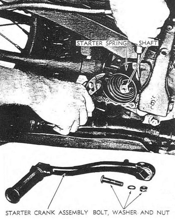
RA PD 315720 Figure 33—Removing Starter Crank Spring
(2) Hook end of spring in place on spring stud.
(3) Install foot starter crank (par. 55).
57. REMOVE TRANSMISSION (figs. 34 and 35).
a. Transmission and clutch are assembled in one unit and must be removed and installed together. To make sure trouble is in transmission, check clutch adjustment (par. 48) and transmission control linkage (par. 54) before replacing a faulty unit.
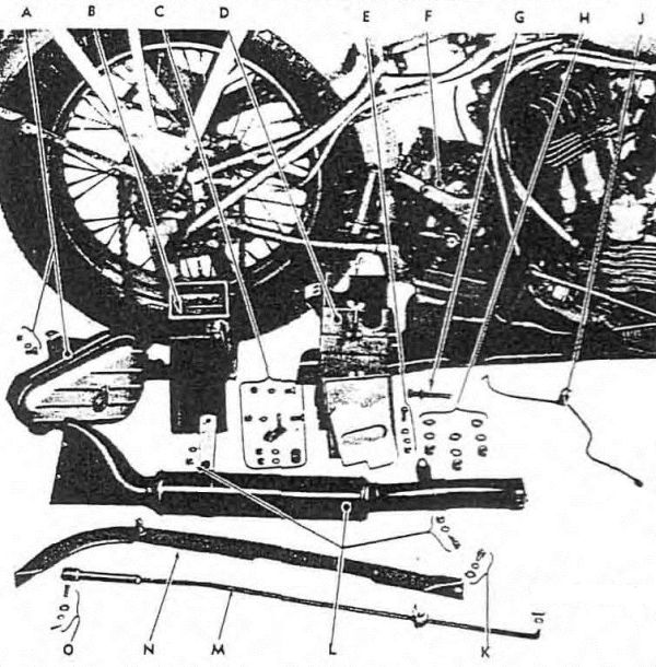
RA PD 315721
A—TOOL BOX AND BRACKET ASSEMBLY AND MOUNTING BOLT, WASHER AND NUT
B—BATTERY
C—BATTERY BOX REAR MOUNTING BOLTS, WASHERS, FITTINGS AND NUTS
D—BATTERY BOX ASSEMBLY AND COVER
E—BATTERY BOX FRONT MOUNTING BOLT, WASHERS AND NUT
F—TRANSMISSION AND CLUTCH ASSEMBLY
G—FRONT CHAIN ADJUSTING SCREW
H—TRANSMISSION MOUNTING STUD NUTS AND WASHERS
J—REAR CHAIN OILER PIPE
K—REAR CHAIN GUARD FRONT MOUNTING BOLT AND WASHERS
L—MUFFLER ASSEMBLY AND ATTACHING BOLT, WASHERS AND NUTS
M—REAR BRAKE ROD ASSEMBLY, WASHER AND COTTER PIN
N—REAR CHAIN GUARD
O—REAR BRAKE CLEVIS PIN, WASHERS AND COTTER PIN
RA PD 315721B Figure 34—Disassembly for Transmission Removal from Right Side
b. Remove.
(1) Drop rear end of skid plate (par. 111).
(2) Remove front chain guard (par. 102).
(3) Remove oil bath air cleaner and mounting bracket (par. 80). Lower bracket bolt also secures clutch cable tube to frame tube bracket on left side.
(4) Remove engine sprocket and front drive chain (par. 65).
(5) Remove the two mounting screws and locks in engine case to free inner front chain guard.
(6) Remove tool box from mounting bracket (par. 106). Remove bracket from frame.
(7) Remove rear brake rod (par. 96).
(8) Remove rear drive chain (par. 63).
(9) Remove rear drive chain guard (par. 102). Remove rear chain oiler pipe after disconnecting at oil pump.
(10) Remove battery box (par. 105).
(11) Remove nut, washer, and bolt securing clutch tube assembly bracket to frame bracket on right side of vehicle. Disengage clutch operating cable end from end of clutch release lever and remove cable and tube assembly.
(12) Remove gear shifter rod by disconnecting at hand shifter lever and at transmission gear shifter lever.
(13) Remove the three transmission mounting stud nuts, then remove lock washers and large plain washers (located under frame bracket), and lift transmission sufficiently to permit removal of front chain adjusting screw.
(14) Loosen upper U‐bolts on ignition coil mounting, then remove the lower U‐bolt nuts and shift coil on frame tube as far as possible toward the front.
(15) Remove transmission and clutch assembly from vehicle by lifting complete unit sufficiently to free mounting studs from frame bracket; then rotate top of transmission backward about ¼ turn (fig. 34) and remove unit from left side of frame (fig. 35).
58. INSTALL TRANSMISSION (figs. 34 and 35).
a. Install from Left Side. Working from left side of frame, tilt top of transmission backward, and as unit passes into position, rotate top forward, until unit is squarely in position and mounting studs pass through slots in frame mounting bracket.
(1) Shift ignition coil mounting back into correct position and tighten U‐bolt nuts.
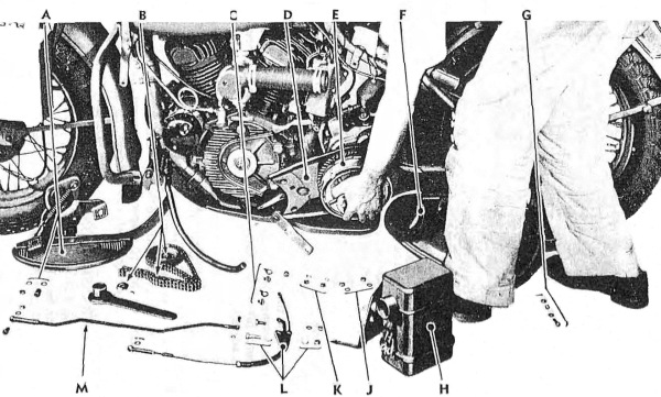
RA PD 315722 Figure 35—Disassembly for Transmission Removal from Left Side of Vehicle
A—LEFT FOOTBOARD, CLUTCH PEDAL AND SIDEBAR ASSEMBLY AND MOUNTING NUTS AND WASHERS
B—ENGINE SPROCKET, NUT, KEY AND FRONT CHAIN
C—INNER CHAIN GUARD MOUNTING SCREWS AND LOCKS
D—INNER CHAIN GUARD
E—TRANSMISSION AND CLUTCH ASSEMBLY
F—OUTER CHAIN GUARD
G—OUTER CHAIN GUARD REAR MOUNTING BOLT, WASHER, SPRING, NUT AND COTTER PIN
H—AIR CLEANER AND BRACKET ASSEMBLY
J—AIR CLEANER BRACKET UPPER MOUNTING BOLT NUTS AND WASHERS
K—SPARK COIL LOWER MOUNTING U‐BOLT NUTS AND WASHERS
L—CLUTCH CABLE AND HOUSING ASSEMBLY AND MOUNTING BOLTS, WASHERS AND NUTS
M—GEAR SHIFTER ROD ASSEMBLY WITH ATTACHING BOLT, WASHERS, PIN AND NUT
RA PD 315722B Legend for Figure 35—Disassembly for Transmission Removal from Left Side of Vehicle
(2) Install front chain adjusting screw. Lift transmission to engage screw in frame notch.
(3) Install large plain washers, lock washers, and nuts on the three transmission mounting studs. Do not tighten.
(4) Install gear shifter rod by connecting to hand shifter lever and transmission gear shifter lever.
(5) Install clutch operating cable and tube assembly. Connect cable end to clutch release lever. Position tube assembly bracket to frame bracket and install bolt, washer, and nut to hold in place.
(6) Install battery box (par. 105).
(7) Install rear drive chain guard (par. 102).
(8) Install rear drive chain (par. 63).
(9) Install rear brake rod (par. 96).
(10) Install tool box bracket and tool box (par. 106).
(11) Secure inner front chain guard to engine base by installing screw locks and screws. After screws are tightened, drift edge of each lock into screw slot for security.
(12) Install engine sprocket and front drive chain (par. 65).
(13) If necessary, adjust front drive chain (par. 59).
(14) Securely tighten transmission mounting stud nuts.
(15) Install outer front chain guard cover (par. 102). Connect rear chain oiler pipe to oil pump.
(16) Install air cleaner and mounting bracket, air hose, and connections (par. 79).
(17) Lift skid plate into position and install two mounting bolts, lock washers, and nuts.
(18) Check gear shifter control, and, if necessary, adjust linkage (par. 54).
(19) Check rear drive chain adjustment and adjust if necessary (par. 60).
(20) Check rear brake adjustment. If necessary, adjust rear brake linkage (par. 96).
(21) Check clutch controls and adjust if necessary (par. 48).
(22) Before operating vehicle, see that transmission oil level is up to filler opening (vehicle standing upright).
Section XV CHAINS AND SPROCKETS
Paragraph
Adjust front chain59
Adjust rear chain and aline rear wheel60
Chain oilers61
Replacement of front chain62
Replacement of rear chain63
Chain repair tool64
Replacement of engine sprocket65
Replacement of countershaft sprocket66
59. ADJUST FRONT CHAIN (figs. 36, 37, and 38).
a. At the time front chain adjustment is made, inspect chain for correct lubrication and, if necessary, adjust front chain oiler (par. 61).
b. Chains wear unevenly and some stretch may result, making tight and loose sections. For this reason, engine must be turned and chain rotated to position of least slack at the time adjustment is made.
c. A correctly adjusted front chain has ½–inch, or slightly more, free up‐and‐down movement midway between sprockets, at inspection hole. Chain must never be run taut (no slack at tightest point). Chain must never be allowed to run loose enough to cause jerky, noisy action and/or strike the chain guard.
d. Adjustment of front chain is made by shifting transmission on its mounting base. This will affect adjustment of gear shifter control linkage, clutch control linkage, and rear chain.
e. How to Adjust Front Chain.
(1) Remove inspection hole cover by removing screws and lifting cover from front outer chain guard, exposing chain (fig. 36).
(2) Obtain tightest chain position by rotating chain to position of least slack. Test amount of slack by lifting and depressing chain with finger. Use a free up‐and‐down motion of the finger to make this test.
(3) Loosen the three transmission mounting stud nuts underneath transmission mounting base. (It is not necessary to drop skid plate to reach stud nuts (fig. 37).) Transmission can now be shifted on its mounting base by means of adjusting screw, head of which protrudes through notch of frame fitting, located at rear of transmission (fig. 38).
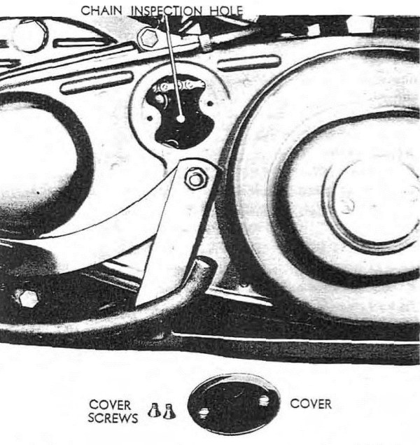
RA PD 310233 Figure 36—Front Chain Inspection Hole Cover Removed
(4) Turn adjusting screw clockwise (to the right) to move transmission backward and tighten front chain. Turn adjusting screw counterclockwise (to the left) to move transmission forward and loosen front chain.
(5) After moving transmission by means of adjusting screw, check front chain adjustment; then securely tighten the three transmission mounting stud nuts and again check chain adjustment, as tightening stud nuts sometimes changes chain adjustment.
(6) After front chain adjustment has been made, securely tighten the three transmission mounting stud nuts.
(7) Install front chain inspection hole cover and tighten screws.
(8) Check shifter lever control linkage adjustment (par. 54).
(9) Check clutch control linkage adjustment (par. 48).
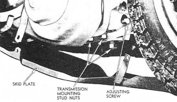
RA PD 310234 Figure 37—Skid Plate Dropped to Show Location of Transmission Mounting Nuts
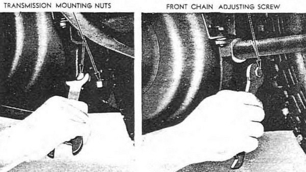
RA PD 310235 Figure 38—Transmission Mounting Nuts and Chain Adjusting Screw
60. ADJUST REAR CHAIN AND ALINE REAR WHEEL (fig. 39).
a. In moving transmission backward on its mounting to tighten front chain, the rear chain will be loosened. Rear chain must then be adjusted by moving rear wheel backward. When rear wheel is moved either forward or backward, adjustment of the rear wheel brake is affected.
b. When checking rear chain for slack midway between the sprockets, turn wheel and rotate chain to position of least slack. Use free up‐and‐down movement of finger to lift chain and depress it to determine tightest position.
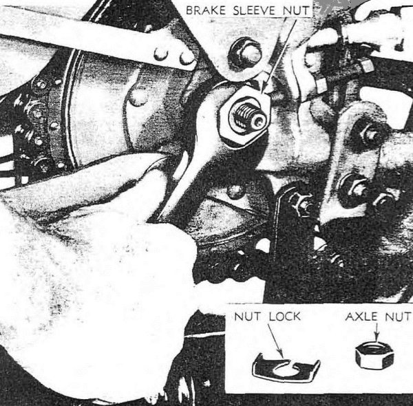
RA PD 310236 Figure 39—Brake Sleeve Nut
c. At position of least slack, a correctly adjusted rear chain has ½–inch, or slightly more, free up‐and‐down movement midway between sprockets. Chain must never be run taut (no slack at tightest point). Chain must never be allowed to run loose enough to cause jerky operation and/or strike the chain guard or other chassis parts.
d. At the time rear chain adjustment is made, inspect chain for correct lubrication and if necessary, adjust rear chain oiler (par. 61).
e. Rear chain adjustment and rear wheel alinement are both made by means of the rear wheel adjusting screws. Therefore, adjustment of either the chain or the wheel alinement can affect adjustment of the other, making it necessary to consider both adjustments at the same time.
(1) Remove rear axle nut and lock washer (right side of vehicle).
(2) Loosen brake sleeve nut enough to allow brake assembly to slide backward or forward in frame mounting (fig. 39).
(3) Loosen the two (right and left side) rear wheel adjusting screw lock nuts.
(4) Turn wheel adjusting screws clockwise (to right) to move wheel and sprocket backward. This tightens chain. NOTE: If chain is too tight, turn wheel adjusting screws counterclockwise (to left) so that wheel can be shifted forward. This will loosen chain. Always turn the two wheel adjusting screws an equal number of turns in order to keep wheel alined.
(5) Check correct alinement of wheel by noting that tire (not tire rim) runs approximately midway between lower rear frame tubes at the point where tubes join transmission mounting. It is desirable to have tire run slightly closer (not more than 1⁄16 in.) to right than to left side lower tube. A further check of alinement is observing that rear sprocket runs centrally in chain. CAUTION: If rear wheel is not correctly alined, vehicle steering will be affected, and sprockets will wear excessively on one side.
(6) With adjustment of chain and wheel alinement completed, securely tighten wheel adjusting screw lock nuts, and brake sleeve nut: replace axle lock washer and nut, tightening nut.
(7) Recheck adjustment of chain as tightening brake sleeve nut and axle nut sometimes changes the chain adjustment.
(8) After tightening rear chain, rear brake may be found too tight. Check and correct brake adjustment (par. 96).
61. CHAIN OILERS (fig. 40).
a. Both front and rear chains are automatically lubricated by engine oil pumps. Chain oilers are adjustable and may need occasional readjustment to meet lubrication requirements of varied operating conditions. Chains under most operating conditions require a very small amount of oil; therefore, chain oilers require very fine adjustment to supply just enough oil without waste.
b. When adjusting chain oilers, it is advisable to add or remove only one thin washer at a time and inspect chain again after vehicle has run approximately 100 miles, to determine whether or not further adjustment is necessary.
c. If inspection of front chain through inspection hole reveals that chain is not getting enough oil, adjust front chain oiler as follows:
(1) Add thin (0.002–inch thick) washer under head of front chain oiler adjusting screw (fig. 40). Do not remove any washers already under head of screw.
(2) To check results, refer to step b above.
d. Evidence of too much oil on front chain requires cutting down on chain oiler.
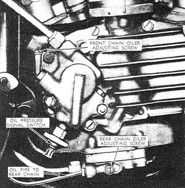
RA PD 310237 Figure 40—Chain Oilers
(1) To adjust oiler, remove thin (0.002–inch thick) washer from under head of front chain oiler adjusting screw (fig. 40).
(2) To check results, refer to step b above.
e. If inspection reveals that rear chain is not getting enough oil, and that oil pipe end is open, is not bent, and is directed on chain; then the rear chain oiler must be adjusted.
(1) Adjust oiler by adding thin (0.002–inch thick) washer under head of rear chain oiler adjusting screw (fig. 40). Do not remove any washers already under head of screw.
(2) To check results, refer to step b above.
f. Evidence of too much oil on rear chain (supplied by oiler) requires cutting down on chain oiler.
(1) To adjust oiler, remove thin (0.002–inch thick) washer from under head of rear chain oiler adjusting screw (fig. 40).
(2) To check results, refer to step b above.
g. At 1000–mile intervals, loosen both front and rear chain oiler adjusting screws (fig. 40) two turns each. Do not remove screws. Start and idle engine 1 minute, then tighten screws firmly, but do not force. This operation serves to flush oiler control valves and rear chain oiler pipe.
62. REPLACEMENT OF FRONT CHAIN.
a. A new or original duplex front chain is endless, not provided with connecting link, and engine sprocket must be removed in order to remove or replace chain.
b. Remove.
(1) Remove outer front chain guard (par. 102).
(2) Remove engine sprocket (par. 65). Chain can now be lifted off clutch sprocket.
c. Install. When installing a new front chain and/or sprocket, it may be necessary to shift transmission ahead in order to get chain on (par. 59 e).
(1) Clean engine shaft taper and sprocket hole.
(2) Place chain on clutch sprocket teeth and install sprocket (par. 65).
(3) Check chain adjustment (par. 59).
(4) Install outer front chain guard (par. 102).
63. REPLACEMENT OF REAR CHAIN (fig. 41).
a. Remove. Support vehicle on rear stand. With transmission in “N” (neutral) position, turn rear wheel until chain connecting link is located on rear sprocket teeth, about straight back from axle.
(1) Using pliers, lift split end of connecting link spring clip out of link pin notch, taking care not to damage spring clip. Remove spring clip from other link pin notch.
(2) Pull off link side plate and push link out of chain ends. Replace connecting link and spring clip in one end of chain to prevent its loss.
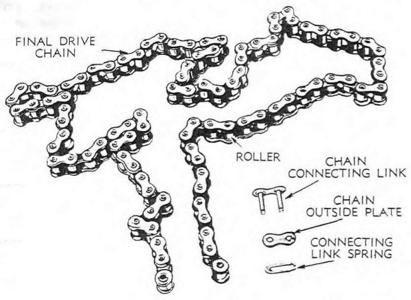
RA PD 310238 Figure 41—Rear Drive Chain and Connecting Link
(3) Pull on lower half of chain, guiding upper part while it rotates around countershaft sprocket, until removed. If a new rear chain is to be installed, one end can be linked to the upper half end of old chain and can be pulled onto countershaft sprocket as old chain is removed.
b. Install. When installing a new rear chain and/or countershaft sprocket, it may be necessary to set rear wheel ahead in order to get chain on (par. 60).
(1) Start end of chain over countershaft sprocket teeth, using starter crank to turn sprocket. After chain end has reached front half of sprocket, it will be necessary to guide end under sprocket and out of sprocket cover. Center chain so that ends engage rear sprocket teeth, back of the axle.
(2) Install connecting link, side plate and spring clip. See that open end of spring clip is to the rear with regard to chain travel (like the end of an arrow). If original spring clip is bent or damaged, use a new one.
(3) Adjust rear chain (par. 60).
(4) Check rear brake adjustment (par. 96).
64. CHAIN REPAIR TOOL (fig 42).
a. Damaged or broken chain links can be replaced with connecting (repair) links after bad links have been removed. To remove damaged or broken link, push out chain side plate pins with the chain repair tool (41–T–3320). Front chain is a double row of duplex chain; rear chain is a single row chain. The chain tool furnished in the tool kit is designed to accommodate both. To put a connecting link in the front chain, it will be necessary to remove front chain guard (par. 102).
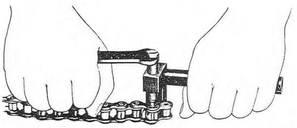
RA PD 310239 Figure 42—Chain Repair Tool in Use
b. When connecting (repair) links have been fitted to chain, make sure that spring clips are correctly and securely locked on link pin ends.
65. REPLACEMENT OF ENGINE SPROCKET.
a. Remove.
(1) Remove front outer chain guard (par. 102).
(2) Remove engine sprocket nut (right‐hand thread). It will be necessary to strike wrench with a hammer to loosen nut.
(3) Give flat surface of engine sprocket, near outer edge, a light but sharp rap with a hammer, being careful not to strike and damage sprocket teeth. Take care not to lose sprocket shaft key.
b. Install. If new sprocket is being installed, it may be necessary to shift transmission forward to get chain to fit on sprockets (par. 59).
(1) Thoroughly clean engine shaft taper and see that key is in place. Clean sprocket taper hole, fit front chain on sprocket teeth, and rotate chain until keyway in sprocket lines up with key in engine shaft. Slip sprocket onto engine shaft, install nut, and tighten securely. Strike wrench with a hammer to make sure sprocket nut is very tight.
(2) Install front outer chain guard (par. 102).
66. REPLACEMENT OF COUNTERSHAFT SPROCKET.
a. Remove.
(1) Remove foot starter crank (par. 55).
(2) Remove starter crank spring (par. 56).
(3) Remove countershaft sprocket cover (par. 52).
(4) Bend back extension of sprocket nut lock.
(5) Remove sprocket retaining nut. It will be necessary to strike wrench with a hammer to loosen nut.
(6) Give sprocket a light but sharp rap with a hammer near outer edge, being careful not to strike the sprocket teeth, and remove sprocket from shaft taper. Do not lose the two sprocket shaft keys.
b. Install.
(1) Clean shaft taper and taper hole in countershaft sprocket. Install the two keys.
(2) Install sprocket on shaft. Place rear chain on sprocket before installing sprocket cover.
(3) Examine nut lock and, if badly damaged, use a new one.
(4) Install sprocket retaining nut. Tighten by striking wrench with a hammer. NOTE: This nut must be tight. Bend up extension of nut lock against side of nut.
(5) It will be easier to install starter crank spring at this step to avoid interference with sprocket cover.
(6) Install sprocket cover.
(7) Install starter crank.
Section XVI FUEL SYSTEM
Paragraph
General67
Carburetor adjustment68
Throttle control wire adjustment69
Carburetor removal70
Carburetor installation71
Fuel strainer72
Carburetor bowl cleaning73
Fuel pipe74
67. GENERAL.
a. Carburetor is of the side‐outlet, plain‐tube type with a fixed venturi. Fuel feed is by gravity from tank above. Carburetor has two manual controls: the throttle, which is operated by the right handle bar grip, and the choke, which is operated by a lever on the carburetor itself. The high speed fuel supply is governed by a fixed (non‐adjustable) jet. The idling to medium speed (30 mph) fuel supply is governed by an adjustable (low speed) needle valve located on rear side of carburetor body.
68. CARBURETOR ADJUSTMENT (fig. 43).
a. Before attempting to adjust carburetor to correct faulty engine performance, attention should be given other items which have a direct bearing on and can affect carburetor adjustment as well as engine performance.
(1) Inspect fuel tank cap and make sure air vent is not plugged.
(2) See that throttle control adjustment is correct (par. 69).
(3) See that spark control adjustment is correct (par. 88).
(4) Drain and flush carburetor bowl (par. 73).
(5) Drain and flush fuel strainer (par. 72).
(6) Inspect air cleaner to see that passage of air through cleaner is not restricted by oil level being too high in oil cup, or by an excessive accumulation of dirt in filter elements (par. 76).
(7) Check manifold packing nuts and carburetor mounting screws for tightness.
(8) See that spark plugs are clean and that gaps are adjusted between 0.025 inch to 0.030 inch. If condition of spark plugs is questionable, install new ones.
(9) Check adjustment of valve tappets (par. 43).
(10) Check compression of both cylinders (par. 29 b.) (1)
(11) Check condition and adjustment of circuit breaker points (par. 84).
(12) Check ignition to battery wiring connections (diagram fig. 48).
(13) See that battery is not entirely discharged by turning on lights (tactical situation permitting) and observing brilliancy.
b. A carburetor, once correctly adjusted, should require little, if any, readjusting. At most, it should not be necessary to adjust the low speed needle more than one or two notches either way to correct mixture to meet changes in weather conditions.
c. Low Speed Adjusting Needle (figs. 43 and 44). Adjustment of this needle valve controls only idling and low speed (up to approximately 30 mph) fuel mixture. Turn needle valve down (to right) to make mixture leaner. Back out (to left) needle valve to make mixture richer. Needle valve is held in any desired position by a spring‐and‐ball plunger which engages notches in the needle adjusting screw.
d. Complete Readjustment of Carburetor. A carburetor that is badly out of adjustment, and/or a new carburetor just installed, must be adjusted as follows:
(1) Turn the low speed needle valve all the way down (to right).
(2) Back needle valve out (to left) about three full turns. With needle valve in this position, engine will start, but mixture will probably be too rich.
(3) Start engine as follows: After choke lever has been moved to normal open running position and engine is normally hot, correct adjustment of needle valve by turning needle valve down (to right) one notch at a time until mixture becomes so lean that engine misses, and is inclined to stop: then back out (to left) needle valve 5 to 10 notches, or until engine fires regularly with spark advanced and throttle closed (or as nearly closed as it can be set and still have engine running at idling speed).
(4) Adjust throttle lever stop screw (fig. 43) as necessary to make engine idle at proper speed with throttle in fully closed position. Turning stop screw to the right makes engine idle faster. Turning stop screw to the left makes engine idle slower. Do not idle engine at the slowest possible speed, because an extremely slow idling adjustment causes hard engine starting. Changing idling speed with throttle stop screw is likely to change the low speed fuel mixture to some extent: therefore, it will be necessary to again check and correct the low speed needle valve adjustment (step (3) above).
(5) Engine starting and all‐round carburetion will be improved with low speed fuel adjustment slightly rich, rather than extremely lean.
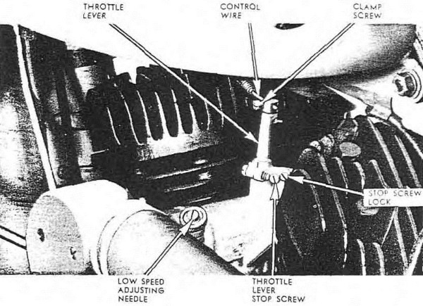
RA PD 310240 Figure 43—Throttle in Fully Closed Position
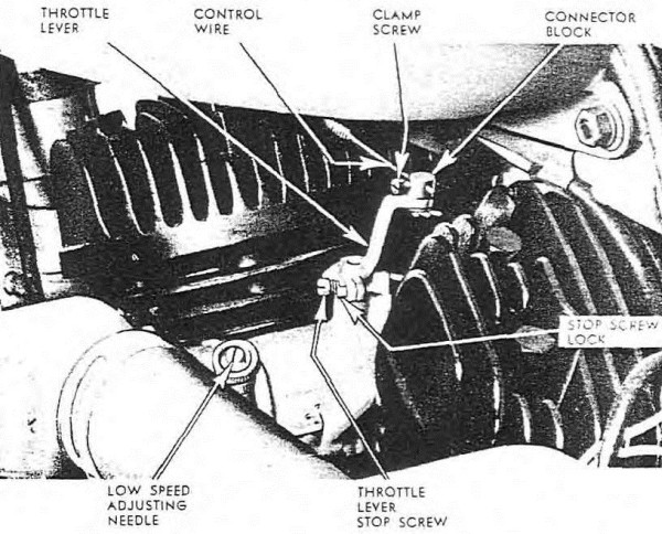
RA PD 310241 Figure 44—Throttle in Fully Open Position
69. THROTTLE CONTROL WIRE ADJUSTMENT (figs. 43 and 44).
a. Carburetor throttle is opened and closed by means of the right handle bar grip, operating a control wire (within a housing) which connects to the throttle lever. Adjustment for full opening and closing of the throttle to correspond with full inward and outward motion of the handle bar grip is made at the junction of the control wire end and the throttle lever connection.
b. Adjust Fully Closed Throttle (fig. 43). See that there is about 1 inch distance between end of control wire housing and throttle lever when in fully closed position, so that housing end does not interfere with forward movement of throttle lever. If adjustment of control wire housing is necessary, refer to paragraph 101. Proceed with closed throttle adjustment.
(1) Loosen control wire clamp screw in connector block.
(2) Turn right handle bar grip outward as far as it will go: then turn it inward slightly. Holding throttle grip in this position, move throttle lever forward against its stop (closed position) and secure control wire in connector block with clamp screw. Check closing of throttle after tightening control wire set screw. If necessary, reset the control wire in the connector block until throttle is closed with full outward grip movement.
c. Adjust Fully Open Throttle (fig. 44). Follow instructions under step b above, then:
(1) Turn right handle bar grip inward as far as it will go and see that throttle lever is against its stop in fully open position. If throttle does not open fully when grip is turned inward, reset the control wire in the connector block to correct the adjustment.
70. CARBURETOR REMOVAL.
a. Remove Carburetor for Replacement Only.
(1) Shut off fuel supply valve.
(2) Loosen connector block clamp screw and disconnect throttle control wire at throttle lever.
(3) Disconnect fuel feed pipe at strainer nipple.
(4) Loosen air cleaner hose clamp at carburetor air intake fitting, and remove four screws and air intake fitting from carburetor.
(5) Remove the three mounting bolts (from right side of vehicle) which secure carburetor to manifold flange. CAUTION: Take care not to damage or lose gaskets found between carburetor flange and manifold flange, and/or ½–inch thick steel spacer fitted between carburetor and manifold on some models.
(6) Remove carburetor.
(7) Remove fuel strainer assembly from carburetor bowl nipple.
71. CARBURETOR INSTALLATION.
a. When installing carburetor be sure to fit the ½–inch thick steel spacer (if one was originally fitted) between carburetor and manifold flanges, with two gaskets on one side and one gasket on the other side. Later models have a longer manifold neck, extending carburetor farther to the left, away from cylinders, and do not need the spacer.
(1) Install fuel strainer assembly on bowl nipple. Leave coupling nut loose until after fuel pipe is connected.
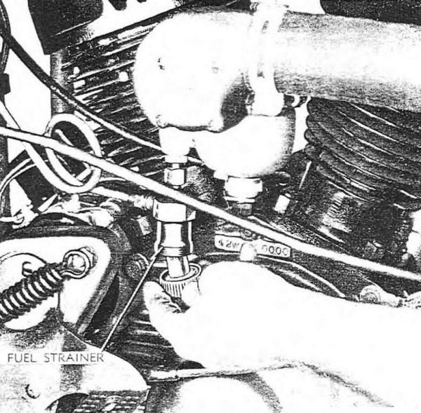
RA PD 310242 Figure 45—Removing Fuel Strainer
(2) To install carburetor on manifold, locate carburetor flange and two gaskets (½–inch steel spacer and gaskets if originally fitted) to aline with holes in manifold flange, and insert and securely tighten the three carburetor mounting screws. Use a 7⁄16–inch socket wrench, or a large screwdriver, to securely tighten these screws. NOTE: If carburetor manifold is loose in manifold packing nuts (carburetor can be lifted and manifold turns in packing nuts), tighten manifold nuts securely, using manifold wrench (41–W–1570–10).
(3) Insert carburetor air intake fitting into end of air hose and mount fitting on carburetor with the four screws. Tighten air hose clamp.
(4) Connect fuel pipe to fuel strainer nipple by tightening the union nut and also the strainer union nut on bowl nipple.
(5) Attach throttle control wire to throttle lever connector block and adjust (par. 69).
(6) Open fuel supply valve and observe for leaks.
(7) Adjust carburetor (par. 68).
72. FUEL STRAINER (fig. 45).
a. Cleaning.
(1) Shut off fuel supply valve.
(2) Unscrew cap from bottom of strainer body.
(3) Lift strainer screen element with cork washer out of cap and clean thoroughly. Remove any dirt or sediment collected in cap. NOTE: If compressed air is not available for cleaning, gasoline from the fuel pipe can be used for cleaning screen and cap.
(4) Install one cork washer in bottom of cap, set strainer screen element in place, and locate the other cork washer over screen element. Turn cap with screen element and washers onto bottom of strainer body, handtight.
b. Remove Strainer Assembly.
(1) Shut off fuel supply valve.
(2) Disconnect fuel feed pipe at strainer body nipple.
(3) Remove filter assembly from carburetor bowl nipple. It will be noted that coupling nut is an integral part of the filter body assembly.
c. Install Strainer Assembly.
(1) Install fuel strainer assembly on carburetor bowl nipple. Leave coupling nut loose until after fuel pipe is connected.
(2) Connect fuel pipe to strainer body nipple and tighten union nut. Strainer coupling nut can now be tightened on bowl nipple.
(3) Open fuel supply valve. Inspect fuel pipe and coupling nuts for leaks.
73. CARBURETOR BOWL CLEANING.
a. Water from fuel, water moisture, and dirt entering air cleaner will settle in bottom of carburetor bowl and will interfere with engine starting and carburetion. At periodic intervals bowl must be drained. NOTE: Before draining and flushing bowl, clean fuel strainer (par. 72).
(1) Support vehicle on jiffy (side) stand.
(2) Shut off fuel supply valve.
(3) Remove bowl drain screw. Let fuel, water, and dirt run out of bowl. With drain screw still removed, open fuel supply valve (turn to left) and leave open only a few seconds, to allow fresh gasoline to flush out bowl.
(4) Replace bowl drain screw, taking care to avoid thread crossing. Set screw snug, but not tight enough to strip the threads.
74. FUEL PIPE.
a. Remove.
(1) Shut off fuel supply valve.
(2) Remove pipe union nut from tank nipple. Remove pipe after disconnecting union nut from fuel strainer body nipple.
b. Install. Fuel pipe must be installed without putting undue twist or strain on pipe or end fittings. Therefore, bend and/or shape pipe to “fit” between nipple connections before replacing and drawing up on union nuts.
(1) Connect lower end of pipe to fuel filter body nipple. Do not tighten nut.
(2) Connect upper end of pipe to tank nipple. Securely tighten this nut. Next, tighten union nut on strainer body nipple.
Section XVII INTAKE AND EXHAUST SYSTEM
Paragraph
Description75
Air cleaner76
Hose and carburetor fitting77
Remove air cleaner78
Install air cleaner79
Replacement of air cleaner mounting bracket80
Exhaust system81
75. DESCRIPTION.
a. Intake System. The air intake system consists of oil bath air cleaner, connecting air hose, and carburetor intake hose fitting. This system is located on left side of vehicle.
b. Exhaust System. The exhaust system consists of muffler and tailpiece assembly, front exhaust pipe assembly, and rear exhaust pipe. Exhaust pipe ends are a slip fit in cylinder exhaust ports.
76. AIR CLEANER (figs. 46 and 47).
a. General. Air cleaner should not be submerged in water, nor should high‐pressure stream be directed into cleaner louvers (where air enters on rear of body) when cleaning vehicle. Either water or dirt entering air cleaner in excessive quantities will raise the oil level in oil cup and choke off proper air supply to carburetor.
b. Service. With vehicle in normal use on hard‐surfaced roads, clean and refill air cleaner oil cup with engine oil (seasonal grade) at least each time engine oil tank is drained and refilled. CAUTION: Service more frequently under dusty conditions; daily under extremely dusty conditions. Check oil supply daily.
(1) Hold oil cup with one hand and release (unlatch) oil cup retaining spring clips to remove oil cup.
(2) If oil in cup is clean, with no signs of dirt and grit in oil or cup, but the oil level is below the indicated level mark, add engine oil (seasonal grade) to bring level up to mark. NOTE: If oil and cup are dirty, empty out oil and wash out cup with dry‐cleaning solvent. Refill with clean engine oil (seasonal grade) to indicated level mark.
(3) Before installing oil cup make sure that the oil cup gasket is in place and in good condition.
(4) Check baffle plate thumb screw for tightness.
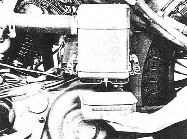
RA PD 310243 Figure 46—Air Cleaner Oil Cup Removed
(5) Install oil cup, making sure that retaining spring clips are fully engaged in lip of oil cup and hold oil cup securely to cleaner body.
(6) Oil bath air cleaners on earlier models are of “round” type, oil cup being secured to body with a metal clamp band and thumb screw. When oil cup is removed on this type of cleaner, the baffle plate will come out with the cup. Make sure that baffle plate is correctly installed and that gasket is in place when installing cup.
c. Maintenance (fig. 47). The rectangular‐type oil bath air cleaner is provided with two filter elements, retained in filter body by means of the baffle plate. If daily check reveals excessive accumulation of dirt and grit in oil and cup, filter elements must be removed and cleaned. NOTE: Check several times daily under extremely dusty or sandy conditions.
(1) Hold oil cup with one hand and release (unlatch) oil cup retaining spring clips; remove cup.
(2) Unscrew baffle plate thumb screw and remove baffle plate.
(3) Filter elements may “bind” in cleaner body. If so, rap side of body with hand to loosen them; or, if necessary, withdraw elements from body with pliers or a hooked wire.
(4) Check for presence and condition of gasket above the two filter elements (in filter body); also for oil cup gasket.
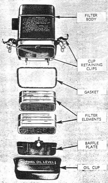
RA PD 310244 Figure 47—Air Cleaner, Disassembled
(5) Clean both filter elements thoroughly in dry‐cleaning solvent. Allow elements to dry out (use air hose if available).
(6) Clean oil cup and refill to indicated level mark. Use clean engine oil (seasonal grade).
(7) Dip one screen surface of each filter element about ½ inch into oil in the oil cup (to “oil wet” filter pack). Install the two filter elements, baffle plate, and oil cup immediately after “oil wetting” the filter elements. Make sure gaskets are in place. NOTE: Do not add more oil to oil cup after elements have been dipped into it, because excess oil absorbed by elements will drip back into oil cup, bringing level back to normal.
(8) Round‐type oil bath air cleaner used on earlier models does not have removable filter element. Complete cleaner body must be removed from vehicle, immersed and agitated in cleaning solvent to wash out dirt. After cleaning, allow filter element to dry (use air hose if available), then apply a few squirts of engine oil to inside of cleaner element, using oilcan. Refill cup, replace baffle plate and cup, securely tightening clamp band thumb screw.
77. HOSE AND CARBURETOR FITTING.
a. Remove. Carburetor intake and hose connection must be removed from carburetor to remove and/or install air hose.
(1) Loosen screws in the two hose clamps.
(2) Remove four screws retaining carburetor air intake fitting. Remove carburetor fitting from end of hose, and pull hose off air cleaner body connection.
b. Install. Before installing air hose, inspect for breaks or faulty condition that might prevent airtight seal between air cleaner and carburetor fitting.
(1) Install one end of hose on carburetor fitting. Do not tighten clamp screw.
(2) Install other end of hose on air cleaner connection. Do not tighten clamp screw.
(3) Install carburetor fitting. Securely tighten the four screws. Next, center air hose between carburetor fitting and air cleaner connection and securely tighten hose clamp screws.
78. REMOVE AIR CLEANER.
a. Loosen hose clamp screw at air cleaner body connection and remove two nuts and gear‐toothed washers from bolts securing air cleaner assembly to frame bracket. NOTE: Gear‐toothed lock washers are also used under heads of the two mounting bolts. Withdraw cleaner from end of air hose.
b. The same procedure applies to round‐type air cleaners used on earlier models.
79. INSTALL AIR CLEANER.
a. Engage air cleaner hose connection in end of hose and mount cleaner assembly on frame bracket with two bolts, gear‐toothed lock washers, and nuts. Securely tighten mounting nuts. NOTE: The plated (whitened) mounting bolts, four gear‐toothed lock washers, and bolt nuts must effect a ground connection between bracket and filter mounting to insure adequate radio bonding. Tighten air hose clamp screw at cleaner body connection.
b. The same procedure applies to round‐type air cleaners used on earlier models.
80. REPLACEMENT OF AIR CLEANER MOUNTING BRACKET.
a. Air cleaner mounting bracket and air cleaner can be removed or installed as an assembly.
b. Remove.
(1) Loosen hose clamp connection at air cleaner body.
(2) Disconnect battery ground wire. This prevents shorting battery when removing cleaner bracket clamp bolt.
(3) Remove the two upper cleaner bracket frame clamp bolts.
(4) Remove lower mounting bolt. Cleaner lower bracket mounting and clutch cable tube mounting are secured to frame bracket by the same whitened radio bonding bolt, gear‐toothed lock washers, and nut. Remove nut and drop bolt to free cleaner bracket.
c. Install.
(1) Engage air hose and cleaner body connection.
(2) Attach lower bracket first. Locate cleaner bracket so that hole lines up with bolt holes in frame bracket and clutch cable tube mounting. Pass whitened radio bonding bolt upward through bracket hole, install shakeproof lock washer, and securely tighten nut.
(3) Attach bracket to the two upper frame clips. Tighten the clamp bolt nuts.
(4) Connect battery ground wire.
(5) Tighten air hose clamp screw at cleaner connection.
81. EXHAUST SYSTEM.
a. Remove Muffler Assembly.
(1) Support vehicle on rear stand.
(2) Remove bolt from end of hanger bracket on left side of vehicle, and remove bolt from muffler clamp and skid plate bracket on right side of vehicle. Drop skid plate.
(3) Loosen nut and bolt on clamp which secures front end of muffler at exhaust pipe connection (clamp is attached to muffler).
(4) Remove muffler rear hanger bracket bolt nut. Pull muffler assembly free from exhaust pipe connection.
b. Install Muffler Assembly.
(1) Engage muffler pipe and exhaust pipe at muffler pipe clamp connection. Do not tighten clamp bolt nut as yet.
(2) Attach muffler rear hanger bracket to frame bracket bolt, installing lock washer, and tightening nut. NOTE: It may be advisable to loosen hanger bracket on muffler so that muffler can be lined up for front end connection.
(3) Tighten muffler and exhaust pipe clamp bolt nut and rear hanger nut.
(4) Raise skid plate into position and install right side mounting bolt which secures muffler front bracket and skid plate bracket to frame clip. Tighten all mounting nuts.
c. Remove Exhaust Pipes.
(1) Refer to step a (1), (2), (3) above.
(2) Remove right side footboard and brake pedal assembly as follows: Loosen footboard rear support stud nut, remove front support stud nut, and pull footboard outward to free end of safety guard. Remove bolt which secures front exhaust pipe clamp, and remove nut from rear support rod, freeing stop light switch and rear end of footboard sidebar. Remove nut from front support rod, and drop footboard and brake foot pedal assembly to provide clearance for exhaust pipe removal. Disengage rear exhaust pipe at cylinder port, at same time prying and pulling front exhaust pipe forward and downward to free from cylinder port. Both exhaust pipes can now be worked downward and removed from vehicle as an assembly.
d. Install Exhaust Pipes.
(1) Position exhaust pipe (front and rear) assembly, working it into position so that front pipe end slips into cylinder port; then, pry and force rear pipe end into rear cylinder port.
(2) Mount footboard, brake foot pedal, and sidebar assembly on support rods, installing washer and nut on front support rod.
(3) Position and mount stop light switch on rear support rod. See that spring and operating control wire exert a straight pull on switch plunger when foot pedal is operated.
(4) Install bolt, washer, and nut which secure front exhaust pipe clamp to footboard sidebar.
(5) To attach safety guard to sidebar, pull front end of footboard away from sidebar, line up holes in sidebar and safety guard end, then pass footboard support stud through both pieces, and secure with washer and nut.
(6) Tighten footboard rear support stud nut.
(7) To complete installation, follow procedure outlined in step b (1) through (4) above.
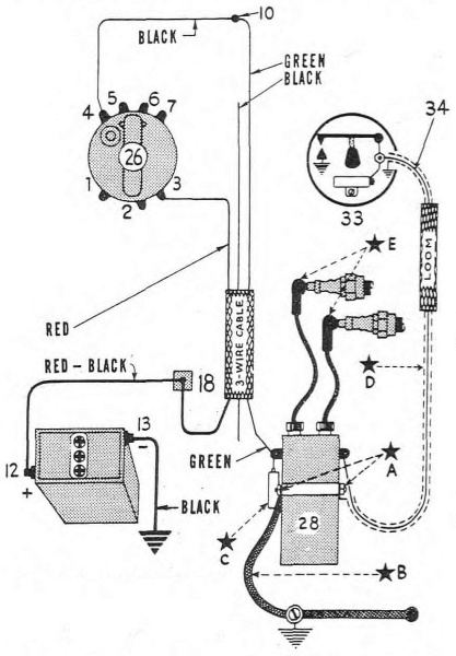
10—INSTRUMENT PANEL TERMINAL.
12—BATTERY POSITIVE.
13—BATTERY NEGATIVE (GROUND).
18—TERMINAL JUNCTION ON FRAME.
26—IGNITION—LIGHT SWITCH.
28—SPARK COIL.
33—CIRCUIT BREAKER.
34—COIL TO TIMER WIRE.
*A—RADIO BOND, COIL TO TIMER WIRE.
*B—RADIO BOND, COIL TO ENGINE.
*C—NOISE SUPPRESSION CONDENSER.
*D—SHIELDED COIL TO TIMER WIRE.
*E—SPARK PLUG SUPPRESSORS.
RA PD 315723 Figure 48—Ignition to Battery Wiring Diagram
Section XVIII IGNITION SYSTEM
Paragraph
Description82
Spark plugs83
Circuit breaker points84
Condenser85
Circuit breaker and timer assembly86
Coil to timer wire87
Adjust spark control88
Spark coil89
82. DESCRIPTION.
a. The ignition system differs from that of the conventional automotive types in that it has no distributor. A circuit breaker alone is used. Both coil high‐tension winding ends lead directly to both spark plugs. Thus both plugs spark at the same time, one cylinder being on compression stroke while the other cylinder is on exhaust stroke.
83. SPARK PLUGS.
a. Defective spark plugs are indicated by engine missing, overheating, knocking excessively, and lacking normal power.
b. Type. Spark plugs are medium heat range, manufacturer’s (H–D) No. 3.
c. Cleaning. Do not take plugs apart for cleaning. Use the sandblast cleaner method.
d. Point Adjustment. Bend electrode located in plug base to adjust point gap 0.025 inch to 0.030 inch.
e. Replacement. Use spark plug wrench (41–W–3334) to install plugs, using new gaskets. Never draw a cool plug up tight in a hot cylinder head, rather turn down snug and wait l/2 minute until plug base is warm: then tighten securely. CAUTION: Take care not to cross‐thread when installing spark plug.
84. CIRCUIT BREAKER POINTS (fig. 49).
a. Circuit breaker lever is insulated from ground and connects to primary wire binding post by means of a “pig‐tail” wire. Stationary point is grounded to timer base and is movable in order to adjust circuit breaker points. Circuit breaker points that are burned or pitted should be renewed or dressed with a clean fine‐cut, contact point file. The file should not be used on other metals and should not be allowed to become greasy or dirty. CAUTION: Never use emery cloth to clean points. Contact surfaces, after considerable use, may not appear bright and smooth, but this is not necessarily an indication that they are not functioning satisfactorily.
b. Remove Breaker Lever.
(1) To disconnect condenser terminal, remove nut from end of condenser and remove gear‐toothed washer, plain washer, and the brass terminal strip. Do not remove fiber washer and plain washer located back of brass terminal strip on condenser terminal post.
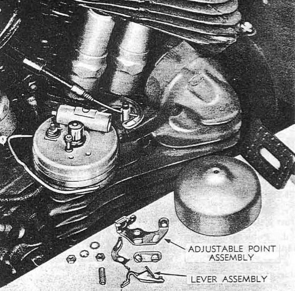
RA PD 310248 Figure 49—Circuit Breaker Points Removed
(2) Bend brass terminal strip down and remove binding nut which secures brass terminal strip and breaker lever “pig‐tail” to primary wire binding post.
(3) Compress breaker lever spring at end of lever, disengaging spring. CAUTION: Do not lose spring. Release and remove lever from insulated pivot post.
c. Remove Adjustable Contact Point.
(1) Remove the two lock screws and washer plate, securing adjustable contact point assembly to timer base. Point assembly is free to be lifted off lever pivot stud.
d. Install Adjustable Contact Point.
(1) Install contact point assembly, replacing washer plate and the two lock screws. Do not tighten lock screws until circuit breaker points are adjusted (step f below).
e. Install Breaker Lever.
(1) Install brass terminal strip on primary wire binding post.
(2) Connect end of brass terminal strip to condenser terminal post. Install flat washer, gear‐toothed washer, and nut.
(3) Install breaker lever on pivot post insulated bearing.
(4) Install breaker lever spring. Make sure that ends of spring are retained correctly.
(5) NOTE: Keep breaker lever cam very lightly greased.
f. Adjusting Circuit Breaker Points (fig. 51).
(1) Correct point gap is 0.022 inch. Circuit breaker point faces must seat squarely against each other. If bent, square up and aline by bending contact plate. Turn timer breaker cam until breaker lever fiber is located on highest point of cam.
(2) With the adjustable point lock screws loose, shift the adjustable point plate to obtain a 0.022–inch gap between the circuit breaker points. Measure gap with an accurate thickness gage before retightening lock screws, and again recheck point gap after tightening the lock screws. NOTE: Wrong circuit breaker point gap affects ignition timing.
85. CONDENSER.
a. The condenser is connected in parallel with the circuit breaker points, one of its terminals being grounded (for the adjustable point) to the timer base by means of the mounting screw, the other terminal making connection with the circuit breaker lever (for the lever point) by means of the lever “pig‐tail.”
b. Remove.
(1) Unlatch circuit breaker cover retainer and remove cover.
(2) Remove nut from end of condenser and remove gear‐toothed washer, plain washer, and the brass terminal strip. NOTE: A small plain washer and a large fiber washer are located behind brass terminal strip.
(3) Remove screw which secures condenser to timer base. Remove condenser.
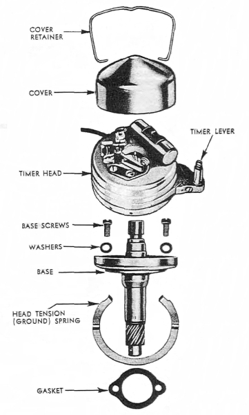
RA PD 310249 Figure 50—Circuit Breaker (Timer), Disassembled
c. Install.
(1) Mount condenser on timer housing. Install lock washer and screw. Make sure small plain washer and large fiber washer are in place on condenser end terminal screw before connecting the brass terminal strip.
(2) Connect brass terminal strip to condenser. Replace plain washer, gear‐toothed washer and terminal nut.
(3) Install circuit breaker cover.
86. CIRCUIT BREAKER AND TIMER ASSEMBLY (figs. 50 and 51).
a. When the circuit breaker timer shaft and base assembly must be replaced due to excessive wear in timer shaft bearing, sheared worm gear pin, and/or worn or damaged worm gear, engine ignition must be retimed. Ignition timing for the V‐type twin engine is difficult and should be attempted only by experienced personnel.
b. Remove (fig. 50). Before the timer shaft and base assembly can be removed, the circuit breaker timer head assembly must be removed. NOTE: If the timer head only, or timer wire, is to be replaced, it is not necessary to remove timer shaft and base assembly, and thus throw engine ignition out of time.
(1) Remove timer head cover.
(2) Unlatch cover retainer ends from holes in the timer head and remove.
(3) Disconnect spark control wire at timer lever.
(4) Lift the timer head assembly off base. The head seating tension (ground) spring (underneath shaft base) is also free, and can now be removed. NOTE: It is not necessary to disconnect timer to coil wire from timer head terminal post, unless head or wire is being replaced.
(5) Remove the two timer base mounting screws and lock washers. It will be noted that one screw grounds the timer to coil wire shielding.
(6) Timer shaft and base assembly can now be lifted out of engine gear case cover. Take care not to damage or misplace base gasket.
c. Install Timer Shaft and Base Assembly and Timing Ignition (fig. 51). This calls for retiming engine ignition as follows: (NOTE: Circuit breaker cam turns in clockwise direction):
(1) Unscrew and raise front cylinder inlet valve spring cover, using tappet wrench (41–W–3617).
(2) Turn engine in direction in which it runs until valve tappet indicates front cylinder is on compression stroke (directly after front cylinder intake valve closes).
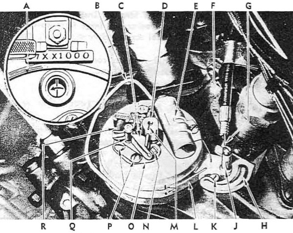
A—FLYWHEEL TIMING MARK IN CRANKCASE INSPECTION HOLE.
B—COVER RETAINER.
C—CIRCUIT BREAKER LEVER.
D—CIRCUIT BREAKER CAM.
E—CONDENSER.
F—SPARK CONTROL WIRE HOUSING.
G—SPARK CONTROL WIRE.
H—SPARK LEVER QUADRANT.
J—SPARK LEVER.
K—TIMER HEAD ADJUSTING BAND SCREW.
L—TIMER HEAD ADJUSTING BAND.
M—MARK ON BREAKER CAM AND MARKS ON TIMER HEAD AND HAND INDICATING ORIGINAL FACTORY TIMING.
N—CIRCUIT BREAKER POINTS.
O—ADJUSTABLE CONTACT POINT PLATE.
P—ADJUSTABLE CONTACT POINT LOCK SCREWS.
Q—CIRCUIT BREAKER LEVER PIVOT (INSULATED).
R—BREAKER LEVER SPRING.
RA PD 310281 Figure 51—Circuit Breaker Marks and Flywheel Mark Correctly Alined
(3) Remove plug from timing inspection hole in left‐side crankcase.
(4) Continue turning engine slowly until flywheel timing mark is in center of inspection hole (fig. 51). Do not turn engine further.
(5) Install paper gasket and timer head tension (ground) spring on timer shaft base assembly. Make sure bent ends of tension spring are facing downward (away from timer base).
(6) Insert timer shaft and base assembly all the way down into place in timing gear case cover, trying to locate mark on small end of breaker cam in position shown in figure 51. Do not install base mounting screws as yet.
(7) Install timer head assembly so that spark control lever is within the advance and retard quadrant (fig. 51). NOTE: Do not install cover retainer until later.
(8) Fully advance spark lever (push inward toward engine) and observe how closely mark on breaker cam lines up with breaker lever fiber. If mark does not line up, lift timer base and turn shaft gear so its engagement with its driving gear is changed one tooth. Check again according to breaker cam mark and breaker lever fiber. Repeat this procedure until gear engagement is obtained which closely alines cam mark and breaker lever fiber.
(9) See that timer base is turned so that timer to coil wire is toward rear of engine.
(10) Install timer base screws and lock washers. Make sure that timer to coil wire shielding is grounded under head of screw farthest away from engine (fig. 52). Securely tighten screws.
(11) Install timer head on base and secure with ground spring and cover retainer. Be sure ground spring is in its proper place so that when cover retainer ends are fitted through holes in the timer head, they will also fit into spring locating notches. It will be necessary to press ground spring upward under timer base to engage retainer ends in the spring notches. NOTE: If cover retainer ends do not engage ground spring notches, spring will have no tension and timer head will be loose on its base. Circuit breaker points and condenser are electrically grounded through timer base, and ground spring holds the head and base in close contact, thus assuring a good ground.
(12) Connect spark control wire and timer lever and adjust (par. 88).
(13) Engine is now timed according to original factory setting, providing mark on side of timer head and hole in head adjusting band are still in alinement, and circuit breaker point gap is 0.022 inch. Even though all ignition timing marks are in perfect alinement, as outlined in the foregoing instructions, it is advisable to accurately check ignition timing (step d following).
d. Recommended Recheck of Ignition Timing (fig. 51). Even though all ignition timing marks are in perfect alinement, as when engine was originally timed, ignition timing may change somewhat after engine has been in service for a while, due to normal wear and seating of the various moving parts that can affect ignition timing. Since accurate ignition timing is the first essential to good engine performance, it is advisable to check ignition timing on new vehicle after first 1,500 miles of service, and at each 2,000 miles thereafter.
(1) See that circuit breaker points are adjusted for correct gap of 0.022 inch (par. 84 f).
(2) Advance timer lever fully (toward engine).
(3) Turn engine in direction in which it runs until front cylinder is on compression stroke, and continue to turn it ahead slowly until narrow timer cam (the end with the timing mark), just starts to open the circuit breaker points.
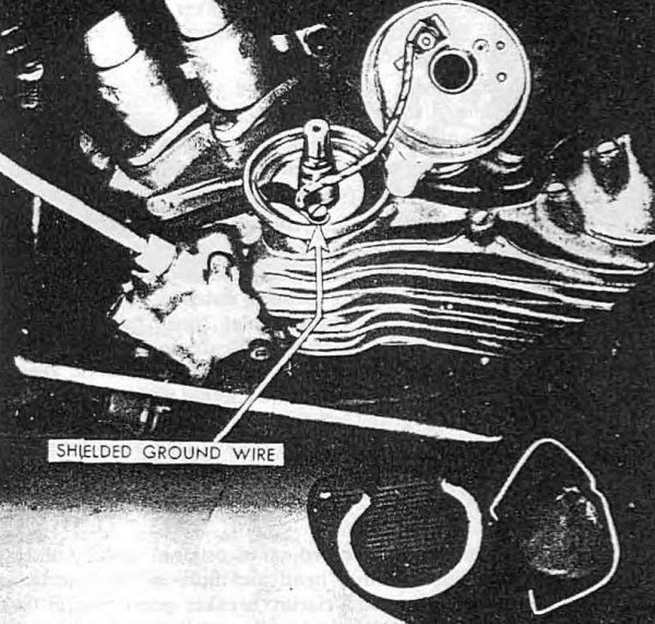
RA PD 318205 Figure 52—Shielding of Coil to Timer Wire Grounded on Base
(4) An accurate test light check as to when points just start to break can be made, using the instrument panel red light for the purpose. Disconnect panel light wire from the oil pressure switch, attaching this wire to the insulated terminal post on timer head. Turn ignition and light switch on. As long as circuit breaker points are closed, lamp will remain lit; as points start to open, lamp will go out. NOTE: After making use of instrument panel red light for above purpose, reconnect wire to oil pressure switch.
(5) When exact position is found, where points just start to open, flywheel mark should be in the center of the inspection hole.
(6) If flywheel mark is not in center of hole when points open, readjust ignition timing as necessary (slower or faster) by means of the timer head and band adjustment.
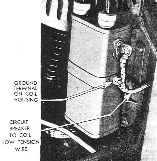
RA PD 318203 Figure 53—Shielded Coil to Timer Wire Correctly Connected at Coil
(7) To readjust timer head, loosen adjusting band screw and shift timer head in band. If flywheel timing mark shows forward of center in inspection hole, the timing is slow. To correct, shift timer head counterclockwise against rotation of breaker cam. If flywheel mark is to rear of center of inspection hole, timing is fast and timer head must be shifted with rotation (clockwise) of breaker cam, to correct timing.
(8) With ignition timing correct, front cylinder piston is 9/32 inch before top dead center, on compression stroke, when circuit breaker points just start to open. At this point spark occurs, igniting front cylinder fuel charge.
(9) Install flywheel inspection hole plug in left crankcase.
87. COIL TO TIMER WIRE (figs. 52 and 53).
a. Models provided with radio shielding are identified by “S” on either side of instrument panel. The coil to timer wire (low‐tension wire) on these models is shielded for radio noise suppression.
b. Remove.
(1) Disconnect battery negative ground wire at frame connection.
(2) Remove the two bolts which secure upper end of air cleaner bracket to frame tube. Swing air cleaner and bracket outward and forward to gain access to spark coil rear terminal.
(3) Disconnect coil to timer wire terminal from coil rear connection. Disconnect wire shielding from coil rear ground connection.
(4) Refer to paragraph 86 b (1) to (4) for timer head removal.
(5) Remove timer base mounting screw which secures wire shielding (fig. 52).
(6) Note position of coil to timer wire inside of timer head; then remove nut washer connecting wire to insulated contact stud.
(7) Work old wire and loom out of timer head hole and free from vehicle.
(8) On earlier models, the coil to timer wire was soldered to end of insulated stud. Removal of stud is necessary to remove this wire, or replace it with a shielded wire. Note location of stud insulations on inside and outside of timer head, for correct installation when reassembling.
c. Install.
(1) Pass end of wire, shield terminal, and loom up through hole in timer base.
(2) Ground the wire shield terminal under head of timer base mounting screw (fig. 52).
(3) Connect wire end terminal to insulated stud so that wire leads away from stud in direction shown (fig. 52).
(4) Pass coil to timer wire up alongside and to rear of frame saddle post tube to reach rear of spark coil.
(5) Ground the wire shield terminal to coil rear ground connection (fig. 53).
(6) Connect wire terminal to coil rear primary connection (fig. 53).
(7) Install timer head on base (par. 86 c (11)).
(8) Connect spark control wire to timer lever and adjust (par. 88).
(9) Connect battery negative post wire to frame ground terminal.
(10) Swing air cleaner bracket back into place and install two bolts, washers, and nuts securing bracket to frame clips.
(11) Replace timer cover and check engine for starting.
88. ADJUST SPARK CONTROL.
a. Spark advance and retard is controlled by left handle bar grip. Spark lever operates within a quadrant mounted on engine. Spark must be fully advanced (lever inward toward engine) when handle bar grip is turned inward to full extent of its travel. When handle bar grip is turned outward, spark lever retards (lever outward away from engine).
(1) With control wire in lever stud and clamp screw loose, turn left grip fully inward; then back it out just a little.
(2) Shift spark lever inward toward engine as far as it will go; then tighten control wire clamp screw. Test by turning left grip fully inward and noting position of spark lever. It should be against inner side of quadrant (fig. 51). Retard spark and check position of lever within quadrant; it should be against outer side of quadrant.
(3) Check final adjustment. Readjust full advance and retard timer lever positions as necessary when left grip is turned inward, and outward, respectively.
89. SPARK COIL (fig. 54).
a. Spark coil high‐tension cables go directly to the spark plugs, no distributor being used. When the coil is faulty, it must be replaced, since internal repairs are not possible. The high‐tension cables can be replaced, however. Coil is provided with a condenser for radio noise suppression, and metal coil case is grounded to engine by bonding.
b. Remove.
(1) Disconnect battery negative ground wire from frame connection.
(2) Free high‐tension cable ends (with radio noise suppressors) from spark plugs. Free front cylinder high‐tension cable from clip at upper engine frame mounting.
(3) Loosen air intake hose connection at carburetor fitting.
(4) Remove two nuts, washers, and bolts securing upper end of air cleaner mounting bracket to frame clamps.
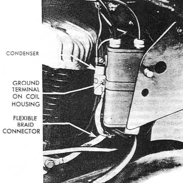
RA PD 318204 Figure 54—Coil Front Connections Showing Radio Bonding and Noise Suppression Condenser
(5) Swing air cleaner and bracket assembly outward to gain access to coil rear terminals.
(6) Disconnect coil to timer wire from coil rear terminal screw. Disconnect wire shielding from coil rear ground terminal (fig. 53).
(7) Swing cleaner back and remove wire connections from coil front terminal screw (fig. 54).
(8) Disconnect radio bonding at coil front ground terminal (fig. 54).
(9) Remove nuts and bolts which mount coil to bracket. Coil is now free for removal.
c. Install.
(1) Mount coil on frame bracket with high‐tension cables upward, and reinstall mounting bolts, lock washers, and nuts. Tighten nuts.
(2) Connect terminals of the two green wires to coil front terminal screw. Refer to wiring diagram, figure 48.
(3) Connect radio bonding to coil front ground terminal. Tighten nut securely.
(4) Connect coil to timer wire terminal to coil rear terminal screw. Connect wire shielding to coil rear ground terminal. Tighten nut securely.
(5) Swing air cleaner and bracket assembly back in place and install two bolts, lock washers, and nuts securing bracket to frame clamps. Tighten nuts securely.
(6) Connect battery negative ground wire to frame connection.
(7) Pass front cylinder high‐tension wire under tank, secure in cable clip at upper engine frame mounting, and attach cable end (radio noise suppressor) to front spark plug. Attach rear high‐tension cable end (radio noise suppressor) to rear spark plug.
(8) Check wiring connections (fig. 48) and test coil by engine starting.
Section XIX GENERATING SYSTEM
Paragraph
Description90
Clean commutator91
Armature bearing special lubrication92
Remove generator93
Install generator94
Cut‐out relay95
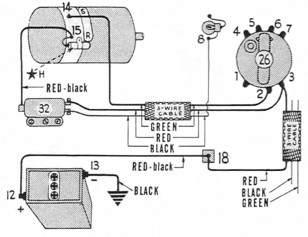
8—GENERATOR SIGNAL LIGHT
12—BATTERY POSITIVE TERMINAL
13—BATTERY NEGATIVE TERMINAL (GROUND)
14—“SWITCH” TERMINAL OF GENERATOR
15—“RELAY” TERMINAL OF GENERATOR
18—FRONT JUNCTION TERMINAL
26—IGNITION AND LIGHT SWITCH
32—CUT‐OUT RELAY
*H—NOISE SUPPRESSION CONDENSER
RA PD 317200 Figure 55—Generator to Battery Wiring Diagram
90. DESCRIPTION (fig. 55).
a. The generator is shunt connected. The two field coils, regulating coil, and shunt coil are not connected in series in the conventional manner. The regulating field coil provides adequate current output (approx. 4 amperes) for daytime operation. The shunt field coil is controlled through the ignition and light switch to increase current output (approx. 8 amperes) when vehicle lights are in use. Generator uses the third (regulating) brush system of current regulation. A cut‐out relay serves as a magnetic switch in the generator‐battery circuit, also operating the instrument panel green signal light to indicate generator charge.
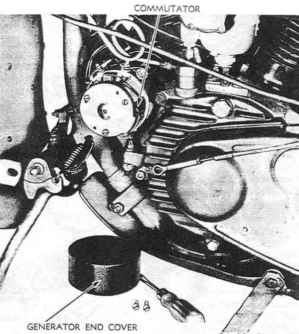
RA PD 310259 Figure 56—Generator Cover Removed for Commutator Cleaning
91. CLEAN COMMUTATOR (fig. 56).
a. If battery is in good condition, cut‐out relay is functioning, and wiring connections are made according to diagram (fig. 55), yet generator does not charge or charge rate is low, proceed to clean the commutator.
(1) Remove left footboard, sidebar, and clutch foot pedal assembly, following procedure outlined under paragraph 102 a (1) to (6), to permit generator cover removal.
(2) Remove the two end cover screws and pull end cover off generator.
(3) Clean armature commutator with No. 00 sandpaper until bright and clean. Blow out with air. CAUTION: Do not remove or disturb brushes in their holders. Never use emery cloth to clean the commutator.
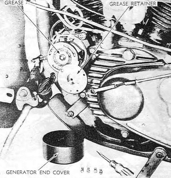
RA PD 310260 Figure 57—Generator End Cover and Grease Retainer Removed
(4) Temporarily install footboard assembly and operate engine, to observe whether or not generator is charging (green signal light goes off at above 20 mph). If cleaning commutator does not remedy generator charge, and/or commutator is badly worn, then generator must be replaced (par. 93). If cleaning of commutator remedied generator charge, reinstall generator end cover, and the footboard and clutch pedal assembly (par. 102 b).
92. ARMATURE BEARING SPECIAL LUBRICATION (fig. 57).
a. At the 6,000–mile second echelon preventive maintenance service period, the commutator end bearing must be hand‐packed. In performing this operation, care must be taken not to shift or move the generator third (regulating) brush, thus disturbing generator current regulation. Generator drive end bearing is adequately lubricated by oil circulating through engine.
b. To Lubricate Commutator End Bearing.
(1) Remove left footboard, sidebar, and clutch pedal assembly, following procedure outlined in paragraph 102 a (1) to (6).
(2) Remove the two end cover screws and pull end cover off generator.
(3) Remove two of the three screws which secure the outer grease retainer plate to end of generator (fig. 57).
(4) Loosen the other grease retainer plate screw slightly to permit shifting plate to one side.
(5) Pack ball bearing with general purpose grease No. 2, pressing lubricant into bearing with finger.
(6) Shift the outer grease retainer plate back into position. Install the two screws removed, and securely tighten all three screws.
(7) Install generator end cover and the two retaining screws.
(8) Install left footboard, sidebar, and clutch foot pedal assembly, following procedure outlined in paragraph b.
93. REMOVE GENERATOR (figs. 58 and 59).
a. Generator is gear driven through engine timing gear train. Generator can be removed and installed without removing timing gear case cover, or affecting alinement of timing gears.
b. Before replacing generator because of failure of instrument panel green signal light to indicate charge, check panel light wiring and bulb for good condition (par. 120).
c. When it has been determined that generator must be removed for replacement, proceed as follows:
(1) Disconnect wires from the two generator terminals marked SWITCH and RELAY.
(2) Remove the two long screws, through timing gear case cover, that secure end of generator against gear case (fig. 58).
(3) Remove strap nut, lock washer, and curved washer from end of strap that clamps generator in its cradle on engine crankcase (fig. 59).
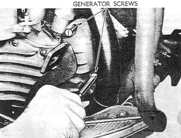
RA PD 310261 Figure 58—Removing Generator End Mounting Screws
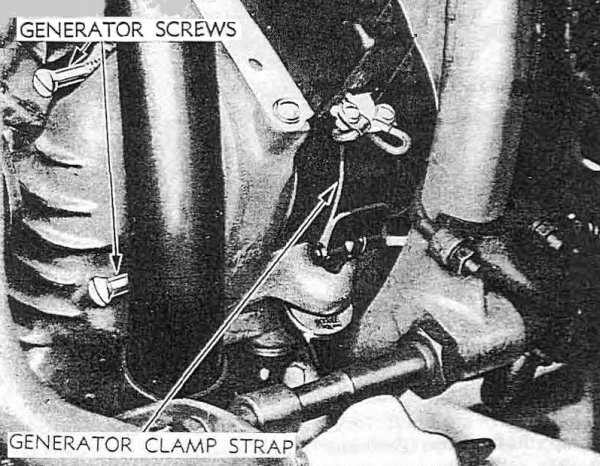
RA PD 310262 Figure 59—Removing Generator Strap Nut
(4) Lift strap high enough to permit raising generator so that oil slinger (on end of generator gear) will clear adjacent gear, and allow generator to be removed from engine. Be sure to observe and count number of paper shims between generator and cradle. Lay these shims aside to be used again when generator is reinstalled. Also, note location of hole in shims for oil drain. These shims were required in original assembly to adjust driving gears for proper mesh and, if left out, gears may mesh too deeply and “howl,” even though considerably worn. Unless a new generator gasket is available, to be used when generator is reinstalled, be careful not to damage the old one.
94. INSTALL GENERATOR.
a. When installing generator, the important point to consider is correct shimming of generator in its cradle to provide correct mesh of driving gear with intermediate timing gear. Make sure same number of paper shims are used in reassembling as were found underneath generator when it was removed. After an engine has been run a considerable length of time and gears have worn to some extent, they have possibly developed sufficient lash or play to safely remove one or more of the original shims, and thus affect closer meshing and quieter operation. However, this should not be done unless timing gear case cover is removed so that gear mesh and lash can be carefully checked.
(1) Pass generator drive gear end through gear case hole, lifting generator so that oil slinger clears intermediate timing gear. Turn generator in its cradle so that end holes line up with long mounting screws which pass through gear case cover. Tighten mounting screws securely.
(2) Install curved washer, lock washer, and nut on end of clamp strap; tighten nut securely.
(3) Connect red‐black wire to generator terminal marked RELAY, and green wire to generator terminal marked SWITCH. Refer to wiring diagram (fig. 55).
(4) Operate engine and check generator for current output, as well as check for gear noise. If shimming under generator is proper, generator and timing gears will run quietly. If necessary, readjust shimming until gears operate quietly.
95. CUT‐OUT RELAY.
a. Operation of the instrument panel green signal light, indicating generator charge, is controlled by the cut‐out relay. Therefore, if relay is faulty the signal light will not operate properly, falsely indicating generator trouble. Rust around the contact points, burned points, and loss of armature spring tension are sources of most relay trouble. NOTE: Before condemning a relay because of failure of green signal light, make light test (par. 120).
b. Correct adjustment of relay point gaps and tensioning of armature springs require use of precision electric meters and expert knowledge on the subject. A faulty relay, other than removing cover and cleaning with air, should be replaced. No adjustment of points should be attempted.
c. Remove.
(1) Disconnect the three wires from relay terminal screws.
(2) Remove the two mounting screws and lock washers. Remove relay from engine base.
d. Install.
(1) Mount relay on engine base with two screws and lock washers. Make sure that mounting is clean to make good electrical ground contact between relay and engine.
(2) Reconnect the three wire terminals to relay terminal screws. Follow wiring diagram, figure 55.
(3) Operate engine and observe action of relay, also action of instrument panel green signal light to indicate generator charge.
Section XX BRAKE SYSTEM
Paragraph
Rear wheel brake96
Front wheel brake97
96. REAR WHEEL BRAKE (figs. 60, 61, and 62).
a. Linkage. Brake foot pedal on right side of vehicle is connected to bell crank (located on rear footboard support rod) by means of the front brake rod (nonadjustable). The bell crank is connected to rear brake operating lever by means of the rear brake rod with adjustable clevis end.
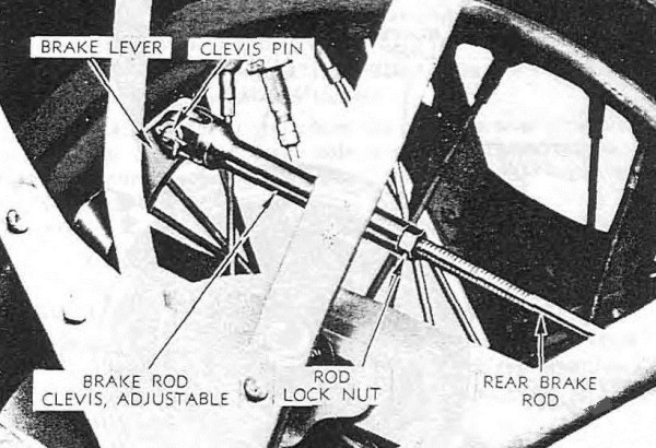
RA PD 310277 Figure 60—Rear Brake Adjustment
b. Adjusting Rear Wheel Brake (fig. 60). If brake operating lever stands ahead of vertical position, excessive lining wear is indicated. Brake shoes must be replaced (steps c and d below). Normal free play of brake foot pedal before brake operation is 1 inch. After brake takes effect in vehicle operation, brake foot pedal should have 1–inch reserve travel before bottoming on footboard. If brake foot pedal operation does not come within these limits, adjust rear brake rod as follows:
(1) Remove cotter pin, plain washer, and clevis pin from end of rear brake rod clevis.
(2) Loosen clevis lock nut on brake rod.
(3) Turn clevis onto (clockwise) brake rod to shorten rod and take up foot pedal free play.
(4) Turn clevis off (counterclockwise) brake rod to lengthen rod and increase foot pedal free play.
(5) After making brake adjustment, spin rear wheel and make sure brake is not dragging. When correct brake adjustment is attained, install clevis pin in clevis and brake operating lever with plain washer, and retain with cotter pin. NOTE: Cotter pin must be in good condition.
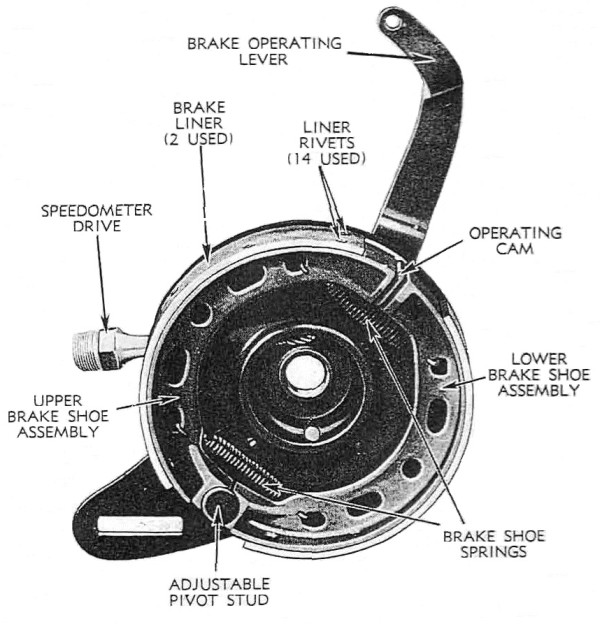
RA PD 310273 Figure 61—Rear Brake Assembly
c. Remove Brake Shoes (fig. 61).
(1) Remove rear wheel (par. 127).
(2) Remove brake drum and sprocket assembly. Brake shoes are now accessible. Do not remove side cover assembly from frame.
(3) Disconnect brake rod clevis at brake operating lever.
(4) Place end of large screwdriver blade between ends of brake shoes at pivot stud. Move brake‐operating lever forward to hold brake shoes in fully expanded position, and pry ends of shoes off pivot stud without removing brake shoe springs.
d. Install Brake Shoes. Observe that brake shoes are made for upper and lower positions and are not interchangeable. Recess in end of shoe for pivot stud head determines position of shoe in assembly.
(1) Engage ends of springs in shoe assembly holes from the inside before installing shoes on side cover (fig. 61).
(2) With brake shoes and springs assembled, install so that ends of shoes will slip over pivot stud and shaft‐operating cam.
(3) Connect brake rod clevis to brake operating lever.
(4) Install brake drum and sprocket assembly. Lock brake to hold drum in place while installing wheel (fig. 84).
(5) Install rear wheel (par. 127). NOTE: If rear chain is in need of adjustment, it should be done at this time.
(6) To equalize brake shoes, loosen nut on brake shoe adjustable pivot stud (on outside of brake side plate), and while applying pressure on brake foot pedal (to “center” the brake shoes within the drum), retighten the pivot stud nut.
(7) After new or relined shoes have been installed, check foot pedal for free play (step b above).
97. FRONT WHEEL BRAKE (fig. 62).
a. Linkage (control). Handle bar hand lever control wire which operates front wheel brake can be adjusted and or replaced. Keep brake control wire lubricated (through oiler in housing and at ends of housing) with engine oil.
b. Remove Control Wire. Remove control wire clamp nut from brake lever clevis, and free lower end of control wire from clevis.
(1) Remove cotter pin and flat washer from hollow pin, permitting hollow pin to be pulled out of hand lever. Control wire can now be pulled out of housing through the hole in hand lever.
c. Install Control Wire. Apply grease or engine oil to new control wire and insert, through hand lever, into control wire housing. Use caution when inserting a new control wire into housing, to prevent wire end from fraying. A frayed wire with loose end strands will not feed through the housing.
(1) With control wire in housing, insert hand lever hollow pin so that narrow slot straddles control wire: then fit flat washer over end of hollow pin, retaining both with cotter pin.
(2) Insert lower end of control wire through clamp nut, then through clevis and back through clamp nut again. Grasp end of wire with pliers and pull until all slack is taken up. Then, while pulling wire snug, tighten clamp nut securely. Cut off excess wire.
(3) Adjust brake control (refer to step d below).
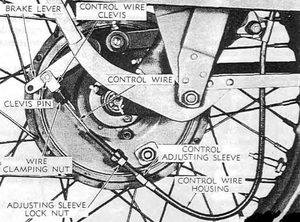
RA PD 310274 Figure 62—Front Brake Control and Adjusting Members
d. Adjusting Front Wheel Brake. End of brake hand lever must move freely about ¼ of its travel before meeting resistance of brake operation.
(1) Loosen adjusting sleeve lock nut and turn adjusting sleeve as necessary to attain correct free movement of hand lever.
(2) After correct hand lever adjustment is made, tighten adjusting sleeve lock nut.
e. Remove Brake Shoes.
(1) Remove front wheel (par. 125). After front wheel is removed, brake side cover and shoe assembly is accessible for shoe replacement.
(2) Remove brake shoes. Brake shoes and springs can be pried off pivot stud and freed from operating cam without removing springs.
f. Install Brake Shoes. Observe that brake shoes are made for upper and lower positions and are not interchangeable. Recess in end of shoe for pivot stud head determines position of shoe in assembly.
(1) Engage ends of springs in shoe holes from the inside before installing shoes in brake side plate.
(2) With shoes and springs assembled, install the shoes so that ends of shoes will slip over pivot stud and shaft operating cam.
(3) Install front wheel and brake assembly (par. 125).
(4) Loosen nut on brake shoe adjustable pivot stud and while applying pressure on brake hand lever, retighten pivot stud nut. This is to center brake shoes within the brake drum.
(5) After new or relined shoes have been installed, check brake hand lever and, if necessary, adjust the control wire (step d above).
Section XXI STEERING CONTROL
Paragraph
Forks98
Steering damper99
Handle bars100
Handle bar controls101
98. FORKS (figs. 63 and 64).
a. Either the spring fork can be removed and replaced, or the complete fork assembly (spring fork and rigid) can be replaced.
b. Remove Spring Fork (fig. 63).
(1) Support vehicle on rear stand.
(2) Remove the fork spring rod lock nuts (acorn‐type).
(3) Sit on front mudguard, or otherwise provide weight, to compress fork cushion (lower) springs. The spring rod large nuts can then be easily removed, freeing the upper recoil and upper bumper springs for removal.
(4) Remove front wheel (par. 125).
(5) Remove front mudguard (par. 104).
(6) Remove spring fork right and left side rocker plate studs. NOTE: Leave rigid fork rocker studs, with rockers, attached.
(7) Remove spring fork from vehicle.
c. Install Spring Fork.
(1) Place buffer springs and lower cushion springs on fork rods. Apply grease to rods. Pass fork rods up through rigid fork bracket. Bind lower end of spring fork to lower end of rigid fork with a strap or piece of heavy wire (fig. 64), to prevent forks from separating while compressing cushion springs.
(2) Install two bolts in the rigid fork brackets which mount the mudguard; then place a rod about 8 inches long on the brackets to provide a pry base for the leverage bar when compressing cushion springs (fig. 64). With a leverage bar about 18 inches long, anchored on top of the pry base rod and under the spring fork, lift upward to compress cushion springs sufficiently to install one of the rocker plates. Then install the other rocker plate (fig. 64). NOTE: Left side spring fork rocker plate stud has a button end which fits into notch in brake stabilizer plate.
(3) Install mudguard (par. 104).
(4) Install front wheel (par. 125).
(5) Install the two spring rod bushings. Install upper bumper springs and upper recoil springs on the fork rods, applying grease to rods.
(6) Remove blocks from under vehicle.
(7) Sit on mudguard to compress fork cushion (lower) springs. Tighten the two large spring rod nuts sufficiently to provide full thread for the spring rod lock nuts (acorn‐type). Install spring rod lock nuts and tighten.
(8) See that all nuts, bolts, and screws securing lamp bracket, mudguard, scabbard carrier, and ammunition carrier are tightened securely.
(9) Check front wheel brake for operation.
d. Remove Upper Recoil Springs and/or Upper Bumper Springs.
(1) Support vehicle on rear stand. Remove the fork spring rod lock nuts (acorn‐type).
(2) Sit on front mudguard, or otherwise provide weight, to compress fork cushion (lower) springs. The spring rod large nuts can then be easily removed, freeing the upper recoil and upper bumper springs for removal.
e. Install Upper Recoil Springs and/or Upper Bumper Springs.
(1) Apply grease to fork spring rods and install upper bumper springs.
(2) Install upper recoil springs over bumper springs on fork spring rods.
(3) Sit on front mudguard to compress cushion (lower) springs sufficiently to start on spring rod large nuts.
(4) Tighten both spring rod large nuts. Install and tighten the two spring rod (acorn‐type) lock nuts.
f. Remove and Install Lower Cushion Springs and/or Lower Buffer Springs. This operation calls for same procedure followed in removing and installing spring fork (steps b and c above).
g. Remove Complete Fork Assembly.
(1) Remove ammunition box carrier (par. 103).
(2) Remove scabbard carrier (par. 103).
(3) Remove front wheel (par. 125).
(4) Remove steering damper (par. 99).
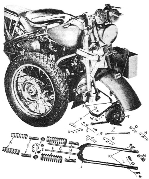
RA PD 315728 Figure 63—Spring Fork Disassembled
A—UPPER (RECOIL) SPRINGS
B—UPPER BUMPER SPRINGS
C—SPRING ROD LOCK NUTS (ACORN‐TYPE)
D—SPRING ROD BUSHINGS
E—LARGE SPRING ROD NUTS
F—LOWER CUSHION SPRINGS
G—SPRING RODS
H—LOWER BUFFER SPRINGS
J—SPRING FORK ASSEMBLY
K—ROCKER PLATE STUD NUTS AND LOCKS
L—RIGHT SIDE ROCKER PLATE STUD AND WASHER
M—LEFT SIDE ROCKER PLATE STUD (HAS BUTTON END) AND WASHER
N—AMMUNITION BOX CARRIER MOUNTING BOLT, WASHERS AND NUT
O—HEADLIGHT BRACKET AND MUDGUARD BOLT, WASHER AND NUT (LEFT SIDE)
P—FRONT AXLE, CASTLE NUT AND COTTER PIN
Q—SCABBARD CARRIER MOUNTING BOLT, WASHERS AND NUT
R—HEADLIGHT BRACKET AND MUDGUARD BOLT, MARKER LIGHT GABLE CLIP, WASHER AND NUT (RIGHT SIDE)
S—BRAKE SHACKLE BOLT, LOCK AND NUT
T—BRAKE AND SIDE COVER ASSEMBLY
U—MUDGUARD BRACKET MOUNTING LOCK, WASHER AND NUTS (RIGHT SIDE)
V—MUDGUARD AND RIGID FORK MOUNTING SCREWS, WASHERS AND NUTS
W—MUDGUARD BRACKET MOUNTING LOCK, WASHER AND NUTS (LEFT SIDE)
X—NOTCHES IN MUDGUARD BRACKETS FOR SPECIAL LOCKS
RA PD 3157288 Legend for Figure 63—Spring Fork Disassembled
(5) Remove front mudguard, after removing nuts and locks from rear rocker plate studs, two screws and nuts securing mudguard to rigid fork, and the two bolts mounting headlight bracket to mudguard. NOTE: Front mudguard blackout light wire connects to ignition and light switch and care must be exercised not to break this wire if it is not disconnected from the switch.
(6) Disconnect battery negative ground wire at frame connection. Remove blackout light (par. 114). Remove headlight, horn, and bracket assembly as one unit.
(7) Remove handle bar brake fittings and brake control wire housing from side of fork. Remove handle bars after removing handle bar bracket lock nut and cone lock plate. It is not necessary to disconnect spark and throttle control wire housings from frame. Unscrew fork upper adjusting cone from fork stem, freeing fork assembly to be removed from frame head. NOTE: Steering head ball bearings are loose (not in retainers) in upper and lower frame head bearing cups. Take care not to lose balls.
h. Install Fork Assembly. With vehicle on rear stand, and front end up by blocking under frame loop or skid plate, proceed with installing fork assembly, as follows:
(1) Thoroughly clean upper and lower frame head bearing cups and pack with general purpose grease No. 2, installing fifteen 5⁄16–inch ball bearings in each cup. Work grease thoroughly in between balls.
(2) See that lower fork stem cone is clean and in place, pass fork stem up through frame head, turning on upper adjusting cone. Do not try to adjust bearing cone as yet.
(3) Install handle bars by locating mounting bracket on ends of fork sides and center stem, making sure that spark and throttle control wire housings are in place.
(4) Adjust upper fork stem adjusting cone so that there is no perceptible shake in head bearings when handle bars are worked up and down, and fork does not bind when turned to right and left extremes.
(5) Install cone lock plate by engaging pin in one of the cone notches.
(6) Install lock nut on stem and tighten securely. NOTE: Check head bearing play, as tightening lock nut sometimes makes head bearing too tight. Readjust if necessary.
(7) Attach handle bar brake fittings and brake control wire housing to side of fork.
(8) Reinstall headlight, horn, and bracket assembly. Connect wires (per wiring diagram fig. 73) before front mudguard is reinstalled. Install blackout light (par. 114). Reconnect battery negative ground wire to frame ground connection.
(9) Install steering damper (par. 99).
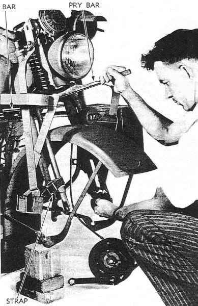
RA PD 310266 Figure 64—Compressing Cushion Springs for Spring Fork Assembly
(10) Install front mudguard. Attach two screws, washers, and nuts for rigid fork mounting and two bolts, washers, and nuts for headlight bracket mounting. Fit right and left mudguard brace clip locks to right and left side rocker plate studs respectively. Do not put on nuts until after installing ammunition box carrier and scabbard carrier.
(11) Install front wheel (par. 125).
(12) Install scabbard carrier and ammunition box carrier (par. 103).
(13) Check lights, horn, spark control, throttle control, front brake control, steering damper control, and steering head bearing for freedom without binding.
i. Remove Rocker Plate Studs. Studs and/or rocker plates can be removed and installed in the same operation. In removing and installing studs, remove only one fork rocker plate at a time, leaving the other plate attached to opposite side fork ends to hold fork springs in compressed position. This will eliminate necessity of compressing fork springs to fit rocker plates on studs.
(1) Remove front wheel (par. 125).
(2) Remove nuts and locks from rocker plate studs on right side of vehicle. This releases gun scabbard carrier and mudguard stay clip. NOTE: Remove the large nut which secures the long stud to rigid fork.
(3) Drive out studs from fork ends, releasing rocker plate.
(4) Install studs and rocker plate before removing studs from left side of vehicle.
j. Install Rocker Plate Studs. Apply grease to studs and insert in rocker plate, then install large flat washers on studs before mounting this assembly on fork ends. Make sure that short stud is in front position, and that long stud is in rear position for the rigid fork.
(1) Drift studs (with plate assembly) into fork end holes from the inside.
(2) Install special nut lock (with half round hole) on front stud and turn stud as necessary to make lock “cup” over end of fork. Install and tighten stud nut and bend up end of lock for security. Place lock washer over long stud and install thick nut, securely tightening it.
(3) Attach end of gun scabbard carrier and mudguard brace clip with special lock to long stud, replacing washer and nut.
(4) After right side rocker plate and/or studs have been installed, remove and install studs and/or plate on left side of vehicle following same step‐by‐step procedure as above. The exceptions will be ammunition box carrier instead of scabbard carrier; also, the left side front stud is special, having a “button” end.
(5) Install front wheel (par. 125).
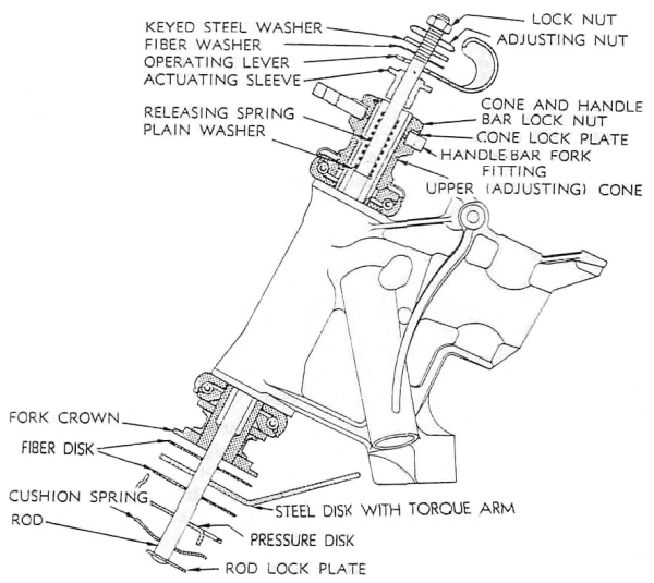
RA PD 310276 Figure 65—Steering Damper Assembly
99. STEERING DAMPER (fig. 65).
a. Remove (fig. 65).
(1) Remove front wheel (par. 125).
(2) Remove front mudguard (par. 104).
(3) Remove lock nut from steering damper rod, then remove upper end parts in the following order: adjusting nut, keyed steel washer, fiber washer, operating lever, and actuating sleeve. This entire assembly is located in the central part of the handle bar mounting bracket.
(4) Steering damper rod, cushion spring, pressure disk, fiber disk, and steel disk assembly can now be withdrawn (downward) from fork stem hole.
b. Install (fig. 65). Before installing steering damper, make sure that the parts are in correct order on the lower end of the rod before passing rod up through hole in fork stem. Check parts and order of assembly.
(1) Assemble parts on rod end (fig. 65), making sure that the bent down lip of the steel pressure disk engages with notch in end of the rod lock plate.
(2) Pass rod with its lower end assembly up through hole in fork stem, turning steel pressure disk to front position so that “bent‐up” lip engages with notch in front side of rigid fork crown, at the same time engaging curved end of steel disk torque arm in slot in underside of frame head. Maintain pressure against end of rod to keep lower disks in order while assembling upper rod end parts.
(3) Install upper rod end assembly in the following order: Small plain washer, releasing spring, adjusting sleeve screws into end of fork stem, operating lever registers on the adjusting sleeve, fiber washer, keyed steel washer registers in rod slot, large adjusting nut, and lock nut.
(4) Turn actuating sleeve all the way into fork stem and then back it out (up) ½ turn or more. Register the operating lever on flat of actuating sleeve, and see that lever has full movement to the left without bottoming sleeve in the fork stem.
(5) Adjust steering damper by setting adjusting (large) nut so that operating lever must be moved nearly straight back from the free (left‐side) position, before damper takes noticeable effect (applies friction to movement of the handle bars). Hold large adjusting nut and tighten the small lock nut.
(6) Install front mudguard (par. 104).
(7) Install front wheel (par. 125).
100. HANDLE BARS.
a. Remove Complete Assembly. If vehicle is equipped with handle bar windshield and rear view mirror, remove these accessories before starting to remove handle bar assembly.
(1) Disconnect throttle control wire at carburetor lever, and spark control wire at timer lever.
(2) Release spark control wire housing clip at front cylinder base bolt (near timer). Also release housing from frame clip on left side of vehicle. Release throttle control wire housing clip, located at tank, lower front connection bolt.
(3) Remove front brake hand lever fittings from handle bars. Also release brake control wire housing at handle bar clamp.
(4) Disconnect battery negative ground wire at frame connection and wires at headlight. Headlight must be removed for access to the two terminal screws (fig. 73).
(5) Disconnect horn wire leading to handle bars and red wire (terminal No. 17, fig. 73) leading to handle bars.
(6) Remove steering damper rod upper end fittings in the following order: Lock nut, adjusting nut, keyed steel washer, fiber washer, operating lever, and operating sleeve (screws into end of fork stem). Removal of these parts gives access to handle bar lock nut. Remove handle bar lock nut and cone lock plate.
(7) Loosen handle bar bracket‐fork end pinch bolts. Handle bars are now free to be drifted off ends of fork sides and center stem.
(8) Remove handle bar windshield apron spring guard after handle bars are removed from vehicle.
b. Install Complete Assembly. If vehicle is equipped with handle bar windshield and rear view mirror, attach these accessories after handle bar assembly is installed.
(1) Attach windshield apron spring guard to handle bar bracket. Do not tighten bolt nut until after handle bars are installed.
(2) Start handle bar bracket holes over ends of fork, seeing that spark control wire housing is on right side of frame head: then drive handle bars onto fork ends, using a rawhide mallet, or a hammer and wood block.
(3) To install cone lock plate, enter registering pin through hole in handle bars and engage notch in the adjusting cone. Install and tighten handle bar lock nut securely. CAUTION: When tightening this nut, always make sure that register (shoulder) of nut enters hole in lock plate and handle bars.
(4) Check adjustment of head bearing. The fork must turn freely but without perceptible shake. Readjust head cone to obtain proper bearing adjustment if necessary.
(5) Tighten handle bar bracket‐fork end pinch bolts.
(6) Position windshield apron guard so that it clears fork springs. Securely tighten mounting bolt nut.
(7) Install steering damper upper end fittings (fig. 65). Make sure that lower end disks and plates are properly engaged. Adjust (par. 99).
(8) Connect handle bar wires to terminal plate, horn, and headlight. Consult wiring diagram (fig. 73). Install headlight. Adjust beam and secure mounting nut (par. 114). Connect battery negative ground wire to frame connection.
(9) Check operation of lights and horn, tactical situation permitting.
(10) Attach front brake hand lever fittings to left handle bar. Secure control wire housing in handle bar clamp, just ahead of housing oiler. Check front brake for correct operation and, if necessary, adjust (par. 97).
(11) Pass spark control wire housing along left side of frame front tube, between cylinders (under carburetor) to position housing end clamp on cylinder stud near timer. Secure clamp under cylinder stud nut. Secure wire cable under clamp on left side of frame front tube, with white paint mark slightly ahead of clamp front edge. Engage end of spark control wire in timer lever and adjust spark control (par. 88).
(12) Pass throttle control wire housing along right side of frame front tube and over top of front cylinder head to reach carburetor connection. Install tank (lower front) mounting bolt to secure wire housing clamp. See that white paint mark on wire housing is slightly ahead of clamp, then secure bolt nut on left side of vehicle. Engage end of throttle control wire in throttle lever and adjust (par. 69).
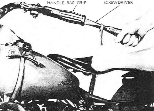
RA PD 310282 Figure 66—Removing Handle Bar Grip Sleeve Retaining Nut
101. HANDLE BAR CONTROLS (figs. 66 and 67).
a. Construction of the throttle and spark controls is the same, thus replacing a control wire or wire housing follows the same general procedure up to the point where control adjustment is made. Handle bar grip sleeves (spirals) are interchangeable.
b. Remove Throttle Control Wire (fig. 67).
(1) Disconnect control wire at throttle lever connection.
(2) Insert blade of a large, square‐shank screwdriver through hole in end of grip and turn out end nut by using a wrench on the shank of the screwdriver (fig. 66). Sometimes this nut is difficult to remove. In this case, insert punch into the slot in the nut and strike punch two or three sharp blows to “free” nut in handle bar end threads. Remove nut as above. NOTE: Nut remains inside the grip and is removed with the grip and spiral sleeve assembly.
(3) Remove grip and spiral assembly from handle bars. Control wire and working parts are now accessible.
(4) Remove plain roller from pin. Remove roller block from pin. Remove pin from plunger.
(5) Pull plunger with wire attached out of handle bar end. Remove hexagon head screw which secures wire to plunger. NOTE: If wire is broken, remove other half from housing at carburetor connection end.
(6) Remove any rust, dirt, or gum from grip spiral, handle bar end, wire plunger, and inside of handle bar where plunger operates.
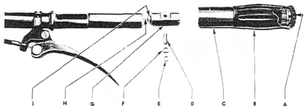
A—END NUT.
B—GRIP.
C—GRIP SLEEVE ASSEMBLY.
D—ROLLER PIN.
E—ROLLER.
F—ROLLER BLOCK.
G—PLUNGER.
H—CONTROL WIRE.
I—WIRE RETAINING NUT.
RA PD 310263 Figure 67—Handle Bar Grip and Wire Control, Disassembled
c. Install Throttle Control Wire (fig. 67).
(1) Pass hollow screw over control wire with threaded end of hollow screw facing button on end of wire. Install screw in end of plunger. Securely tighten screw.
(2) Apply grease or engine oil to control wire and insert end into control wire housing.
(3) Apply grease to plunger and push plunger and wire into handle bar until plunger pin hole is exposed in handle bar slot. Work plunger or turn it within handle bar so that pin hole and flat side are upward and are centered in slot; then insert roller pin into plunger hole, roller block (with flat sides), and roller in order named. Apply grease to plunger pin and roller and to outside of handle bar end.
(4) Install grip and spiral assembly by engaging plunger roller in spiral opening in end of grip sleeve. Grip spiral sleeve nut can best be started without danger of cross threading, by holding grip assembly back slightly while starting nut in handle bar end. This squares nut with end of grip sleeve, alining threads. Securely tighten nut with screwdriver and wrench.
(5) Connect control wire at throttle lever connection. Adjust control (par. 69).
d. Remove Spark Control Wire (fig. 67). Disconnect control wire at timer lever and follow procedure outlined under step b above.
e. Install Spark Control Wire (fig. 67). Follow procedure outlined under step c above, then connect control wire at timer lever and adjust control (par. 88).
f. Remove and Install Control Wire Housings. Remove either control wire housing after following procedure outlined above (step b), then remove set screw on under side of handle bar, just ahead of grip sleeve shoulder. NOTE: Set screw for spark control wire housing is located under headlight dimmer switch. After set screw is removed and housing freed from attaching clamps, housing can be pushed out through end of handle bar.
(1) When installing control wire housings, see that housing end is secured in handle bar with set screw, and that housing is correctly attached to vehicle clamps.
(2) Install control wire and grip (step c above) and adjust controls: spark (par. 88), throttle (par. 69).
Section XXII SHEET METAL AND EQUIPMENT
Paragraph
Chain guards102
Carriers103
Mudguards104
Battery box105
Tool box106
Tanks107
Stands108
Saddle post109
Safety guards110
Skid plate111
102. CHAIN GUARDS.
a. Remove Outer Front Chain Guard (figs. 68 and 69).
(1) Remove nut and washer which secures center of chain guard and skid plate left‐side support bracket.
(2) Loosen skid plate support bracket lower bolt and nut and remove bracket from stud.
(3) Loosen the nut which secures footboard rear stud to sidebar, then remove nut which secures footboard front stud to sidebar. Pull front end of footboard away from sidebar so that stud will clear end of safety guard.
(4) Remove extended nut which secures sidebar to frame front support rod.
(5) Disconnect clutch control cable end at clutch foot pedal by removing cotter pin and plain washer from stud.
(6) Left side footboard, sidebar, and clutch foot pedal assembly can now be removed. If rear end of sidebar is lowered, the front end will clear end of safety guard.
(7) Remove cotter pin, nut, spring, washer, and bolt from chain guard rear mounting. Outer front chain guard can now be removed, exposing engine sprocket, front drive chain, and clutch assembly.
b. Install Outer Front Chain Guard.
(1) Locate outer front chain guard on center support stud (frame rear support rod end). Line up rear mounting bracket with frame bracket.
(2) Install bolt, washer, spring, nut, and cotter pin to secure rear mounting.
(3) Install footboard, sidebar, and clutch foot pedal assembly on frame support rod ends.
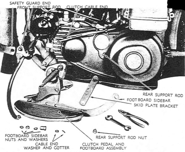
RA PD 310264 Figure 68—Left Footboard Assembly Removed
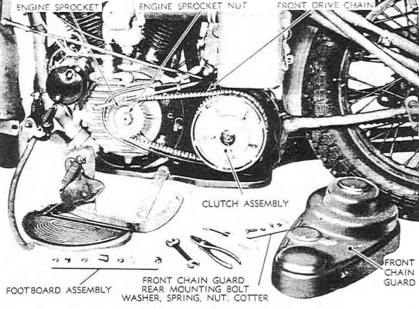
RA PD 315729 Figure 69—Outer Front Chain Guard Removed
(4) Attach front end of sidebar. Install extended nut and lock washer to secure front sidebar and support rod mounting.
(5) Install skid plate support bracket on support rod (in center of chain guard), tightening nut on bolt. Install nut and lock washer which secure skid plate bracket and chain guard on rear support rod. Tighten nut.
(6) Pull front end of footboard away from sidebar so that hole in end of safety guard lines up with hole in sidebar, then pass footboard stud through both pieces, installing washer and securing stud nut. Tighten footboard rear stud nut.