Chapter XXXVII · WIRES AND WIRE CALCULATIONS
Reading edition
The wireman who is called upon to plan and install a system of wiring will find it necessary first to have a knowledge of the various kinds of wire so as to select the one best suited for the work, and to be able to make simple calculations in order to determine the proper sizes of wire for the various circuits.
Wires are generally made of circular cross section. The process of manufacture consists in drawing the material through steel dies, when its properties permit this treatment. In the case of some substances, as for instance, tin and lead, difficulties arise in the drawing process, and these are therefore "squirted."
The metals most extensively used for wires are copper and iron; German silver, tin and lead are also employed, but only at points where it is desirable to have a comparatively high resistance in the circuit.
Copper Wire.—Copper is used in nearly all cases of wiring because it combines high electrical conductivity with good mechanical qualities and reasonable price. In conductivity it is only surpassed by silver, but the cost of the latter of course prohibits its use for wiring purposes.
Copper wire is used for electric light and power lines, for most telephone and some telegraph lines, and for all cases where low resistance is required at moderate cost.
Hard drawn copper wire is ductile, and has a high tensile strength; these properties allow it to be bent around corners and drawn through tubes without injury.
Pure annealed copper has a specific gravity of 8.89 at 60° Fahr. One cubic inch weighs .32 pound; its melting point is about 2,100° Fahr.
Good hard drawn copper has a tensile strength of about three times its own weight per mile length. Thus, a number 10 B. & S. gauge copper wire, weighing 166 lbs. per mile, will have a breaking strength equal to approximately 3 × 166 = 498 lbs.
Iron Wire.—This kind of wire is largely used for telegraph and telephone lines, although it is rapidly being replaced by copper in long lines.
There are three grades of iron wire:
1. Extra best best (E. B. B.) which has the highest conductivity and is the nearest to being uniform, in quality, being both tough and pliable;
2. Best best (B. B.), which varies more in quality, is not so tough, and is lower in conductivity. It is frequently sold as E. B. B.;
3. Best (B.), which is the poorest grade made, being more brittle, and lowest in conductivity. Iron wire should be well galvanized.
German Silver Wire.—German silver is an alloy consisting of 18 to 30% nickel, and the balance about four parts copper to one part zinc. It is very largely used as a resistance material in making resistance coils, and is sold in the form of wire, and strip. The resistance of this wire varies with its composition.
The resistance of the 18% alloy at 25° C. is 18 times that of copper, and of the 30% alloy about 28 times that of copper.
The safe carrying capacity of the wire in spirals in open air for continuous duty is such that the circular mils per ampere varies from about 1,500 in No. 10 wire to about 475 in No. 30. For intermittent duty the capacity is twice as great.
Standard of Copper Wire Resistance.—Matthiessen's standard for resistance of copper wire is as follows: A hard drawn copper wire one meter long, weighing one gramme, has a resistance of .1469 B. A. unit at 32° Fahr. Relative conducting power: silver, 100; hard or un-annealed copper, 99.95; soft or annealed copper, 102.21.
A committee of the Am. Inst. Electrical Engineers recommends the following form of Matthiessen's standard, taking 8.89 as the specific gravity of pure copper: A soft copper wire one meter long and one millimeter in diameter has an electrical resistance of .02057 B. A. unit at 0°C.2 From this the resistance of a soft copper wire one foot long and .001 in. in diameter (mil-foot) is 9.72 B. A. units at 0°C.
For every degree Fahr., the resistance of copper wire increases .2222%. Thus a piece of copper wire having a resistance of 10 ohms at 32°, would have a resistance of 11.11 ohms at 82°.
Relative Conductivity of Different Metals and Alloys. (According to Lazare Weiler.)
Pure silver 100
Pure copper 100
Alloy, ½ copper, ½ silver 86 .65
Telephonic siliceous bronze 35
Pure zinc 29 .9
Brass with 35% zinc 21 .5
Swedish iron 16
Pure platinum 10 .6
Copper with 10% nickel 10 .6
Pure lead 8 .88
Pure nickel 7 .89
Phosphor-bronze, 10% tin 3 .88
Conductors.—Copper is used more than any other metal for transmitting electrical energy, and for interior wiring it is used exclusively. Copper conductors should be of the highest commercial conductivity, not less than 97%.
For conductors up to sizes as large as No. 8 B. & S. gauge, single conductors may be used, but for larger sizes the necessary conductivity should be obtained by conductors made up of strands of smaller wires. The size of these strands depend upon the size of the conductors and the conditions under which they are to be used.
Where conductors are very large (as for instance dynamo leads), and where it is essential that they should be as flexible as possible, strands as small as No. 20 or 22 B. & S. gauge may be used.
Conductors for flexible cords, pendants, fixtures, etc., should also consist of very fine strands, so that they may be perfectly pliable and flexible.
The individual strands for instance, for a No. 16 B. & S. gauge flexible cord should be as fine as No. 30.
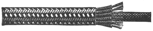
Fig. 807.—Elevator cable for annunciators. This type of cable is designed for connecting the movable elevator car with the signal buttons upon the different floors, and is constructed so as to secure strength and flexibility.
Covered Conductors.—For most conditions of service, wires are protected with an insulating covering. Wires used in interior circuits should have a covering which shall act both as an electrical insulator and as a mechanical protection. In some instances, however, the insulating qualities are of secondary importance.
The various forms of covering now in use commercially for wires are:
1. Rubber; 2. Weather proof; 3. Slow burning; 4. Slow burning weather proof; 5. Armoured.
Rubber Covered Conductors.—This class of conductor consists of a tinned copper wire with a rubber covering, protected by an outside braiding of cotton saturated with a preservative compound.
Ques. What are the advantages of rubber insulation for conductors?
Ans. It is waterproof, flexible, fairly strong, and has high insulating qualities.
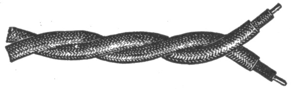
Fig. 808.—Rubber insulated telephone and telegraph wires. The inner coat of rubber should be free from sulphur or other substances liable to corrode the copper.
Ques. What are the disadvantages of rubber insulation?
Ans. It deteriorates more or less rapidly and is quickly injured by temperatures above 140° Fahr.
Ques. For what service are rubber covered conductors adapted?
Ans. For interior wiring.
Ques. Is pure rubber used?
Ans. No. The covering should be made from a compound containing from 20 to 35 per cent. of pure rubber.
It would be difficult to place pure rubber on a wire, and moreover a covering made of pure rubber would not be durable and would deteriorate very rapidly, particularly at temperatures above 120° Fahr. Accordingly, it is mixed with other materials, such as French chalk, silicate of magnesia, sulphur, red lead, etc.
Weather Proof Conductors.—In this class of conductor, the wire is protected from the weather by a waterproof covering, consisting usually of braided cotton of two or three thicknesses saturated with a moisture resisting insulating compound.
Ques. Where are weather proof conductors used?
Ans. In places subject to dampness, such as cellars, tunnels, open sheds, breweries, etc.

Fig. 809.—Twisted weather proof wires. The insulation consists of two or three thicknesses of braided cotton saturated with a moisture resisting insulating compound.
Ques. What are the advantages of weather proof conductors?
Ans. The insulation is cheap, very durable, and does not deteriorate unless exposed to high temperatures such as will melt the compound.
Ques. State the disadvantages.
Ans. The covering is more or less inflammable and is not very efficient as an insulator.
Ques. What precaution should be taken in using weather proof conductors?
Ans. On account of the inflammable character of the covering, care should be taken in wiring at points where any considerable number of conductors are brought together, or where there is much woodwork or other combustible material.
Ques. For what use are weather proof conductors especially adapted?
Ans. For outside wiring where moisture is certain and where fireproof quality is not necessary.
Obviously conductors of this class should not be used in conduits, nor in fact, in any way except exposed on glass or porcelain insulators.
Slow Burning Wire.—This class of conductor is defined as: one that will not carry fire. The covering consists of layers of cotton or other thread, all the interstices of which are filled with the fireproofing compound, or of material having equivalent fire resisting and insulating properties. The outer layer is braided and specially designed to withstand abrasion. The thickness of insulation must not be less than that required for slow burning weather proof wire and the outer surface must be finished smooth and hard.—Underwriters' requirements.

Fig. 810.—Slow burning wire, formerly known as Underwriter's Wire. The insulation is triple braided, saturated with a white fireproof compound. Solid conductor.
Ques. Where should slow burning wires be used?
Ans. In hot dry places, where ordinary insulations would be injured, and where wires are bunched, as on the back of a large switchboard or in a wire tower.
A slow burning covering is considered good enough when the wires are entirely on insulating supports. Its main object is to prevent the copper conductors coming into contact with each other or anything else.
Ques. What must be done before using weather proof wire?
Ans. Permission to use the wire must first be obtained from the local Inspection Department.
Slow Burning Weather Proof Wire.—The covering of this type wire is a combination of the underwriters and weather proof insulations. The fireproof coating comprises a little more than half of the total covering. When the fireproof coating is placed on the outside, the wire is called "slow burning weather proof."

Fig. 811.—Slow burning weather proof wire. The insulation is composed of two braids thoroughly saturated with a fire proof composition, over which is a highly polished weather proof third braid. This wire was formerly known as "fire and weather proof" wire.
Ques. How does slow burning weather proof wire compare with weather proof wire?
Ans. It is less inflammable and less subject to softening under heat.
Ques. Where should slow burning weather proof wire be used?
Ans. In places where the wires are to be run exposed and where moisture resisting quality is desired, also where at the same time it is desirable to avoid an excess of inflammable covering.
Ques. How should it be installed?
Ans. It should be set on glass or porcelain insulators.
Miscellaneous Insulated Conductors
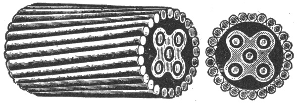
Fig. 812.—Armoured submarine cable. This type of cable is insulated with a rubber compound containing not less than 30% of pure Para rubber. The following specifications have been adapted by various telegraph companies and the United States Government for general use.
No. of Conductors Gauge of Conductors (B. & S.) No. of Armour Wires Gauge of Armour Wires B. W. G. Outside Diameter (inch) Weight per 1,000 Feet
1 14 12 8 ⅞ 1,150
2 14 16 8 1 31/32 1,675
3 14 14 6 1¼ 2,400
4 14 16 6 1 5/16 2,750
5 14 19 6 1 ⅜ 3,100
6 14 21 6 1 ½ 3,500
7 14 21 6 1 ½ 3,600
10 14 22 4 1 ⅞ 4,600
NOTE.—The above specifications refer only to river and harbor cables. Ocean cables are of an entirely different character, and consist of "shore end," "intermediate" and "deep sea" types.

Fig. 813.—Gas engine ignition cable. This is a special cable made to stand the hard service necessary on automobiles. The conductor is composed of 36 strands of No. 27 tinned copper wire, equal to No. 14 in capacity, which gives it necessary flexibility. About this conductor are woven two layers of cotton thread. Over this are woven, in opposite directions, several layers of specially prepared tape which has been given two coatings of fine insulating varnish. Two strong braids of cotton form the outside covering, and each of these different braids is passed through a bath of insulating liquid and baked in a steam heated oven. With three layers of tape the cable will stand a test of 18,000 to 20,000 volts, and with five layers, 30,000 volts.
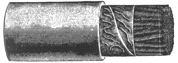
Fig. 814.—Paper insulated lead encased telephone cable.
Ques. For what service is slow burning weather proof wire not suited?
Ans. It is not adapted to outside work.
Safe Carrying Capacity of Wire.—All wires will heat when a current of electricity passes through them. The greater the current or the smaller the wire, the greater will be the heating effect. Large wires are heated comparatively more than small wires because the latter have a relatively greater radiating surface.

Fig. 815.—Pothead wires. The standard wire for pothead work is either No. 19, 20 or 22 B. & S. gauge, either single conductor or twisted pair, insulated to a diameter of 3/32 inch over rubber, without any outer braid or protection. In the case of twisted pairs one conductor is usually made of a differently colored rubber than the other, so as to distinguish between them.
The temperature of a wire increases approximately as the square of the current, and inversely as the cube of the diameter of the wire.
The elevation in temperature of a wire carrying a current represents so much lost energy.
From these considerations it must be clear that it is important not to overload conductors in order to secure efficient working, and to avoid risk of fire on inside installations.
The Board of Underwriters specifies that the carrying capacity of a conductor is safe when the wire will conduct a certain current without becoming painfully hot.
In the following table of carrying capacity, prepared by the underwriters, a wire is assumed to have a safe carrying capacity when its temperature is not increased by the given current over 30° Fahr. above that of the surrounding air.
SAFE CARRYING CAPACITIES OF WIRES (Maximum amperes allowed by the Underwriters.)
Brown and Sharpe Gauge Circular mils Rubber insulation ——— Amperes Other insulations ——— Amperes
18 1,624 3 5
16 2,583 6 8
14 4,107 12 16
12 6,530 17 23
10 10,380 24 32
8 16,510 33 46
6 26,250 46 65
5 33,100 54 77
4 41,740 65 92
3 52,630 76 110
2 66,370 90 131
1 83,690 107 156
0 105,500 127 185
00 133,100 150 220
000 167,800 177 262
0000 211,600 210 312
200,000 200 300
300,000 270 400
400,000 330 500
500,000 390 590
600,000 450 680
700,000 500 760
800,000 550 840
900,000 600 920
1,000,000 650 1,000
1,100,000 690 1,080
1,200,000 730 1,150
1,300,000 770 1,220
1,400,000 810 1,290
1,500,000 850 1,360
1,600,000 890 1,430
1,700,000 930 1,490
1,800,000 970 1,550
1,900,000 1,010 1,610
2,000,000 1,050 1,670
The lower limit is specified for rubber covered wires to prevent gradual deterioration of the high insulations by the heat of the wires, but not from fear of igniting the insulation. The question of drop is not taken into consideration in the table on page 731.
The carrying capacity of Nos. 16 and 18 B. & S. gauge wire is given, but no smaller than No. 14 is to be used, except as allowed under rules for fixture wiring.—Underwriters' Rules.
Circular Mils.—The unit of measurement in measuring the cross sectional area of wires is the circular mil; it is the area of a circle one mil (.001 in.) in diameter.
The area of a wire in circular mils is equal to the square of the diameter in mils.
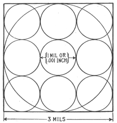
Fig. 816.—Diagram illustrating circular mils. The circular mil is used as a unit of cross sectional area in measuring wires. It is equal to the area of a circle .001 in. diameter; its value is .0000007854 square inch. In the figure the sum of the areas of the nine small circles equals the area of the large circle. This is evident from the following: Take the diameter of the small circles as unity, then the diameter of the large circle is three. Hence, the sum of the area of the small circles × (¼ π × 12) × 9 = .7854 × 9 = 7.0686; area of the large circle = ¼ π × 32 = .7854 × 9 = 7.0686. Therefore since the area of the large circle equals the sum of the areas of the small circles, the area of a wire in circular mils is equal to the square of its diameter expressed in mils.
Thus a wire 2 mils in diameter (.002 in.) has a cross sectional area of 2 × 2 = circular mils. Accordingly to obtain the area of a wire in circular mils, measure its diameter with a micrometer which reads directly in mils or thousandths of an inch, and square the reading.
The circular mil (abbreviated C.M.) applies to all round conductors, and has a value of .7854 times that of the square mil, that is, 1 circular mil = .7854 square mil. If the diameter be expressed as a fraction of an inch, as for instance 1/3 in., the circular mil area may be found as follows: Reduce the fraction 1/3 to the decimal of an inch, multiply the result by 1,000 to express the diameter in mils, and square the diameter so expressed, thus: 1/3 = 1,000 ÷ 3 = .333. .333 × 1,000 = 333 mils; 333 × 333 = 110,889 circular mils.
The diameter of any wire may be found when its circular mil area is known by extracting the square root of the circular mil area.
Square Mils.—For measuring conductors of square or rectangular cross section, such as bus bars, copper ribbon, etc., the square mil is used. A square mil is the area of a square whose sides are one mil (.001 in. long) and is equal to .001 × .001 = .000001 square inch.
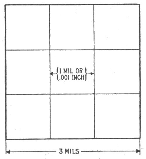
Fig. 817.—Diagram illustrating square mils. A square mil is a unit of area employed in measuring the areas of cross sections of square or rectangular conductors. It is equal to .000001 square inch. One square mil equals 1.2732 circular mils. The figure shows an area of nine square mils; this is equal to 9 × 1.2732 = 11.4588 circular mils.
EXAMPLE.—A copper ribbon for a field coil measures ⅝ inch by ⅛ inch. What is its area in square mils? What is its area in circular mils?
⅝ = .625 in., or 625 mils; ⅛ = .125 in., or 125 mils.
Area in square mils = 625 × 125 = 78,125.
Area in circular mils={78,125 ÷ .7854 }{or 78.125 × 1.2732} = 99,469.
Mil Foot.—This unit is used as a basis for computing the resistance of any given wire. A mil foot means a volume one mil in diameter and one foot long.
The resistance of a wire of commercially pure copper one mil in diameter and one foot long is taken as a standard in calculating the resistance of wires, and has been found to be equal to 10.79 ohms at 75° Fahr.
The calculation is made according to the following rule:
The resistance of a copper wire is equal to its length in feet, multiplied by the resistance of one mil foot (10.79 ohms) and divided by the number of circular mils, or the square of its diameter.
Expressed as a formula:
resistance in ohms = length of wire in ft. × 10.79 circular mils . . . . (1)
EXAMPLE. What is the resistance of a copper wire 1,500 feet long and having a transverse area of 10,381 circular mils?
Substituting these values in formula (1)
resistance= 1,500 × 10.79 10,381 =1.559 ohms.
The transverse area of a copper wire is found by multiplying the resistance of a mil foot (10.79) by its length in feet and dividing the result by its resistance in ohms.
This is obtained directly from the formula (1) by solving the equation for circular mils, thus:
circular mils = length of wire in ft. × 10.79 resistance in ohms . . . . (2)
EXAMPLE. What is the circular mil area of a wire 1,500 feet long and having a resistance of 1.559 ohms?
Substituting the values in equation (2)
circular mils = 1,500 × 10.79 1.559 = 10,381
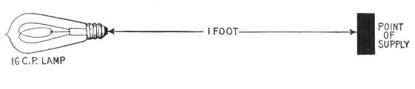
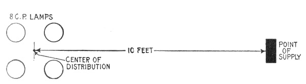
Figs. 818 and 819.—Diagrams illustrating the meaning of the term lamp foot, and how to apply it in calculating a circuit. As defined, one 16 candle power lamp at a distance of one foot from the fuse block or point of supply is called a lamp foot; this is equivalent to one 8 candle power lamp at a distance of 2 feet, or one 32 candle power lamp one-half foot from the fuse block. In fig. 819, there are four 8 candle power lamps, and the distance to center of distribution is 10 feet. The circuit then contains 4 ÷ 2 × 10 = 20 lamp feet.
Lamp Foot.—This unit facilitates laying out wiring and calculating the drop. A lamp foot is defined as one 16 candle power lamp at a distance of one foot from the point of supply. Accordingly the number of lamp feet in any circuit is equal to the number of 16 candle power lamps (or equivalent in other sizes) in the circuit multiplied by the distance in feet from the fuse block to the center of distribution.
When no point is specified, the feet are always measured from the supply point to the center of distribution. When other than 16 c.p. lamps are in the circuit they must be reduced to 16 c.p. lamps. Thus two 8 c.p. lamps would be counted one 16 c.p. lamp, one 32 c.p. lamp would be counted two 16 c.p. lamps, etc.
Ampere Foot.—From the foregoing explanation of lamp foot, the significance of ampere foot is easily understood—the two terms are in fact self-defining.
An ampere foot may be defined as the product of one ampere multiplied by one foot.
The unit ampere foot is used in figuring motor circuits or currents designed to carry a mixed load.
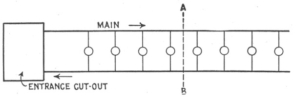
Fig. 820.—The center of distribution of a circuit coincides with the geometrical center of the group of lamps when the lamps are of uniform size and spaced equal distances apart. The center of distribution is here indicated by the dotted line A B.
The ampere feet of a main are found by multiplying the maximum load in amperes by the distance from the fuse block to the electrical center of the load.
Thus if the center of distribution be 50 feet from the fuse block and the maximum load is 9 amperes, the number of ampere feet is equal to 9 × 50 = 450.
Electrical Center of Distribution.—The electrical center of a circuit depends upon the distances between the lamps and the fuse block; also the relative sizes of the lamps.
It may be defined as the sum of the lamp feet for each section divided by the number of 16 candle power lamps in the circuit.
If the lamps be of uniform capacity, and placed at equal distances apart, the center of distribution will coincide with the geometrical center of the group of lamps. However, if the lamps vary in size, and be irregularly spaced, the electrical center will not coincide with the geometrical center unless the lamps be symmetrically arranged so as to compensate for the difference in sizes and spacing.
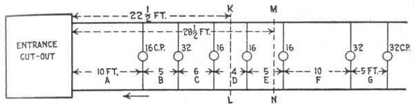
Fig. 821.—Diagram of an irregular circuit illustrating method of finding the center of distribution. Rule: Divide the sum of the lamp feet for each section by the number of 16 candle power lamps or equivalent in the circuit; the quotient gives the distance in feet from the fuse block to the center of distribution.
In such cases, as shown in fig. 821, the electrical center can be determined by adding together the lamp feet of the several sections A, B, C, etc., of the main and dividing the result by the 16 c.p. units. Thus the lamp feet of
Section A = 10 lamps × 10 feet = 100
" B = 9 " × 5 " = 45
" C = 7 " × 6 " = 42
" D = 6 " × 4 " = 24
" E = 5 " × 5 " = 25
" F = 4 " × 10 " = 40
" G = 2 " × 5 " = 10
which added together gives a total of 286 lamp feet.
This when divided by the ten 16 c.p. units comprising four 16 c.p. lamps and three 32 c.p. lamps, gives a little over 28½ feet as the distance from the fuse block to the center of distribution, the position of which is shown by the line M N in fig. 821, while that of the geometrical center is shown by the line K L.
When the center of distribution is at a considerable distance from the supply circuit, and it becomes advisable to divide the wiring into two distinct elements—a feeder and one or more mains, the junction of the feeder and the mains should be located at the electrical center of the mains whenever possible. When this is done, it is obvious that the wire size of only one half the main needs to be calculated, as both halves of the main are identical.
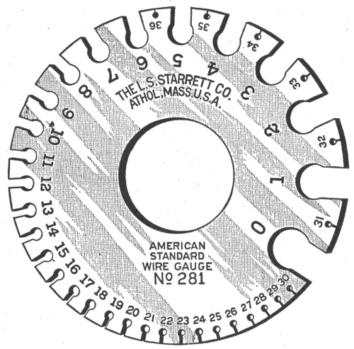
Fig. 822.—Brown and Sharpe (B. & S.), or American Standard wire gauge. This gauge was adopted by the brass manufacturers Jan., 1858. The cut is full size, and therefore, shows the actual sizes corresponding to the gauge numbers.
Wire Gauges.—For the purpose of facilitating the measurement of wire, a number of gauges have been designed by various wire manufacturing concerns. The principal gauges used in the United States are the American or Brown & Sharp's gauge; the English standard or Birmingham gauge; Washburn & Moen's standard gauge; Imperial wire gauge; Stubs' steel wire gauge, and the U. S. Standard wire gauge.
The several gauges are here given with explanation of their use.
The American Standard or Brown and Sharp's Gauge.—This gauge is commonly designated as A. W. G. or B. & S., and has been adopted by brass manufacturers and is used mostly in measuring brass, copper, silver, German silver, and gold in both wire and plate.
Birmingham or Stub's Wire Gauge (B. W. G.).—Old English Standard and Iron Wire Gauge. Birmingham or Stubs' Iron Wire Gauge is not the same as Stubs' Steel Wire Gauge. A table of Stub's Steel Wire Gauge is given on page 741.
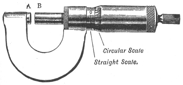
Fig. 823.—Micrometer screw gauge. It consists essentially of a screw whose thread is accurately turned to a pitch of some convenient fraction of an inch or centimetre. When the screw is screwed home, the surfaces of A and B meet, and the instrument should then read zero on both the straight and the circular scale. If this be not so, there is a zero error which must be either allowed for, or corrected by means of the screw provided for that purpose. If the former course be adopted, the reading of the instrument is taken when the faces A and B are in contact, and this number added to or subtracted from the final reading according to whether the error makes the wire apparently smaller or greater than its real size. The surfaces A and B are now screwed apart and then, after the wire to be measured (which should be clean and straight) has been introduced between them, they are screwed together to lightly grip the wire. If the gauge be screwed up too tightly the value of the measurement is destroyed, since a copper wire can easily be crushed, and in addition the accurate screw may be permanently damaged. To avoid the possibility of this happening, screw gauges are provided with a ratchet which prevents an excessive force being applied to the screw. If the pitch of the screw in the gauge be 1/20th of an inch, and the circular scale consist of 50 divisions, then for each revolution of the screw, the surface B will travel a distance equal to the pitch, that is 1/20th of an inch. The graduations on an instrument of this kind are generally 1/10th of an inch on the straight scale, with shorter lines to mark the half divisions. The thickness of a wire on the straight scale can therefore be read to the nearest 1/20th inch. Each division of the circular scale represents 1/50th of a revolution of the screw, which corresponds to a change in distance between A and B, of 1/50 of 1/20 = 1/1,000 in. If then the reading on the straight scale be 1 and on the circular scale 35, the distance between A and B is .1 + .035 = .135 inch.
Washburn and Moen's Standard Wire Gauge.—Commonly designated as W. & M. G. has been adopted by the U. S. Steel Corporation in making their wire.
New British Standard (N. B. S.).—British Imperial English Legal Standard and Standard Wire Gauge, and is variously abbreviated by S. W. G. and I. W. G.
Roebling Gauge.—Washburn Moen, American Steel & Wire Co.'s Iron Wire Gauge.
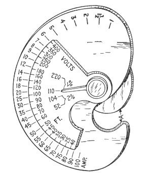
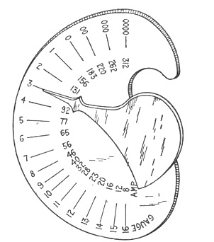
Figs. 824 and 825.—U. S. wireman's calculating gauge; views showing both sides. On the side shown in fig. 824, set the required number of feet on the small circle opposite the required number of amperes on the large circle, then set the small pointer at the required voltage and loss. Then on the other side (fig. 825) the large pointer will indicate the required size of wire in B. & S. gauge, and will also indicate the safe carrying capacity, while the wire may be gauged by slot A (fig. 824).
U. S. Standard Wire Gauge.—This gauge is used for measuring sheet and plate iron, and steel, by the U. S. Government in assessing duties, and in making requisitions for supplies.
Old English Standard Wire Gauge.—The old English gauge is the same as the Birmingham or Stubs' standard gauge, commonly designated as B. W. G. It is used chiefly for measuring sheet iron and steel, also soft steel and iron wire.
London Gauge.—Old English (not Old English Standard).
From the foregoing it is seen that great confusion exists with such a multiplicity of gauges and emphasizes the importance of specifying the gauge and of knowing what gauge to use.
In using the gauges known as Stubs' Gauges, there should be constantly borne in mind the difference between the Stubs' Iron Wire Gauge and the Stubs' Steel Wire Gauge. The Stubs' Iron Wire Gauge is the one commonly known as the English Standard Wire, or Birmingham Gauge and designates the Stubs' soft wire sizes. The Stubs' Steel Wire Gauge is the one that is used in measuring drawn steel wire or drill rods of Stubs' make and is also used by many makers of American drill rods.
STUBS' STEEL WIRE GAUGE
Letter. Size of Letter in Decimals. No. of Wire Gauge. Size of Number in Decimals. No. of Wire Gauge. Size of Number in Decimals. No. of Wire Gauge. Size of Number in Decimals.
Z .413 1 .227 28 .139 55 .050
Y .404 2 .219 29 .134 56 .045
X .397 3 .212 30 .127 57 .042
W .386 4 .207 31 .120 58 .041
V .377 5 .204 32 .115 59 .040
U .368 6 .201 33 .112 60 .039
T .358 7 .199 34 .110 61 .038
S .348 8 .197 35 .108 62 .037
R .339 9 .194 36 .106 63 .036
Q .332 10 .191 37 .103 64 .035
P .323 11 .188 38 .101 65 .033
O .316 12 .185 39 .099 66 .032
N .302 13 .182 40 .097 67 .031
M .295 14 .180 41 .095 68 .030
L .290 15 .178 42 .092 69 .029
K .281 16 .175 43 .088 70 .027
J .277 17 .172 44 .085 71 .026
I .272 18 .168 45 .081 72 .024
H .266 19 .164 46 .079 73 .023
G .261 20 .161 47 .077 74 .022
F .257 21 .157 48 .075 75 .020
E .250 22 .155 49 .072 76 .018
D .246 23 .153 50 .069 77 .016
C .242 24 .151 51 .066 78 .015
B .238 25 .148 52 .063 79 .014
A .234 26 .146 53 .058 80 .013
The following table gives the diameters, in decimal parts of an inch, of the various sizes of wire corresponding to the number of gauge numbers of the different standard wire gauges used in the United States.
TABLE OF VARIOUS WIRE GAUGES
In decimal parts of an inch
Number of Wire Gauge American, or Brown & Sharpe (B.&S.) Birmingham, or Brown & Sharpe (B. W. G.) Washburn & Moen Mfg. Co., Worcester, Mass. Trenton Iron Co., Trenton, N. J. G. W. Prentiss, Holyoke, Mass. Old English, From Brass Mfrs' List British Standard (S. W. G.)
0000000 .500
000000 .460 .464
00000 .430 .450 .432
0000 .46000 .454 .393 .400 .400
000 .40964 .425 .362 .360 .3586 .372
00 .36480 .380 .331 .330 .3282 .348
0 .32486 .340 .307 .305 .2994 .324
1 .28930 .300 .283 .285 .2777 .300
2 .25763 .284 .263 .265 .2591 .276
3 .22942 .259 .244 .245 .2401 .252
4 .20431 .238 .225 .225 .2230 .232
5 .18194 .220 .207 .205 .2047 .212
6 .16202 .203 .192 .190 .1885 .192
7 .14428 .180 .177 .175 .1758 .176
8 .12849 .165 .162 .160 .1605 .160
9 .11443 .148 .148 .145 .1471 .144
10 .10189 .134 .135 .130 .1351 .128
11 .090742 .120 .120 .1175 .1205 .116
12 .080808 .109 .105 .1050 .1065 .104
13 .071961 .095 .0920 .0925 .0928 .0920
14 .064084 .083 .0800 .0800 .0816 .08300 .0800
15 .057068 .072 .0720 .0700 .0726 .07200 .0720
16 .050820 .065 .0630 .0610 .0627 .06500 .0640
17 .045257 .058 .0540 .0525 .0546 .05800 .0560
18 .040303 .049 .0470 .0450 .0478 .04900 .0480
19 .035890 .042 .0410 .0400 .0411 .04000 .0400
20 .031961 .035 .0350 .0350 .0351 .03500 .0360
21 .028462 .032 .0320 .0310 .0321 .03150 .0320
22 .025347 .028 .0280 .0280 .0290 .02950 .0280
23 .022571 .025 .0250 .0250 .0261 .02700 .0240
24 .020100 .022 .0230 .0225 .0231 .02500 .0220
25 .017900 .020 .0200 .0200 .0212 .02300 .0200
26 .015940 .018 .0180 .0180 .0194 .02050 .0180
27 .014195 .016 .0170 .0170 .0182 .01875 .0164
28 .012641 .014 .0160 .0160 .0170 .01650 .0148
29 .011257 .013 .0150 .0150 .0163 .01550 .0136
30 .010025 .012 .0140 .0140 .0156 .01375 .0124
31 .008928 .010 .0130 .0130 .0146 .01225 .0116
32 .007950 .009 .0120 .0120 .0136 .01125 .0108
33 .007080 .008 .0110 .0110 .0130 .01025 .0100
34 .006305 .007 .0100 .0100 .0118 .00950 .0092
35 .005615 .005 .0095 .0095 .0109 .00900 .0084
36 .005000 .004 .0090 .0090 .0100 .00750 .0076
37 .004453 .0085 .0085 .0095 .00650 .0068
38 .003965 .0080 .0080 .0090 .00575 .0066
39 .003531 .0075 .0075 .0083 .00500 .0052
40 .003145 .0070 .0070 .0078 .00450 .0048
41 .0044
42 .0040
NOTE.—The sizes of wire are ordinarily expressed by an arbitrary series of numbers. Unfortunately there are several independent numbering methods, so that it is always necessary to specify the method or wire gauge used. The above table gives the numbers and diameters in decimal parts of an inch for the various wire gauges in general use.
Wiring Terms.—The various members of a complex wiring installation are designated feeders, sub-feeders, mains, branches, and taps.
A feeder is a stretch of wiring to which no connection is made except at its two ends.
A sub-feeder is of the same class as a feeder, but is distinguished either by being one of two or more connecting links between the end of a single feeder and several distributing mains, or by constituting an extension of a feeder.
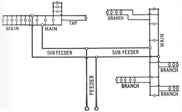
Fig. 826. Circuit diagram illustrating names of the various parts. A circuit may consist of the following parts as defined in the accompanying text: 1, feeder, 2, sub-feeders, 3, mains, 4, branches, 5, taps. It is well to clearly distinguish between these divisions because the terms are constantly used in wiring.
A main is a stretch of wiring supplied from one or more feeders or sub-feeders and distributing current to a number of taps, or else to a number of branches.
A branch distributes current among a number of lamps, etc.
A tap almost invariably delivers current to a single lamp or other device.
Reference to fig. 826 will make these definitions clearer. This diagram is intended merely to illustrate the above definitions and does not represent any special plan of wiring.


Figs. 827 and 828. Simplest forms of circuit, consisting of a main with one or more lamps at the end. The smallest size wire allowed (No. 14 B.&S. gauge) will generally be found amply large for such circuits. Note carefully the difference between a main and a branch by comparison with fig. 826. A main begins from a fuse block, while a branch is an offset from a main without any fuse block.
The simplest possible wiring installation is one in which a single lamp or compact cluster of lamps is located at the end of a main, as shown in figs. 827 and 828. In such cases calculations are almost always unnecessary, for the reason that No. 14 wire, the smallest size allowed by the underwriters, will supply several lamps at a long distance (as interior wiring goes) with a very moderate drop. For example, if the three lamps shown at the end of the main in fig. 828, be of 16 candle power each, and the voltage of the supply circuit be 110 volts, a main of No. 14 wire would supply the lamps at a distance of 135 feet from the fuse block with a drop of only 1 per cent.
When the lamps are strung along the main, however, as in fig. 826, it is sometimes necessary to choose the size of wire with regard to the drop, and in order to do this the main must be measured for either "ampere feet" or "lamp feet."
Wire Calculations.—The problem of calculating the size of wire will be presented here in as simple a form as possible, with explanation of the various steps so that any one can understand how the formula is derived.
In determining the size of wire, there are four known factors which enter into the calculation, viz.:
1. Length of circuit in feet; 2. Maximum current in amperes; 3. Drop or volts lost in the circuit, in % of the impressed voltage; 4. Heating effect of the current.
The calculation is based on the mil foot, which as previously explained, is a foot of copper wire one mil in diameter and whose resistance is equal to 10.79 ohms at 75° Fahr.
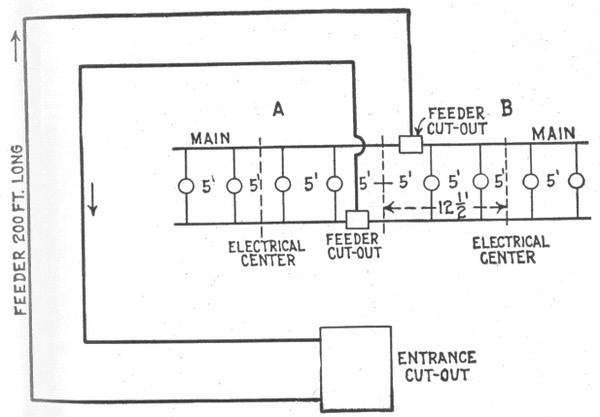
Fig. 829.—Wiring for lights requiring unusually long feeders.
The first step is to find an expression for the resistance of the wire which may be later substituted in Ohm's law formula. Accordingly, the resistance of any conductor is equal to its length in feet multiplied by its resistance per mil foot and the product divided by its area in circular mils, thus:
resistance in ohms = length in feet × resistance per mil foot circular mils
or
ohms = feet × 10.8 circular mils . . . . (1)
(calling the resistance per mil foot 10.8 instead of 10.79 to facilitate calculation).
LAMP TABLE FOR RUBBER COVERED WIRES
Showing the maximum number of 16 candle power 110 to 240 volt lamps in parallel that may be carried by the various sizes of wire without violating the underwriters' rules.
Wire size B. & S. gauge Amperes. 3.1.watt lamps. 3.5.watt lamps. 4.watt lamps.
At 110 volts. 220 V. At 110 volts. 220 V. 220 V. 230 V. 240 V.
0000 210 462 924 412 825 722 754 787
000 177 389 778 347 695 608 636 663
00 150 330 660 294 589 515 539 562
0 127 279 558 249 499 436 456 476
1 107 235 470 210 420 367 384 401
2 90 197 396 176 353 309 323 337
3 76 167 334 149 298 261 273 285
4 65 143 286 127 255 223 233 243
5 54 118 237 106 212 185 194 202
6 46 101 202 90 180 158 165 172
8 33 72 145 64 129 113 118 123
10 24 52 105 47 94 82 86 90
12 17 37 74 33 66 58 61 63
14 12 26 52 23½ 47 41 43 45
163 6 13 .. 11 .. 20 21 22
Now, according to Ohm's law,
volts = amperes × ohms . . . . (2)
hence, substituting in (2) the value for the resistance in ohms, as obtained in (1):
volts = amperes × feet × 10.8 circular mils
or using the usual symbols
E = I × feet × 10.8 circular mils . . . . (3)
or expressed in words, formula (3) means that the volts lost or drop between the beginning and end of a circuit is equal to the current flowing through the circuit multiplied by the product of the conductors' length in feet multiplied by the resistance of one mil foot of wire, divided by the area of the conductor in circular mils.
LAMP TABLE FOR WEATHER PROOF WIRES
Showing the maximum number of 16 candle power 120 to 240 volt lamps in parallel that may be carried by various sizes of weather proof wire without violating the underwriters' rules.
Wire size B. & S. gauge Amperes. 3.1.watt lamps. 3.5.watt lamps. 4.watt lamps.
110 V. 220 V. 110 V. 220 V. 220 V. 230 V. 240 V.
0000 312 686 1372 612 1225 1072 1121 1170
000 262 576 1152 514 1029 900 941 982
00 220 484 968 432 864 756 790 825
0 185 407 814 363 726 636 665 693
1 156 343 686 306 612 536 560 585
2 131 288 576 257 514 450 470 491
3 220 242 484 216 432 378 395 412
4 92 202 404 180 361 316 330 345
5 77 169 338 151 302 264 276 288
6 65 143 286 127 255 223 233 243
8 46 101 202 90 180 158 165 172
10 32 70 140 62 125 110 115 120
12 23 50 101 45 90 79 82 86
14 16 35 70 31 62 55 57 60
Now, since the length of the circuit is given as the "run" or distance one way, that is, one half the total length of wire in the circuit, formula (3) must be multiplied by 2 to get the total drop, that is:
E = I × feet × 10.8 X 2 circular mills = I × feet × 21.6 circular mills . . . . (4)
Solving the last equation for the unknown quantity, the following equation is obtained for size of wire:
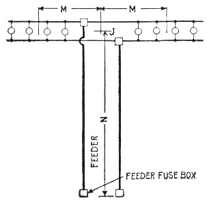
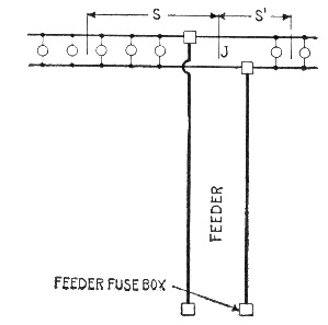
Figs. 830 and 831.—Symmetrical and unsymmetrical distribution. When a main is supplied by a feeder, the junction of the two, if practicable, is located at the electrical center of the main, as indicated in fig. 830, so that the distribution is symmetrical, that is, the ampere feet each way from the junction are the same. This is nearly always practicable in surface wiring, and when it is practiced it is only necessary to calculate the wire size for one-half of the main, as the other half is identical. In fig. 830 there are four lamps on each side of the junction, J; the center of each group is at a distance, M, so that the lamp feet in each half of the main are 5 × M. The lamp feet of the feeder would be 10 × N, N being the distance from the feeder fuse block to the junction, J. In concealed work, however, it does not always happen that a feeder can be made to join a main at its electrical center; when this is not practicable, each end of the main should be figured separately. In fig. 831, for instance, the main has five lamps on one side and two on the other, and the distances from the junction to the centers of the two groups are at unequal distances S and S'. If the distance S be 14 feet, and the lamps, 16 c. p., the lamp feet in the left hand main equals 5 × 14 = 70, while in the main to the right, taking S' at 10 feet, there are only 2 × 10 = 20 lamp feet. Hence what appears to be one continuous main in this case would have to be treated as two mains, and each part figured separately.
circular mils = I × feet × 21.6 E = amperes × feet × 21.6 "drop" . . . . (5)
The following practical example is given to illustrate the application of the formula just obtained:
EXAMPLE.—What size wire should be used on a 250 volt circuit to transmit a current of 200 amperes a distance of 350 feet to a center of distribution with a loss of three per cent. under full load?
The volts lost or drop is equal to 250 × .03 = 7.5 volts.
PROPERTIES OF COPPER WIRE
Number of gauge B. & S. Diameter in mils Area in circular mils Weight in pounds Resistance at 68° Fahr.
1,000 feet mile Feet per pound 1,000 Feet mile
0000 460 211,600 640.5 3,381 1.561 .04893 .2583
000 409.6 167,800 508 2,682 1.969 .06170 .3258
00 364.8 133,100 402.8 2,127 2.482 .07780 .4108
0 324.9 105,500 319.5 1,687 3.130 .09811 .5180
1 289.3 83,690 253.3 1,337 3.947 .12370 .6531
2 257.6 66,370 200.9 1,062 4.977 .1560 .8237
3 229.4 52,630 159.3 841.1 6.276 .1967 1.0386
4 204.3 41,740 126.4 667.4 7.914 .2480 1.3094
5 181.9 33,100 100.2 529.0 9.980 .3128 1.6516
6 162.0 26,250 79.46 419.5 12.580 .3944 2.0824
7 144.3 20,820 63.02 332.7 15.87 .4973 2.6257
8 128.5 16,510 49.98 263.9 20.01 .6271 3.3111
9 114.4 13,090 39.63 209.2 25.23 .7908 4.1754
10 101.9 10,380 31.13 166.0 31.82 .9972 5.2652
11 90.74 8,234 24.93 131.6 40.12 1.257 6.6370
12 80.81 6,530 19.77 104.4 50.59 1.586 8.374
13 71.96 5,178 15.68 82.79 63.79 2.000 10.560
14 64.08 4,107 12.43 65.63 80.44 2.521 13.311
15 57.07 3,257 9.858 52.05 101.4 3.179 16.785
16 50.82 2,583 7.818 41.28 127.9 4.009 21.168
17 45.26 2,048 6.200 32.74 161.3 5.055 26.690
18 40.30 1,624 4.917 25.96 203.4 6.374 33.655
19 35.89 1,288 3.899 20.59 256.5 8.038 42.440
20 31.96 1,022 3.092 16.33 323.4 10.14 15.340
Substituting the given value in formula (5)
circular mils = 350 × 200 × 21.6 7.5 = 201,600.
Diameter = 2 √201,600 = 449 circular mils or .449 in.
From the table (on page 731 or on page 742) the nearest (larger) size of wire is 0000 B. & S. gauge.4
WIRING TABLE FOR LIGHT AND POWER CIRCUITS
VOLTS PERCENTAGE OF LOSS
2000 1.7 1.5 1.4 1.2 1.1 1.0 0.75 0.5
1000 3.4 2.9 2.7 2.4 2.2 2.0 1.5 1.0
500 6.5 5.7 6.2 4.8 4.3 3.9 2.9 2.0
220 13.7 12.0 11.0 10.3 9.3 8.3 6.5 4.4
110 — — 20.0 18.5 17.0 15.4 12.0 8.4
52 — — — — — — 22.4 16.1
VOLTS PERCENTAGE OF LOSS (continued)
2000 0.45 0.4 0.35 0.3 0.25 0.2 0.15 0.1 0.05
1000 0.9 0.8 0.7 0.6 0.5 0.4 0.3 0.2 0.1
500 1.8 1.6 1.4 1.2 1.0 0.8 0.6 0.4 0.2
220 3.9 3.5 3.1 2.7 2.2 1.8 1.4 0.9 0.45
110 7.6 6.8 6.0 5.2 4.4 3.5 2.7 1.8 0.9
52 14.7 13.3 11.8 10.3 8.8 7.1 5.5 3.7 1.9
ACTUAL VOLTS LOST
Carrying Capacity Amperes. Size B. & S. 35 30 27.5 25 22.5 20 15 10
300 0000 345800 296400 271700 247000 222300 197600 148200 98800
245 000 274400 235200 215600 196000 176400 156800 117600 78400
215 00 217525 186450 170912 155375 139837 124300 93225 62150
190 0 172550 147900 135575 123250 110925 98600 73950 49300
160 1 136850 117300 107525 97750 87975 78200 58650 39100
135 2 108500 93000 85250 77500 69750 62000 46500 31000
115 3 86100 73800 67650 61500 55350 49200 36900 24600
100 4 68250 58500 53625 48750 43875 39000 29250 19500
90 5 54250 46500 42625 38750 34875 31000 23250 15500
80 6 43050 36900 33825 30750 27675 24600 18450 12300
60 8 26965 23130 21202 19275 17347 15420 11565 7710
40 10 16975 14550 13337 12125 10912 9700 7275 4850
30 12 10675 9150 8388 7625 6862 6100 4575 3050
22 14 6720 5760 5280 4800 4320 3840 2880 1920
55 16 4235 3630 3328 3025 2723 2420 1815 1210
ACTUAL VOLTS LOST (continued)
Carrying Capacity Amperes. Size B. & S. 9 8 7 6 5 4 3 2 1
300 0000 88920 79040 69160 59280 49400 39520 29640 19760 9880
245 000 70560 62720 54880 47040 39200 31360 23520 15680 7840
215 00 55935 49720 43505 37290 31075 24860 18645 12430 6215
190 0 44370 39440 34510 29580 24650 19720 14790 9860 4930
160 1 35190 31280 27370 23460 19550 15640 11730 7820 3910
135 2 27900 24800 21700 18600 15500 12400 9300 6200 3100
115 3 22140 19680 17220 14760 12300 9840 7380 4920 2460
100 4 17550 15600 13650 11700 9750 7800 5850 3900 1950
90 5 13950 12400 10850 9300 7750 6200 4650 3100 1550
80 6 11070 9840 8610 7380 6150 4920 3690 2460 1230
60 8 6939 6168 5397 4626 3855 3084 2313 1542 771
40 10 4365 3880 3395 2910 2425 1940 1455 970 486
30 12 2745 2440 2135 1830 1525 1220 915 610 305
22 14 1728 1536 1344 1152 960 768 576 384 192
55 16 1089 968 847 726 605 484 363 242 121
RULE.—Multiply current in amperes by single distance and refer to the nearest corresponding number under column of actual volts lost, to find size of wire. It should also be noted that the underwriters prohibit the use of wire smaller than No. 14 B. & S. gauge, except as allowed for fixture work and pendant cord.
TABLE OF WIRE EQUIVALENTS
GAUGE B. & S. NUMBER OF WIRES
2 4 8 1 6 3 2 6 4 1 2 8 2 5 6 5 1 2 1 0 2 4 2 0 4 8 4 0 9 6 8 1 9 2 1 6 3 8 4
0000 0 3 6 9 12 15 18 21 24 27 30 33 36 39
000 1 4 7 10 13 16 19 22 25 28 31 34 37 40
00 2 5 8 11 14 17 20 23 26 29 32 35 38 0+6
0 3 6 9 12 15 18 21 24 27 30 33 36 39 1+7
1 4 7 10 13 16 19 22 25 28 31 34 37 40 2+8
2 5 8 11 14 17 20 23 26 29 32 35 38 3+9 4+6
3 6 9 12 15 18 21 24 27 30 33 36 39 4+10 5+7
4 7 10 13 16 19 22 25 28 31 34 37 40 5+11 6+8
5 8 11 14 17 20 23 26 29 32 35 38 6+12 7+9
6 9 12 15 18 21 24 27 30 33 36 39 7+13 8+10
7 10 13 16 19 22 25 28 31 34 37 40 8+14 9+11
8 11 14 17 20 23 26 29 32 35 38 9+15 10+12
9 12 15 18 21 24 27 30 33 36 39 10+16 11+13
10 13 16 19 22 25 28 31 34 37 40 11+17 12+14
11 14 17 20 23 26 29 32 35 38 12+18 13+15
12 15 18 21 24 27 30 33 36 39 13+19 14+16
13 16 19 22 25 28 31 34 37 40 14+20 15+17
14 17 20 23 26 29 32 35 38 15+21 16+18
15 18 21 24 27 30 33 36 39 16+22 17+19
16 19 22 25 28 31 34 37 40 17+23 18+20
17 20 23 26 29 32 35 38 18+24 19+21
18 21 24 27 30 33 36 39 19+25 20+22
19 22 25 28 31 34 37 40 20+26 21+23
20 23 26 29 32 35 38 21+27 22+24
21 24 27 30 33 36 39 22+28 23+25
22 25 28 31 34 37 40 23+29 24+26
23 26 29 32 35 38 24+30 25+27
24 27 30 33 36 39 25+31 26+28
25 28 31 34 37 40 26+32 27+29
26 29 32 35 38 27+33 28+30
27 30 33 36 39 28+34 29+31
28 31 34 37 40 29+35 30+32
29 32 35 38 30+36 31+33
30 33 36 39 31+37 32+34
31 34 37 40 32+38 33+35
32 35 38 33+39 34+36
33 36 39 34+40 35+37
34 37 40 36+39
35 38 37+39
36 39 38+40
37 40
Ques. If the calculated size of wire be larger than any in the table how is the required area obtained?
Ans. By using two or more smaller wires in parallel, whose combined area is equal to the required area.
To facilitate finding the equivalent sizes the above table of wire equivalents has been prepared.
Ques. How is the table of wire equivalents used?
Ans. To use the table, find in the vertical column at left the size of conductor desired; then follow along horizontally until the size of wire that is desired to use for the strands, and the corresponding number at top of column will give the number of strands of that size wire required.
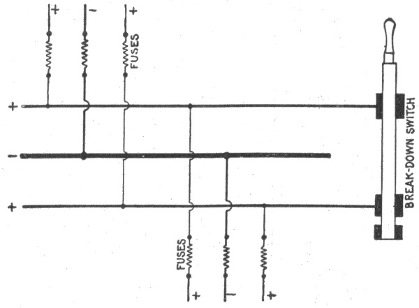
Fig. 832.—Break down switch for use on three wire circuit, enabling it to be operated break down fashion with the two outers connected together and the neutral wire serving as one side of the resultant two wire circuit. Such circuits must be figured as two wire installations of one half the three wire voltage. The size of the neutral wire of a three wire circuit depends on conditions of operation. Three wire circuits for occasional two wire working, must have a neutral wire whose cross section is equal to the combined cross sections of the two outer wires. This plan is useful for buildings supplied from a central station, as it will be satisfactory for two wire operation in emergencies, and for three wire, two phase or three phase distribution should the central station ultimately be changed over to either of those alternating current systems. The expense for the extra copper in the beginning will not be nearly so great as that entailed by a change in the wiring later on should developments require it. It is permissible, however, to make the cross section of the neutral wire smaller than that of each outer wire, if one be reasonably sure that there will never be any changes such as those just mentioned, and if the drop in the two outer wires do not exceed 1½ per cent. Under such conditions, it will be found a very good rule to calculate the neutral wire of a principal feeder for a maximum unbalancing of 25 per cent, that is, a condition under which the current in one outer wire will be 75 per cent of the current in the other one, the current in the neutral being 25 per cent of that in the heavier loaded outer wire.
Ques. What is the significance of the zig-zag line?
Ans. The figures below this line give the gauge numbers of two wires which will have the same conductivity as the corresponding conductor in left hand column.
TABLE OF CABLE CAPACITIES
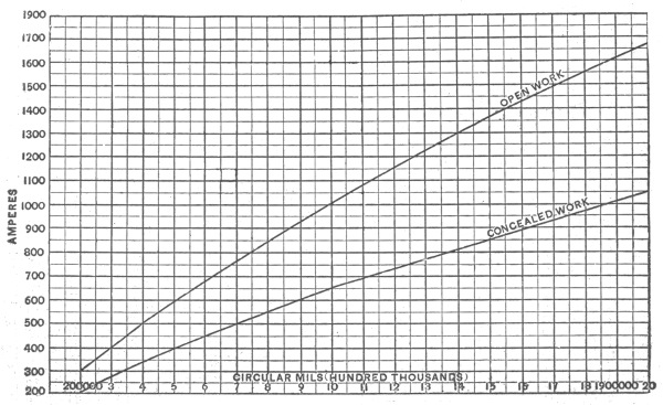
Fig. 833.—Diagram showing capacities of cables for both open and concealed work as allowed by the underwriters.
Incandescent Lamps on 660 Watt Circuits.—The standard incandescent lamp is rated as equivalent to the light given by 16 candles, and may consume, according to type and make, from 50 to 56 watts, or from 3.1 to 3.5 watts per candle power. Therefore, a 660 watt circuit will carry thirteen 16 candle power 49.6 watt lamps, or eleven 56 watt lamps.
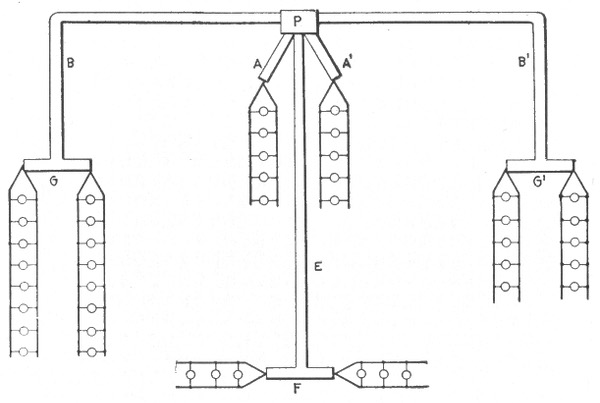
Fig. 834.—Diagram showing symmetrical and unsymmetrical distribution. The two 5 lamp centers are located at equal distances from the distributing pocket or cabinet, P, so that the sub-feeders, A and A', have equal values of lamp feet. The sub-feeders, B, B', have equal lengths, but as one supplies 10 lamps, and the other 16, the lamp feet are different, and each sub-feeder must therefore be figured separately. The main, G, should be considered as a part of the sub-feeder, B, in order to avoid the necessity for a fuse at the junction of the two. As it is symmetrically divided, only one-half of it would be considered. Thus, if the sub-feeder, B, were 50 feet long, and the main, G, 30 feet long, B would have 16 × 50 = 800 lamp feet and one-half of the main would have 8 × 15 = 120 lamp feet (assuming all 16 c. p. lamps). Hence 800 + 120 = 920 lamp feet should be taken as the load length and the proper size wire used for that figure, making the sub-feeder, B, of the same size as the main, G. The same procedure applies to the sub-feeder B' and main G'; also to the sub-feeder, E, and the main, F. The proper sizes of wire for the different circuits is easily found from the lamp feet table, after having calculated the lamp feet assigned the drop.
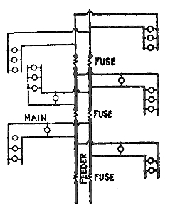
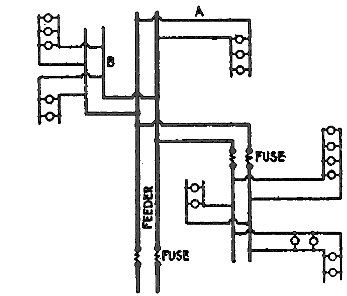
Figs. 835 and 836.—The "tree" and "modified tree" systems of wiring. The tree system consists of a feeder reducing in size and supplying mains for each floor, the general arrangement resembling the trunk and branches of a tree. Since fuses must be inserted on each floor where the size of the feeder is reduced, the system requires a large number of joints, and in the event of a fuse blowing it could not be quickly located. The tree system is not to be recommended, as it results in considerable drop, and at full load the lamps nearest the point of supply will either burn too brightly or those more remote will not give the rated candle power. In the modified tree system, fig. 836, the size of the feeder is not reduced. With this arrangement the losses are considerably reduced owing to the much smaller losses on the feeder between those centers farthest away from the point of supply.
The proper size of wire for a 660 watt circuit will depend upon the voltage for which the lamps are made. For example: a 16 candle power lamp which consumes 56 watts on 110 volt circuit will take, 56 ÷ 110 = .5 or ½ ampere of current, while the same lamp, if made for 220 volts, will take only 55 ÷ 220 = .25 or ¼ ampere. Therefore, eleven 16 candle power 56 watt lamps will require a current of 5½ amperes at 110 volts, or 2¾ amperes at 220 volts.
According to the laws of resistance, the resistance of a round wire is inversely proportional to the square of the diameter, and if the circuit be taken at 100 feet, and the allowable percentage of drop at 1 volt, then according to formula, (5) on page 748, the wire required for a circuit carrying eleven 16 candle power 56 watt 110 volt lamps, will have a cross sectional area of,
5.5 × 100 × 21.6 1 = 11,880 circular mils.
while the same number of lamps on a 220 volt circuit will require wire having a cross sectional area of,
2.75 × 100 × 21.6 1 = 5,940 circular mils.
In order to conform to the underwriters' requirements, No. 8. B. & S. gauge, wire must be used for the circuit carrying the 110 volt lamps, while No. 12, B. & S. wire, would be sufficient for the 220 volt circuit.
In the case shown in fig. 829, the branch circuits A and B are identical, each supplying four 16 candle power lamps requiring 3.5 watts per candle power at 110 volts or carrying a load of 4 × 16 × 3.5 = 224 watts, = 224 ÷ 110 = 2 amperes.
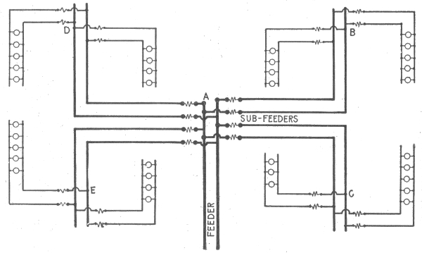
Fig. 837.—Distribution with sub-feeders (multi-center distribution). The feeder connects at a central point, A, with several sub-feeders which run to distributing centers, as at B, C, D, and E. With this arrangement, compound wound dynamos may be so designed that the pressure at A will remain nearly uniform for all loads. If, for instance, the wiring be proportioned for 2% drop, the dynamos may be over compounded to that extent, and the even illumination will compensate for the extra cost in the installation.
The distance from the feeder junction or cut out to the electrical center of each branch circuit is 12.5 feet. The compact area of distribution permits the reduction of the loss of volts to 1 per cent, or 110 × .01 = 1.1 volts "drop." Then substituting in formula (5) on page 748 the values for amperes, feet and drop as obtained above
2 × 25 × 21.6 1.1 = 981 circular mils,
or a value far below that of even No. 18 wire, B. & S. gauge (see table on page 731), but the smallest wire allowed by the underwriters for the mains A and B is No. 14, B. & S. gauge.
In calculating the size of wire for the feeders the total load must be considered. This is equal to eight 16 candle power lamps, requiring 3.5 watts per candle power at 110 volts = 8×16×3.5 = 448 watts = 4 amperes.
The distance from the entrance cut out to the feeder cut out is 200 feet. The drop should not be greater than 1.5 per cent. or 110×1.5 = 1.6 volts. Then,
4×200×21.6 1.6 = 10,800 circular mils
a value which indicates that No. 8 wire, B. & S. gauge, must be used for the feeders in order to keep the drop within the limit of predetermined value.
TABLE FOR TAPS, BRIDGES OR OTHER WIRES AT NEGLIGIBLE DROP
Wire Nos. 0 1 2 3 4 5 6 7 8 9 10 12 14 16 18
Lamp 52 v. 300 260 200 160 130 100 80 65 50 38 24 15 9 6
Feet 110v. 1,280 1,085 860 680 560 435 345 280 220 160 100 60 40 25
NOTE.—In using this table, it is only necessary to calculate the lamp feet of the tap and take the size of wire corresponding to the nearest greater number of lamp feet in the table. The lamp feet specified by this table should not be exceeded by more than 10 per cent. Thus, if a tap measure 108 lamp feet, in 110 volt lamps, No. 12 wire would be used. But if it measure 115 lamp feet, it would be advisable to use No, 10 wire.
Constant Voltage Arc Lamp Circuits.—The branch conductor should have a carrying capacity about fifty per cent. greater than the normal current required by the lamp, so as to provide for the heavy current required when the lamp is started. The underwriters prohibit the use of any size wire under No. 12 for parallel connected arc light circuits.
Constant Current Series Arc Lamp Circuits.—The wiring for series connected arc lamps should never be concealed nor encased unless requested by the electrical inspector.
For all interior wiring of this class, approved rubber covered wire should be used, and the wire should always be rigidly supported on porcelain or glass insulators which will hold the wires at a distance of at least one inch from the surface wired over. The wires on all circuits up to 750 volts, should be kept at least 4 inches from each other, and 8 inches apart on circuits of over 750 volts. No wires carrying a current having a pressure exceeding 3,500 volts should be carried into or over any building except central stations and sub-stations.
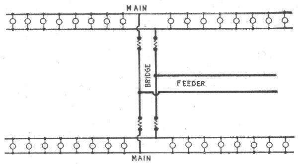
Fig. 838.—Diagram showing "bridge wiring." This method is used in the case of two parallel mains where one feeder is ample for both. The feeder is run to a central point as shown and connected to the two mains by a so called "bridge." The arrangement clearly gives good distribution and effects a saving in copper and labor, for if the bridge were omitted, two feeders would be necessary.
Wire Calculations for Motors.—The proper size of wire for a motor may be readily determined by means of the following formula:
circular mils = H.P. × 746 × D × 21.6 E × L × K . . . . (6)
in which
H.P. = horse power of motor; 746 = watts per H.P.; D = length of motor circuit from fuse block to motor;
21.6 = ohms per foot run in circuit where wires are one mil in diameter; E = voltage at the motor; L = drop in percentage of the voltage at the motor; K = efficiency of the motor expressed as a decimal.
The average values for K are about as follows: 1 H.P., .75; 3 H.P., .80; 5 H.P., .80; 10 H.P. and over, 90 per cent.
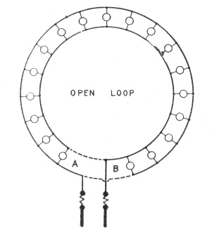
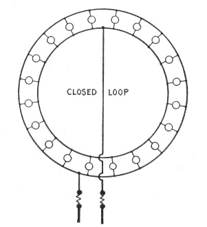
Figs. 839 and 840.—Wrong and right methods of loop wiring. In general, when a large percentage of loss is allowed with lamps at short distances, the size of wire, calculated simply in accordance with the resistance rules, will be found too small to carry the current safely. This fact is often overlooked, and even though wires may have been correctly calculated for a uniform percentage of loss, they will become painfully hot simply because the table of carrying capacity was not consulted. The cross connection of mains wherever possible, for the purpose of equalizing the pressure, will also often reduce the heating effects of the current. An example of this is shown in the above figures. A circle of lights was wired as in fig. 839, and after the current had been turned on, the wires of the circle became hot, and there was quite a perceptible difference of candle power between the lights near A and those near B. Investigation disclosed the fact that the loop, contrary to instructions, had been left open. A few inches of wire as shown in dotted lines remedied the fault. A better arrangement, however, is shown in fig. 840.
EXAMPLE.—What is the proper size of wire for a 10 H.P. motor, run at 220 volts, allowable drop 2 per cent. on 200 foot circuit.
Substituting the given values in the formula on page 758:
Circular mils = 10 × 746 × 200 × 21.6 220 × 4.4 × .9 = 36,991.
The nearest larger value to this result, in the table of carrying capacities of copper wire (page 731), is 41,740, corresponding to No. 4 wire, B. & S. gauge.
In all cases the size of the wire thus formed should be compared with that allowed by the underwriters for full load current of motor, plus 25 per cent. of that current, and if the size calculated happen to be smaller than the allowable size, it should be increased to the latter, otherwise it will not pass inspection.
TABLE OF AMPERES PER MOTOR
H. P. Per Cent. Eff. Watts Input 50 Volts 100 Volts 220 Volts 500 Volts
¾ 70 800 16 7 4 2
1½ 70 1600 32 15 7 3
3 75 2980 60 27 14 6
5 80 4660 93 42 21 9
7½ 85 6580 132 60 30 13
10 85 8780 176 80 40 18
15 85 13200 264 120 60 26
20 85 17600 352 160 80 35
25 85 21900 438 199 100 44
30 90 24900 498 226 113 50
40 90 33200 664 301 151 66
50 90 41400 828 376 188 83
60 90 49700 994 452 226 99
70 90 58000 1160 527 264 116
80 90 66300 1330 608 302 133
90 90 74600 1490 678 339 149
100 90 82900 1660 755 377 166
120 90 99500 1990 905 453 199
150 90 124000 2480 1130 564 248
TABLE OF AMPERES PER DYNAMO
Appx. Appx.
K.W. 125 Vs. 250 Vs. 500 Vs. H.P. K.W. 125 Vs. 250 Vs. 500 Vs. H.P.
1. 8 4 2 1.3 30. 240 120 60 40.
2. 16 8 4 2.7 37.5 300 150 75 50.
3. 24 12 6 4.0 40. 320 160 80 53.
5. 40 20 10 6.7 50. 400 200 100 67.
7.5 60 30 15 10. 60. 480 240 120 80.
10. 80 40 20 13. 75. 600 300 150 100.
12.5 100 50 25 17. 100. 800 400 200 134.
15. 120 60 30 20. 125. 1000 500 250 167.
20. 160 80 40 27. 150. 1200 600 300 201.
25. 200 100 50 34. 200. 1600 800 400 268.
To determine the current required for a motor, as for instance, the 10 H. P. motor under consideration, multiply the horsepower by 746, and divide the product by the voltage of the motor multiplied by its efficiency as follows: (10 × 746) ÷ (220 × .90) = 37.6 amperes.
This value increased by 25 per cent. of itself (37.6 × .25 = 9.4 amp.) is equal to 37.6 plus 9.4 = 47 amperes. In the table of carrying capacities of copper wire (page 731), 46 amperes is given as the allowable carrying capacity of No. 6, B. & S. gauge, rubber covered wire; therefore No. 5 wire must be used.
Calculations for Three Wire Circuit.—In all cases of interior conduit work, and in most cases of inside open work, the main feeders from a three wire source of supply are installed on the three wire plan, and the sub-feeders and distributing mains, on the two wire plan, except where the application of the method necessitates the use of unwieldy sizes.
In laying out sub-feeders and mains, the total load, under normal operating conditions, should be divided as nearly as possible into two equal parts, and one part connected on each side of the neutral part of the entrance cut out, or the neutral bus bar of the switch board or panel board in an isolated plant, thus making the load on each side of the neutral wire of the feeder as near equal as possible.
Fig. 841 shows a three wire panel board with connection for 12 mains; those shown in solid lines as A, B, C, etc., being connected between the neutral wire and the negative wire of the feeder, and those shown by dotted lines as G, H, I, etc., being connected between the neutral wire and the positive wire of the feeder. The total load consists of ninety-one 16 candle power lamps, which are so distributed that the positive wire of the feeder carries the current for 46 lamps, and the negative wire, 45 lamps, the neutral wire carrying the difference or current for 1 lamp.
The proper size of wire for the mains may be calculated as already explained, but in calculating the outer wires of the three wire feeder, the neutral wire should be disregarded and the outer wires connected as a two wire circuit carrying the total load of 91 lamps at the over all pressure of 220 volts.
EXAMPLE.—Ninety-one 16 candle power lamps consuming 3.1 watts per candle power at a pressure of 110 volts, will require a current of
16 × 3.1 × 91 110 = 41 amperes.
The distance from the entrance cut out to the main or feeder switch is 200 feet, then for a 2 per cent. drop, or a loss of 110×.02=2.2 volts, the cross sectional area of the wire will be,
41 amperes × 200 feet × 21.6 2.2 volts = 80,509 circular mils.
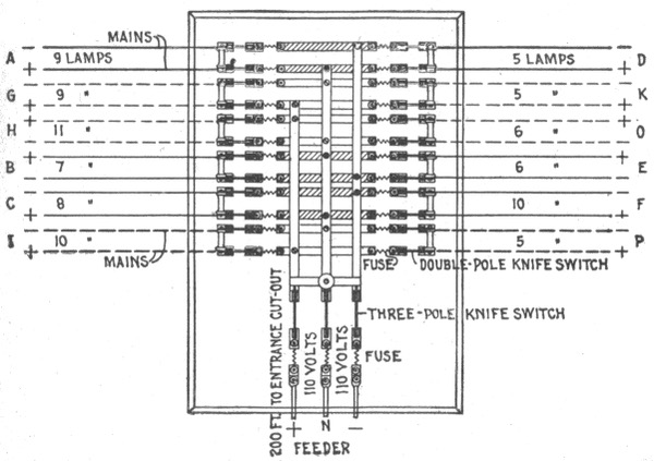
Fig. 841.—Three wire circuit panel board with connections for 12 mains. The wires shown in solid lines as A, B, C, etc., are connected between the neutral wire and the negative wire of the feeder, and those shown by dotted lines, as G, H, I, etc., are connected between the neutral wire and the positive wire of the feeder.
The joint resistance of the lamps on a three wire system, however, would be four times greater than on a two wire system; consequently the resistance of the outer wires of the feeder in this case will be four times greater for the same percentage of loss, and the cross sectional area of each of the outer wires will be, 80,509÷4=20,127 circular mils. According to the underwriters' rules, this value compels the use of No. 6 B. & S. gauge wire.
If the lamp voltage, 110 volts, be used, the two wire formula (5) given on page 748 must be modified to,
circular mils = amperes × feet × 21.6 drop × 4
but if an over all voltage, (that is, the voltage between the outer wires), of 220 volts be used, the two wire formula does not require any modification.
The proper size of wire may also be calculated by means of the formula
drop 2 × distance × amperes = resistance per foot . . . . (1)
Example.—If in calculating a three wire feeder, the over all voltage be 220 volts, the drop = 4.4 volts, twice the distance = 400 feet, and the current = 20.5 amperes, then,
4.4 volts 400 feet × 20.5 amperes = .0005365 ohms per foot.
In the table of the properties of copper wire which gives the resistance of various sizes of wire, it will be noted that at all of the given temperatures No. 8 wire has a resistance greater than the value just calculated, therefore, No. 6 B. & S. gauge wire should be used for the outer wires of the feeder. In the table the resistance is given per 1,000 feet, hence it is only necessary to move the decimal point to obtain the resistance per foot.
If the calculation be based on the lamp voltage, 110 volts, the formula (1) must be modified to
drop × 4 2 × distance × amperes = resistance . . . . (2)
In this case, drop = 2.2 volts, 2 × distance = 400 feet, and current = 41 amperes, then,
2.2 volts × 4 400 feet × 41 amp. = 8.8 16,400 = .005364 ohms.
Size of the Neutral Wire.—In three wire circuits, the size of the neutral wire will depend to a great extent upon operating conditions. In the case of installations which occasionally have to be worked as two wire systems, the cross section of the neutral wire should be equal to the combined cross section of the two outer wires.
For interior wiring which must pass inspection, the neutral wire must always be twice the size of one of the outside wires. However, for general distribution, if it be reasonably sure that the system will always be worked three wire and that the drop in the two outer wires does not exceed 1½ per cent., the cross section of the neutral wire may be made smaller than that of one of the outer wires. In such a case the size of the neutral wire may be calculated for a maximum unbalancing of 25 per cent., when the current in one of the outer wires is 75 per cent. of the current in the other outer wire.
For instance, suppose that in a balanced system, the total load on each of the outer wires of a feeder be 211 amperes, and that on account of certain operating conditions, this load has to be divided unequally so as to put 242 amperes on one of the outer wires, and 181 amperes on the other outer wire. In this case the neutral wire will carry 60 amperes, or 25 per cent. of the current carried by the heavier outer wire.
If the drop in the outer wires exceed 1½ per cent., the cross section of the neutral wire will have to be equal to or larger than that of each of the outer wires, otherwise the drop in the neutral wire will exceed ½ volt with an unbalancing of 25 per cent.