VOLUME XIV SLICE VII Ireland to Isabey, Jean Baptiste (continued 8)
Reading edition
95. The car casting system deserves description chiefly because it shows how, when the scale of operations is as enormous as it is in the Bessemer process, even a slight simplification and a slight heat-saving may be of great economic importance.
Whatever be the form into which the steel is to be rolled, it must in general first be poured from the Bessemer converter in which it is made into a large clay-lined ladle, and thence cast in vertical pyramidal ingots. To bring them to a temperature suitable for rolling, these ingots must be set in heating or soaking furnaces (§ 125), and this should be done as soon as possible after they are cast, both to lessen the loss of their initial heat, and to make way for the next succeeding lot of ingots, a matter of great importance, because the charges of steel follow each other at such very brief intervals. A pair of working converters has made 4958 charges of 10 tons each, or a total of 50,547 tons, in one month, or at an average rate of a charge every seven minutes and twenty-four seconds throughout every working day. It is this extraordinary rapidity that makes the process so economical and determines the way in which its details must be carried out. Moreover, since the mould acts as a covering to retard the loss of heat, it should not be removed from the ingot until just before the latter is to be placed in its soaking furnace. These conditions are fulfilled by the car casting system of F. W. Wood, of Sparrows Point, Md., in which the moulds, while receiving the steel, stand on a train of cars, which are immediately run to the side of the soaking furnace. Here, as soon as the ingots have so far solidified that they can be lifted without breaking, their moulds are removed and set on an adjoining train of cars, and the ingots are charged directly into the soaking furnace. The mould-train now carries its empty moulds to a cooling yard, and, as soon as they are cool enough to be used again, carries them back to the neighbourhood of the converters to receive a new lot of steel. In this system there is for each ingot and each mould only one handling in which it is moved as a separate unit, the mould from one train to the other, the ingot from its train into the furnace. In the other movements, all the moulds and ingots of a given charge of steel are grouped as a train, which is moved as a unit by a locomotive. The difficulty in the way of this system was that, in pouring the steel from ladle to mould, more or less of it occasionally spatters, and these spatterings, if they strike the rails or the running gear of the cars, obstruct and foul them, preventing the movement of the train, because the solidified steel is extremely tenacious. But this cannot be tolerated, because the economy of the process requires extreme promptness in each of its steps. On account of this difficulty the moulds formerly stood, not on cars, but directly on the floor of a casting pit while receiving the molten steel. When the ingots had so far solidified that they could be handled, the moulds were removed and set on the floor to cool, the ingots were set on a car and carried to the soaking furnace, and the moulds were then replaced in the casting pit. Here each mould and each ingot was handled as a separate unit twice, instead of only once as in the car casting system; the ingots radiated away great quantities of heat in passing naked from the converting mill to the soaking furnaces, and the heat which they and the moulds radiated while in the converting mill was not only wasted, but made this mill, open-doored as it was, so intolerably hot, that the cost of labour there was materially increased. Mr Wood met this difficulty by the simple device of so shaping the cars that they completely protect both their own running gear and the track from all possible spattering, a device which, simple as it is, has materially lessened the cost of the steel and greatly increased the production. How great the increase has been, from this and many other causes, is shown in Table III.
Table III.—Maximum Production of Ingots by a Pair of American Converters.
Gross Tons per Week.
1870 254
1880 3,433
1889 8,549
1899 (average for a month) 11,233
1903 15,704
Thus in thirty-three years the rate of production per pair of vessels increased more than sixty-fold. The production of European Bessemer works is very much less than that of American. Indeed, the whole German production of acid Bessemer steel in 1899 was at a rate but slightly greater than that here given for one pair of American converters; and three pairs, if this rate were continued, would make almost exactly as much steel as all the sixty-five active British Bessemer converters, acid and basic together, made in 1899.
96. Range in Size of Converters.—In the Bessemer process, and indeed in most high-temperature processes, to operate on a large scale has, in addition to the usual economies which it offers in other industries, a special one, arising from the fact that from a large hot furnace or hot mass in general a very much smaller proportion of its heat dissipates through radiation and like causes than from a smaller body, just as a thin red-hot wire cools in the air much faster than a thick bar equally hot. Hence the progressive increase which has occurred in the size of converters, until now some of them can treat a 20-ton charge, is not surprising. But, on the other hand, when only a relatively small quantity of a special kind of steel is needed, very much smaller charges, in some cases weighing even less than half a ton, have been treated with technical success.
97. The Bessemer Process for making Steel Castings.—This has been particularly true in the manufacture of steel castings, i.e. objects usually of more or less intricate shape, which are cast initially in the form in which they are to be used, instead of being forged or rolled to that form from steel cast originally in ingots. For making castings, especially those which are so thin and intricate that, in order that the molten steel may remain molten long enough to run into the thin parts of the mould, it must be heated initially very far above its melting-point, the Bessemer process has a very great advantage in that it can develop a much higher temperature than is attainable in either of its competitors, the crucible and the open-hearth processes. Indeed, no limit has yet been found to the temperature which can be reached, if matters are so arranged that not only the carbon and silicon of the pig iron, but also a considerable part of the metallic iron which is the iron itself, are oxidized by the blast; or if, as in the Walrand-Legenisel modification, after the combustion of the initial carbon and silicon of the pig iron has already raised the charge to a very high temperature, a still further rise of temperature is brought about by adding more silicon in the form of ferro-silicon, and oxidizing it by further blowing. But in the crucible and the open-hearth processes the temperature attainable is limited by the danger of melting the furnace itself, both because some essential parts of it, which, unfortunately, are of a destructible shape, are placed most unfavourably in that they are surrounded by the heat on all sides, and because the furnace is necessarily hotter than the steel made within it. But no part of the Bessemer converter is of a shape easily affected by the heat, no part of it is exposed to the heat on more than one side, and the converter itself is necessarily cooler than the metal within it, because the heat is generated within the metal itself by the combustion of its silicon and other calorific elements. In it the steel heats the converter, whereas in the open-hearth and crucible processes the furnace heats the steel.
98. The open-hearth process consists in making molten steel out of pig or cast iron and “scrap,” i.e. waste pieces of steel and iron melted together on the “open hearth,” i.e. the uncovered basin-like bottom of a reverberatory furnace, under conditions of which fig. 18 may give a general idea. The conversion of cast iron into steel, of course, consists in lessening its content of the several foreign elements, carbon, silicon, phosphorus, &c. The open-hearth process does this by two distinct steps: (1) by oxidizing and removing these elements by means of the flame of the furnace, usually aided by the oxygen of light charges of iron ore, and (2) by diluting them with scrap steel or its equivalent. The “pig and ore” or “Siemens” variety of the process works chiefly by oxidation, the “pig and scrap” or “Siemens-Martin” variety chiefly by dilution, sometimes indeed by extreme dilution, as when 10 parts of cast iron are diluted with 90 parts of scrap. Both varieties may be carried out in the basic and dephosphorizing way, i.e. in presence of a basic slag and in a basic- or neutral-lined furnace; or in the acid and undephosphorizing way, in presence of an acid, i.e. silicious slag, and in a furnace with a silicious lining.
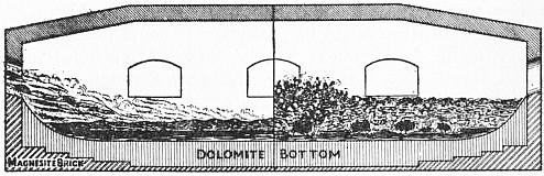
Fig. 18.—Open-Hearth Process.
Half Section showing condition of charge when boiling very gently. Half Section showing condition of charge when boiling violently during oreing.
The charge may be melted down on the “open hearth” itself, or, as in the more advanced practice, the pig iron may be brought in the molten state from the blast furnace in which it is made. Then the furnaceman, controlling the decarburization and purification of the molten charge by his examination of test ingots taken from time to time, gradually oxidizes and so removes the foreign elements, and thus brings the metal simultaneously to approximately the composition needed and to a temperature far enough above its present melting-point to permit of its being cast into ingots or other castings. He then pours or taps the molten charge from the furnace into a large clay-lined casting ladle, giving it the final additions of manganese, usually with carbon and often with silicon, needed to give it exactly the desired composition. He then casts it into its final form through a nozzle in the bottom of the casting ladle, as in the Bessemer process.
The oxidation of the foreign elements must be very slow, lest the effervescence due to the escape of carbonic oxide from the carbon of the metal throw the charge out of the doors and ports of the furnace, which itself must be shallow in order to hold the flame down close to the charge. It is in large part because of this shallowness, which contrasts so strongly with the height and roominess of the Bessemer converter, that the process lasts hours where the Bessemer process lasts minutes, though there is the further difference that in the open-hearth process the transfer of heat from flame to charge through the intervening layer of slag is necessarily slow, whereas in the Bessemer process the heat, generated as it is in and by the metallic bath itself, raises the temperature very rapidly. The slowness of this rise of the temperature compels us to make the removal of the carbon slow for a very simple reason. That removal progressively raises the melting-point of the metal, after line Aa of Fig. 1, i.e. makes the charge more and more infusible; and this progressive rise of the melting-point of the charge must not be allowed to outrun the actual rise of temperature, or in other words the charge must always be kept molten, because once solidified it is very hard to remelt. Thus the necessary slowness of the heating up of the molten charge would compel us to make the removal of the carbon slow, even if this slowness were not already forced on us by the danger of having the charge froth so much as to run out of the furnace.
The general plan of the open-hearth process was certainly conceived by Josiah Marshall Heath in 1845, if not indeed by Réaumur in 1722, but for lack of a furnace in which a high enough temperature could be generated it could not be carried out until the development of the Siemens regenerative gas furnace about 1860. It was in large part through the efforts of Le Chatelier that this process, so long conceived, was at last, in 1864, put into actual use by the brothers Martin, of Sireuil in France.
99. Siemens Open-Hearth Furnace.—These furnaces are usually stationary, but in that shown in figs. 19 to 22 the working chamber or furnace body, G of fig. 22, rotates about its own axis, rolling on the rollers M shown in fig. 21. In this working chamber, a long quasi-cylindrical vessel of brickwork, heated by burning within it pre-heated gas with pre-heated air, the charge is melted and brought to the desired composition and temperature. The working chamber indeed is the furnace proper, in which the whole of the open-hearth process is carried out, and the function of all the rest of the apparatus, apart from the tilting mechanism, is simply to pre-heat the air and gas, and to lead them to the furnace proper and thence to the chimney. How this is done may be understood more easily if figs. 19 and 20 are regarded for a moment as forming a single diagrammatic figure instead of sections in different planes. The unbroken arrows show the direction of the incoming gas and air, the broken ones the direction of the escaping products of their combustion. The air and gas, the latter coming from the gas producers or other source, arrive through H and J respectively, and their path thence is determined by the position of the reversing valves K and K′. In the position shown in solid lines, these valves deflect the air and gas into the left-hand pair of “regenerators” or spacious heat-transferring chambers. In these, bricks in great numbers are piled loosely, in such a way that, while they leave ample passage for the gas and air, yet they offer to them a very great extent of surface, and therefore readily transfer to them the heat which they have as readily sucked out of the escaping products of combustion in the last preceding phase. The gas and air thus separately pre-heated to about 1100° C. (2012° F.) rise thence as two separate streams through the uptakes (fig. 22), and first mix at the moment of entering the working chamber through the ports L and L′ (fig. 19). As they are so hot at starting, their combustion of course yields a very much higher temperature than if they had been cold before burning, and they form an enormous flame, which fills the great working chamber. The products of combustion are sucked by the pull of the chimney through the farther or right-hand end of this chamber, out through the exit ports, as shown by the dotted arrows, down through the right-hand pair of regenerators, heating to perhaps 1300° C. the upper part of the loosely-piled masses of brickwork within them, and thence past the valves K and K′ to the chimney-flue O. During this phase the incoming gas and air have been withdrawing heat from the left-hand regenerators, which have thus been cooling down, while the escaping products of combustion have been depositing heat in the right-hand pair of regenerators, which have thus been heating up. After some thirty minutes this condition of things is reversed by turning the valves K and K′ 90° into the positions shown in dotted lines, when they deflect the incoming gas and air into the right-hand regenerators, so that they may absorb in passing the heat which has just been stored there; thence they pass up through the right-hand uptakes and ports into the working chamber, where as before they mix, burn and heat the charge. Thence they are sucked out by the chimney-draught through the left-hand ports, down through the uptakes and regenerators, here again meeting and heating the loose mass of “regenerator” brickwork, and finally escape by the chimney-flue O. After another thirty minutes the current is again reversed to its initial direction, and so on. These regenerators are the essence of the Siemens or “regenerative furnace”; they are heat-traps, catching and storing by their enormous surface of brickwork the heat of the escaping products of combustion, and in the following phase restoring the heat to the entering air and gas. At any given moment one pair of regenerators is storing heat, while the other is restoring it.
Fig. 19.—Section on EF through Furnace and Port Ends.
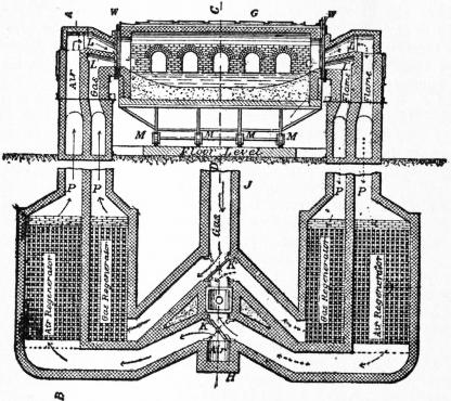
Fig. 20.—Plan through Regenerators, Flues and Reversing Valves.
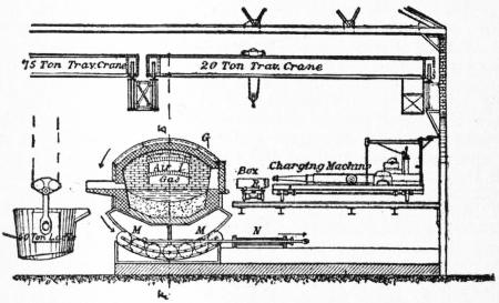
Fig. 21.—Section on CD through Body of Furnace.
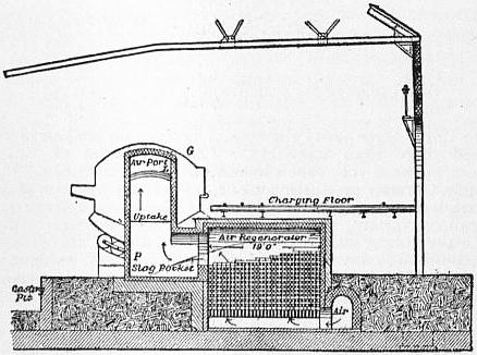
Fig. 22.—Section on AB through Uptake, Slag Pocket and Regenerator.
Figs. 19 to 22.—Diagrammatic Sections of Tilting Siemens Furnace.
G, Furnace body. H, Air supply. J, Gas supply. K, Air reversing valve. K′, Gas reversing valve. L, Air port. L′, Gas port. M, Rollers on which the furnace tilts. N, Hydraulic cylinder for tilting the furnace. O, Flue leading to chimney. P, Slag pockets. R, Charging boxes. W, Water-cooled joints between furnace proper, G, and ports L, L′.
The tilting working chamber is connected with the stationary ports L and L′ by means of the loose water-cooled joint W in Campbell’s system, which is here shown. The furnace, resting on the rollers M, is tilted by the hydraulic cylinder N. The slag-pockets P (fig. 22), below the uptakes, are provided to catch the dust carried out of the furnace proper by the escaping products of combustion, lest it enter and choke the regenerators. Wellman’s tilting furnace rolls on a fixed rack instead of on rollers. By his charging system a charge of as much as fifty tons is quickly introduced. The metal is packed by unskilled labourers in iron boxes, R (fig. 21), standing on cars in the stock-yard. A locomotive carries a train of these cars to the track running beside a long line of open-hearth furnaces. Here the charging machine lifts one box at a time from its car, pushes it through the momentarily opened furnace door, and empties the metal upon the hearth of the furnace by inverting the box, which it then replaces on its car.
100. The proportion of pig to scrap used depends chiefly on the relative cost of these two materials, but sometimes in part also on the carbon content which the resultant steel is to have. Thus part at least of the carbon which a high-carbon steel is to contain may be supplied by the pig iron from which it is made. The length of the process increases with the proportion of pig used. Thus in the Westphalian pig and scrap practice, scrap usually forms 75 or even 80% of the charge, and pig only from 20 to 25%, indeed only enough to supply the carbon inevitably burnt out in melting the charge and heating it up to a proper casting temperature; and here the charge lasts only about 6 hours. In some British and Swedish “pig and ore” practice (§ 98), on the other hand, little or no scrap is used, and here the removal of the large quantity of carbon, silicon and phosphorus prolongs the process to 17 hours. The common practice in the United States is to use about equal parts of pig and scrap, and here the usual length of a charge is about ll½ hours. The pig and ore process is held back, first by the large quantity of carbon, and usually of silicon and phosphorus, to be removed, and second by the necessary slowness of their removal. The gangue of the ore increases the quantity of slag, which separates the metal from the source of its heat, the flame, and thus delays the rise of temperature; and the purification by “oreing,” i.e. by means of the oxygen of the large lumps of cold iron ore thrown in by hand, is extremely slow, because the ore must be fed in very slowly lest it chill the metal both directly and because the reaction by which it removes the carbon of the metal, Fe2O3 + C = 2FeO + CO, itself absorbs heat. Indeed, this local cooling aggravates the frothing. A cold lump of ore chills the slag immediately around it, just where its oxygen, reacting on the carbon of the metal, generates carbonic oxide; the slag becomes cool, viscous, and hence easily made to froth, just where the froth-causing gas is evolved.
The length of these varieties of the process just given refers to the basic procedure. The acid process goes on much faster, because in it the heat insulating layer of slag is much thinner. For instance it lasts only about 8½ hours when equal parts of pig and scrap are used, instead of the 11½ hours of the basic process. Thus the actual cost of conversion by the acid process is materially less than by the basic, but this difference is more than outweighed in most places by the greater cost of pig and scrap free enough from phosphorus to be used in the undephosphorizing acid process.
101. Three special varieties of the open-hearth process, the Bertrand-Thiel, the Talbot and the Monell, deserve notice. Bertrand and Thiel oxidize the carbon of molten cast iron by pouring it into a bath of molten iron which has first been oxygenated, i.e. charged with oxygen, and superheated, in an open-hearth furnace. The two metallic masses coalesce, and the reaction between the oxygen of one and the carbon of the other is therefore extremely rapid because it occurs throughout their depth, whereas in common procedure oxidation occurs only at the upper surface of the bath of cast iron at its contact with the overlying slag. Moreover, since local cooling, with its consequent viscosity and tendency to froth, are avoided, the frothing is not excessive in spite of the rapidity of the reaction. The oxygenated metal is prepared by melting cast iron diluted with as much scrap steel as is available, and oxidizing it with the flame and with iron ore as it lies in a thin molten layer on the hearth of a large open-hearth furnace; the thinness of the layer hastens the oxidation, and the large size of the furnace permits considerable frothing. But the oxygenated metal might be prepared easily in a Bessemer converter.
To enlarge the scale of operations makes strongly for economy in the open-hearth process as in other high temperature ones. Yet the use of an open-hearth furnace of very great capacity, say of 200 tons per charge, has the disadvantage that such very large lots of steel, delivered at relatively long intervals, are less readily managed in the subsequent operations of soaking and rolling down to the final shape, than smaller lots delivered at shorter intervals. To meet this difficulty Mr B. Talbot carries on the process as a quasi-continuous instead of an intermittent one, operating on 100-ton or 200-ton lots of cast iron in such a way as to draw off his steel in 20-ton lots at relatively short intervals, charging a fresh 20-ton lot of cast iron to replace each lot of steel thus drawn off, and thus keeping the furnace full of metal from Monday morning till Saturday night. Besides minor advantages, this plan has the merit of avoiding an ineffective period which occurs in common open-hearth procedure just after the charge of cast iron has been melted down. At this time the slag is temporarily rich in iron oxide and silica, resulting from the oxidation of the iron and of its silicon as the charge slowly melts and trickles down. Such a slag not only corrodes the furnace lining, but also impedes dephosphorization, because it is irretentive of phosphorus. Further, the relatively low temperature impedes decarburization. Clearly, no such period can exist in the continuous process.
At a relatively low temperature, say 1300° C., the phosphorus of cast iron oxidizes and is removed much faster than its carbon, while at a higher temperature, say 1500° C., carbon oxidizes in preference to phosphorus. It is well to remove this latter element early, so that when the carbon shall have fallen to the proportion which the steel is to contain, the steel shall already be free from phosphorus, and so ready to cast. In common open-hearth procedure, although the temperature is low early in the process, viz. at the end of the melting down, dephosphorization is then impeded by the temporary acidity of the slag, as just explained. At the Carnegie works Mr Monell gets the two dephosphorizing conditions, low temperature and basicity of slag, early in the process, by pouring his molten but relatively cool cast iron upon a layer of pre-heated lime and iron oxide on the bottom of the open-hearth furnace. The lime and iron oxide melt, and, in passing up through the overlying metal, the iron oxide very rapidly oxidizes its phosphorus and thus drags it into the slag as phosphoric acid. The ebullition from the formation of carbonic oxide puffs up the resultant phosphoric slag enough to make most of it run out of the furnace, thus both removing the phosphorus permanently from danger of being later deoxidized and returned to the steel, and partly freeing the bath of metal from the heat-insulating blanket of slag. Yet frothing is not excessive, because the slag is not, as in common practice, locally chilled and made viscous by cold lumps of ore.
102. In the duplex process the conversion of the cast iron into steel is begun in the Bessemer converter and finished in the open-hearth furnace. In the most promising form of this process an acid converter and a basic open-hearth furnace are used. In the former the silicon and part of the carbon are moved rapidly, in the latter the rest of the carbon and the phosphorus are removed slowly, and the metal is brought accurately to the proper temperature and composition. The advantage of this combination is that, by simplifying the conditions with which the composition of the pig iron has to comply, it makes the management of the blast furnace easier, and thus lessens the danger of making “misfit” pig iron, i.e. that which, because it is not accurately suited to the process for which it is intended, offers us the dilemma of using it in that process at poor advantage or of putting it to some other use, a step which often implies serious loss.
For the acid Bessemer process the sulphur-content must be small and the silicon-content should be constant; for the basic open-hearth process the content of both silicon and sulphur should be small, a thing difficult to bring about, because in the blast furnace most of the conditions which make for small sulphur-content make also for large silicon-content. In the acid Bessemer process the reason why the sulphur-content must be small is that the process removes no sulphur; and the reason why the silicon-content should be constant is that, because silicon is here the chief source of heat, variations in its content cause corresponding variations in the temperature, a most harmful thing because it is essential to the good quality of the steel that it shall be finished and cast at the proper temperature. It is true that the use of the “mixer” (§ 77) lessens these variations, and that there are convenient ways of mitigating their effects. Nevertheless, their harm is not completely done away with. But if the conversion is only begun in the converter and finished on the open-hearth, then there is no need of regulating the temperature in the converter closely, and variations in the silicon-content of the pig iron thus become almost harmless in this respect. In the basic open-hearth process, on the other hand, silicon is harmful because the silica which results from its oxidation not only corrodes the lining of the furnace but interferes with the removal of the phosphorus, an essential part of the process. The sulphur-content should be small, because the removal of this element is both slow and difficult. But if the silicon of the pig iron is removed by a preliminary treatment in the Bessemer converter, then its presence in the pig iron is harmless as regards the open-hearth process. Hence the blast furnace process, thus freed from the hampering need of controlling accurately the silicon-content, can be much more effectively guided so as to prevent the sulphur from entering the pig iron.
Looking at the duplex process in another way, the preliminary desilicidizing in the Bessemer converter should certainly be an advantage; but whether it is more profitable to give this treatment in the converter than in the mixer remains to be seen.
103. In the cementation process bars of wrought iron about ½ in. thick are carburized and so converted into high carbon “blister steel,” by heating them in contact with charcoal in a closed chamber to about 1000° C. (1832° F.) for from 8 to 11 days. Low-carbon steel might thus be converted into high-carbon steel, but this is not customary. The carbon dissolves in the hot but distinctly solid γ-iron (compare fig. 1) as salt dissolves in water, and works its way towards the centre of the bar by diffusion. When the mass is cooled, the carbon changes over into the condition of cementite as usual, partly interstratified with ferrite in the form of pearlite, partly in the form of envelopes enclosing kernels of this pearlite (see Alloys, Pl. fig. 13). Where the carbon, in thus diffusing inwards, meets particles of the slag, a basic ferrous silicate which is always present in wrought iron, it forms carbonic oxide, FeO + C = Fe + CO, which puffs the pliant metal up and forms blisters. Hence the name “blister steel.” It was formerly sheared to short lengths and formed into piles, which were then rolled out, perhaps to be resheared and rerolled into bars, known as “single shear” or “double shear” steel according to the number of shearings. But now the chief use for blister steel is for remelting in the crucible process, yielding a product which is asserted so positively, so universally and by such competent witnesses to be not only better but very much better than that made from any other material, that we must believe that it is so, though no clear reason can yet be given why it should be. For long all the best high-carbon steel was made by remelting this blister steel in crucibles (§ 106), but in the last few years the electric processes have begun to make this steel (§ 108).
104. Case Hardening.—The many steel objects which need an extremely hard outer surface but a softer and more malleable interior may be carburized superficially by heating them in contact with charcoal or other carbonaceous matter, for instance for between 5 and 48 hours at a temperature of 800° to 900° C. This is known as “case hardening.” After this carburizing these objects are usually hardened by quenching in cold water (see § 28).
105. Deep Carburizing; Harvey and Krupp Processes.—Much of the heavy side armour of war-vessels (see Armour-Plate) is made of nickel steel initially containing so little carbon that it cannot be hardened, i.e. that it remains very ductile even after sudden cooling. The impact face of these plates is given the intense hardness needed by being converted into high-carbon steel, and then hardened by sudden cooling. The impact face is thus carburized to a depth of about 1¼ in. by being held at a temperature of 1100° for about a week, pressed strongly against a bed of charcoal (Harvey process). The plate is then by Krupp’s process heated so that its impact face is above while its rear is below the hardening temperature, and the whole is then cooled suddenly with sprays of cold water. Under these conditions the hardness, which is very extreme at the impact face, shades off toward the back, till at about quarter way from face to back all hardening ceases, and the rest of the plate is in a very strong, shock-resisting state. Thanks to the glass-hardness of this face, the projectile is arrested so abruptly that it is shattered, and its energy is delivered piecemeal by its fragments; but as the face is integrally united with the unhardened, ductile and slightly yielding interior and back, the plate, even if it is locally bent backwards somewhat by the blow, neither cracks nor flakes.
106. The crucible process consists essentially in melting one or another variety of iron or steel in small 80-℔. charges in closed crucibles, and then casting it into ingots or other castings, though in addition the metal while melting may be carburized. Its chief, indeed almost its sole use, is for making tool steel, the best kinds of spring steel and other very excellent kinds of high-carbon and alloy steel. After the charge has been fully melted, it is held in the molten state from 30 to 60 minutes. This enables it to take up enough silicon from the walls of the crucible to prevent the evolution of gas during solidification, and the consequent formation of blowholes or internal gas bubbles. In Great Britain the charge usually consists of blister steel, and is therefore high in carbon, so that the crucible process has very little to do except to melt the charge. In the United States the charge usually consists chiefly of wrought iron, and in melting in the crucible it is carburized by mixing with it either charcoal or “washed metal,” a very pure cast iron made by the Bell-Krupp process (§ 107).
Compared with the Bessemer process, which converts a charge of even as much as 20 tons of pig iron into steel in a few minutes, and the open-hearth process which easily treats charges of 75 tons, the crucible process is, of course, a most expensive one, with its little 80-℔ charges, melted with great consumption of fuel because the heat is kept away from the metal by the walls of the crucible, themselves excellent heat insulators. But it survives simply because crucible steel is very much better than either Bessemer or open-hearth steel. This in turn is in part because of the greater care which can be used in making these small lots, but probably in chief part because the crucible process excludes the atmospheric nitrogen, which injures the metal, and because it gives a good opportunity for the suspended slag and iron oxide to rise to the surface. Till Huntsman developed the crucible process in 1740, the only kinds of steel of commercial importance were blister steel made by carburizing wrought iron without fusion, and others which like it were greatly injured by the presence of particles of slag. Huntsman showed that the mere act of freeing these slag-bearing steels from their slag by melting them in closed crucibles greatly improved them. It is true that Réaumur in 1722 described his method of making molten steel in crucibles, and that the Hindus have for centuries done this on a small scale, though they let the molten steel resolidify in the crucible. Nevertheless, it is to Huntsman that the world is immediately indebted for the crucible process. He could make only high-carbon steel, because he could not develop within his closed crucibles the temperature needed for melting low-carbon steel. The crucible process remained the only one by which slagless steel could be made, till Bessemer, by his astonishing invention, discovered at once low-carbon steel and a process for making both it and high-carbon steel extremely cheaply.
107. In the Bell-Krupp or “pig-washing” process, invented independently by the famous British iron-master, Sir Lowthian Bell, and Krupp of Essen, advantage is taken of the fact that, at a relatively low temperature, probably a little above 1200° C., the phosphorus and silicon of molten cast iron are quickly oxidized and removed by contact with molten iron oxide, though carbon is thus oxidized but slowly. By rapidly stirring molten iron oxide into molten pig iron in a furnace shaped like a saucer, slightly inclined and turning around its axis, at a temperature but little above the melting-point of the metal itself, the phosphorus and silicon are removed rapidly, without removing much of the carbon, and by this means an extremely pure cast iron is made. This is used in the crucible process as a convenient source of the carbon needed for high-carbon steel.
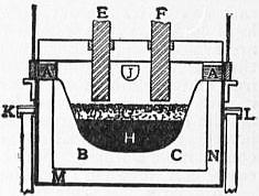
Fig. 23.—Heroult Double-arc Electric Steel Purifying Furnace.
108. Electric steel-making processes, or more accurately processes in which electrically heated furnaces are used, have developed very rapidly. In steel-making, electric furnaces are used for two distinct purposes, first for making steel sufficiently better than Bessemer and open-hearth steels to replace these for certain important purposes, and second for replacing the very expensive crucible process for making the very best steel. The advantages of the electric furnaces for these purposes can best be understood after examining the furnaces themselves and the way in which they are used. The most important ones are either “arc” furnaces, i.e. those heated by electric arcs, or “induction” ones, i.e. those in which the metal under treatment is heated by its own resistance to a current of electricity induced in it from without. The Heroult furnace, the best known in the arc class, and the Kjellin and Roechling-Rodenhauser furnaces, the best known of the induction class, will serve as examples.
The Heroult furnace (fig. 23) is practically a large closed crucible, ABCA, with two carbon electrodes, E and F, “in series” with the bath, H, of molten steel. A pair of electric arcs play between these electrodes and the molten steel, passing through the layer of slag, G, and generating much heat. The lining of the crucible may be of either magnesite (MgO) or chromite (FeO·Cr2O3). The whole furnace, electrodes and all, rotates about the line KL for the purpose of pouring out the molten slag and purified metal through the spout J at the end of the process. This spout and the charging doors A, A are kept closed except when in actual use for pouring or charging.
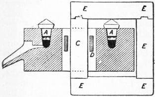
Fig. 24.—Kjellin Induction Electric Steel Melting Furnace.
The Kjellin furnace consists essentially of an annular trough, AA (fig. 24), which contains the molten charge. This charge is heated, like the filaments of a common household electric lamp, by the resistance which it offers to the passage of a current of electricity induced in it by means of the core C and the frame EEE. The ends of this core are connected above, below and at the right of the trough A, by means of that frame, so that the trough and this core and frame stand to each other in a position like that of two successive links of a common oval-linked chain. A current of great electromotive force (intensity or voltage) passed through the coil D, induces, by means of the core and frame, a current of enormous quantity (volume or amperage), but very small electromotive force, in the metal in the trough. Thus the apparatus is analogous to the common transformers used for inducing from currents of great electromotive force and small quantity, which carry energy through long distances, currents of great quantity and small electromotive force for incandescent lights and for welding. The molten metal in the Kjellin trough forms the “secondary” circuit. Like the Heroult furnace, the Kjellin furnace may be lined with either magnesite or chromite, and it may be tilted for the purpose of pouring off slag and metal.
The shape which the molten metal under treatment has in the Kjellin furnace, a thin ring of large diameter, is evidently bad, inconvenient for manipulation and with excessive heat-radiating surface. In the Roechling-Rodenhauser induction furnace (fig. 25), the molten metal lies chiefly in a large compact mass A, heated at three places on its periphery by the current induced in it there by means of the three coils and cores CCC. The molten metal also extends round each of these three coils, in the narrow channels B. It is in the metal in these channels and in that part of the main mass of metal which immediately adjoins the coils that the current is induced by means of the coils and cores, as in the Kjellin furnace.
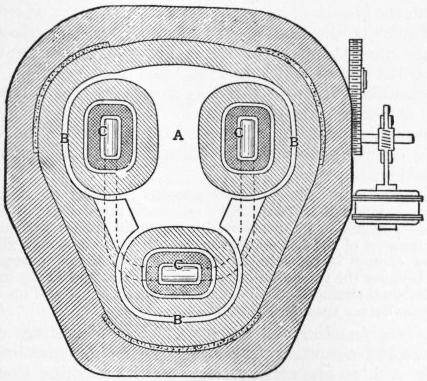
Fig. 25.—Plan of Roechling-Rodenhauser Induction Electric Furnace.
When the Heroult furnace is used for completing the purification of molten steel begun in the Bessemer or open-hearth process, and this is its most appropriate use, the process carried out in it may be divided into two stages, first dephosphorization, and second deoxidation and desulphurization.
In the first stage the phosphorus is removed from the molten steel by oxidizing it to phosphoric acid, P2O5, by means of iron oxide contained in a molten slag very rich in lime, and hence very basic and retentive of that phosphoric acid. This slag is formed by melting lime and iron oxide, with a little silica sand if need be. Floating on top of the molten metal, it rapidly oxidizes its phosphorus, and the resultant phosphoric acid combines with the lime in the overlying slag as phosphate of lime. When the removal of the phosphorus is sufficiently complete, this slag is withdrawn from the furnace.
Next comes the deoxidizing and desulphurizing stage, of which the first step is to throw some strongly deoxidizing substance, such as coke or ferro-silicon, upon the molten metal, in order to remove thus the chief part of the oxygen which it has taken up during the oxidation of the phosphorus in the preceding stage. Next the metal is covered with a very basic slag, made by melting lime with a little silica and fluor spar. Coke now charged into this slag first deoxidizes any iron oxide contained in either slag or metal, and next deoxidizes part of the lime of the slag and thus forms calcium, which, uniting with the sulphur present in the molten metal, forms calcium sulphide, CaO + FeS + C = CaS + Fe + CO. This sulphide is nearly insoluble in the metal, but is readily soluble in the overlying basic slag, into which it therefore passes. The thorough removal of the sulphur is thus brought about by the deoxidation of the calcium. It is by forming calcium sulphide that sulphur is removed in the manufacture of pig iron in the iron blast furnace, in the crucible of which, as in the electric furnaces, the conditions are strongly deoxidizing. But in the Bessemer and open-hearth processes this means of removing sulphur cannot be used, because in each of them there is always enough oxygen in the atmosphere to re-oxidize any calcium as fast as it is deoxidized. Here sulphur may indeed be removed to a very important degree in the form of manganese sulphide, which distributes itself between metal and slag in rough accord with the laws of equilibrium. But if we rely on this means we have difficulty in reducing the sulphur content of the metal to 0.03% and very great difficulty in reducing it to 0.02%, whereas with the calcium sulphide of the electric furnaces we can readily reduce it to less than 0.01%.
When the desulphurization is sufficiently complete, the sulphur-bearing slag is removed, the final additions needed to give the metal exactly the composition aimed at are made, and the molten steel is tapped out of the furnace into its moulds. If the initial quantity of phosphorus or sulphur is large, or if the removal of these impurities is to be made very thorough, the dephosphorizing or the desulphurizing slagging off may be repeated. While the metal lies tranquilly on the bottom of the furnace, any slag mechanically suspended in it has a chance to rise to the surface and unite with the slag layer above.
In addition to this work of purification, the furnace may be used for melting down the initial charge of cold metal, and for beginning the purification—in short not only for finishing but also for roughing. But this is rarely expedient, because electricity is so expensive that it should be used for doing only those things which cannot be accomplished by any other and cheaper means. The melting can be done much more cheaply in a cupola or open-hearth furnace, and the first part of the purification much more cheaply in a Bessemer converter or open-hearth furnace.
The normal use of the Kjellin induction furnace is to do the work usually done in the crucible process, i.e. to melt down very pure iron for the manufacture of the best kinds of steel, such as fine tool and spring steel, and to bring the molten metal simultaneously to the exact composition and temperature at which it should be cast into its moulds. This furnace may be used also for purifying the molten metal, but it is not so well suited as the arc furnaces for dephosphorizing. The reason for this is that in it the slag, by means of which all the purification must needs be done, is not heated effectively; that hence it is not readily made thoroughly liquid; that hence the removal of the phosphoric slag made in the early dephosphorizing stage of the process is liable to be incomplete; and that hence, finally, the phosphorus of any of this slag which is left in the furnace becomes deoxidized during the second or deoxidizing stage, and is thereby returned to befoul the underlying steel. The reason why the slag is not heated effectively is that the heat is developed only in the layer of metal itself, by its resistance to the induced current, and hence the only heat which the slag receives is that supplied to its lower surface by the metal, while its upper side is constantly radiating heat away towards the relatively cool roof above.
The Roechling-Rodenhauser furnace is unfitted, by the vulnerability of its interior walls, for receiving charges of cold metal to be melted down, but it is used to good advantage for purifying molten basic Bessemer steel sufficiently to fit it for use in the form of railway rails.
We are now in a position to understand why electricity should be used as a source of heat in making molten steel. Electric furnaces are at an advantage over others as regards the removal of sulphur and of iron oxide from the molten steel, because their atmosphere is free from the sulphur always present in the flame of coal-fired furnaces, and almost free from oxygen, because this element is quickly absorbed by the carbon and silicon of the steel, and in the case of arc furnaces by the carbon of the electrodes themselves, and is replaced only very slowly by leakage, whereas through the Bessemer converter and the open-hearth furnace a torrent of air is always rushing. As we have seen, the removal of sulphur can be made complete only by deoxidizing calcium, and this cannot be done if much oxygen is present. Indeed, the freedom of the atmosphere of the electric furnaces from oxygen is also the reason indirectly why the molten metal can be freed from mechanically suspended slag more perfectly in them than in the Bessemer converter or the open-hearth furnace. In order that this finely divided slag shall rise to the surface and there coalesce with the overlying layer, the metal must be tranquil. But tranquillity is clearly impossible in the Bessemer converter, in which the metal can be kept hot only by being torn into a spray by the blast. It is practically unattainable in the open-hearth furnace, because here the oxygen of the furnace atmosphere indirectly oxidizes the carbon of the metal which is kept boiling by the escape of the resultant carbonic oxide. In short the electric furnaces can be used to improve the molten product of the Bessemer converter and open-hearth furnace, essentially because their atmosphere is free from sulphur and oxygen, and because they can therefore remove sulphur, iron oxide and mechanically suspended slag, more thoroughly than is possible in these older furnaces. They make a better though a dearer steel.
Further, the electric furnaces, e.g. the Kjellin, can be used to replace the crucible melting process (§ 106), chiefly because their work is cheaper for two reasons. First, they treat a larger charge, a ton or more, whereas the charge of each crucible is only about 80 pounds. Second, their heat is applied far more economically, directly to the metal itself, whereas in the crucible process the heat is applied most wastefully to the outside of the non-conducting walls of a closed crucible within which the charge to be heated lies. Beyond this sulphur and phosphorus can be removed in the electric furnace, whereas in the crucible process they cannot. In short electric furnaces replace the old crucible furnace primarily because they work more cheaply, though in addition they may be made to yield a better steel than it can.
Thus we see that the purification in these electric furnaces has nothing to do with electricity. We still use the old familiar purifying agents, iron oxide, lime and nascent calcium. The electricity is solely a source of heat, free from the faults of the older sources which for certain purposes it now replaces. The electric furnaces are likely to displace the crucible furnaces completely, because they work both more cheaply and better. They are not likely to displace either the open-hearth furnace or the Bessemer converter, because their normal work is only to improve the product of these older furnaces. Here their use is likely to be limited by its costliness, because for the great majority of purposes the superiority of the electrically purified steel is not worth the cost of the electric purification.
109. Electric Ore-smelting Processes.—Though the electric processes which have been proposed for extracting the iron from iron ore, with the purpose of displacing the iron blast furnace, have not become important enough to deserve description here, yet it should be possible to devise one which would be useful in a place (if there is one) which has an abundance of water power and iron ore and a local demand for iron, but has not coke, charcoal or bituminous coal suitable for the blast furnace. But this ancient furnace does its fourfold work of deoxidizing, melting, removing the gangue and desulphurizing, so very economically that it is not likely to be driven out in other places until the exhaustion of our coal-fields shall have gone so far as to increase the cost of coke greatly.
110. Comparison of Steel-making Processes.—When Bessemer discovered that by simply blowing air through molten cast iron rapidly he could make low-carbon steel, which is essentially wrought iron greatly improved by being freed from its essential defect, its necessarily weakening and embrittling slag, the very expensive and exhausting puddling process seemed doomed, unable to survive the time when men should have familiarized themselves with the use of Bessemer steel, and should have developed the evident possibilities of cheapness of the Bessemer process. Nevertheless the use of wrought iron actually continued to increase. The first of the United States decennial censuses to show a decrease in the production of wrought iron was that in 1890, 35 years after the invention of the Bessemer process. It is still in great demand for certain normal purposes for which either great ease in welding or resistance to corrosion by rusting is of great importance; for purposes requiring special forms of extreme ductility which are not so confidently expected in steel; for miscellaneous needs of many users, some ignorant, some very conservative; and for remelting in the crucible process. All the best cutlery and tool steel is made either by the crucible process or in electric furnaces, and indeed all for which any considerable excellence is claimed is supposed to be so made, though often incorrectly. But the great mass of the steel of commerce is made by the Bessemer and the open-hearth processes. Open-hearth steel is generally thought to be better than Bessemer, and the acid variety of each of these two processes is thought to yield a better product than the basic variety. This may not necessarily be true, but the acid variety lends itself more readily to excellence than the basic. A very large proportion of ores cannot be made to yield cast iron either free enough from phosphorus for the acid Bessemer or the acid open-hearth process, neither of which removes that most injurious element, or rich enough in phosphorus for the basic Bessemer process, which must rely on that element as its source of heat. But cast iron for the basic open-hearth process can be made from almost any ore, because its requirements, comparative freedom from silicon and sulphur, depend on the management of the blast-furnace rather than on the composition of the ore, whereas the phosphorus-content of the cast iron depends solely on that of the ore, because nearly all the phosphorus of the ore necessarily passes into the cast iron. Thus the basic open-hearth process is the only one which can make steel from cast iron containing more than 0.10% but less than 1.80% of phosphorus.
The restriction of the basic Bessemer process to pig iron containing at least 1.80% of phosphorus has prevented it from getting a foothold in the United States; the restriction of the acid Bessemer process to pig iron very low in phosphorus, usually to that containing less than 0.10% of that element, has almost driven it out of Germany, has of late retarded, indeed almost stopped, the growth of its use in the United States, and has even caused it to be displaced at the great Duquesne works of the Carnegie Steel Company by the omnivorous basic open-hearth process, the use of which has increased very rapidly. Under most conditions the acid Bessemer process is the cheapest in cost of conversion, the basic Bessemer next, and the acid open-hearth next, though the difference between them is not great. But the crucible process is very much more expensive than any of the others.
Until very lately the Bessemer process, in either its acid or its basic form, made all of the world’s rail steel; but even for this work it has now begun to be displaced by the basic open-hearth process, partly because of the fast-increasing scarcity of ores which yield pig iron low enough in phosphorus for the acid Bessemer process, and partly because the increase in the speed of trains and in the loads on the individual engine- and car-wheels has made a demand for rails of a material better than Bessemer steel.
111. Iron founding, i.e. the manufacture of castings of cast iron, consists essentially in pouring the molten cast iron into moulds, and, as preparatory steps, melting the cast iron itself and preparing the moulds. These are usually made of sand containing enough clay to give it the needed coherence, but of late promising attempts have been made to use permanent iron moulds. In a very few places the molten cast iron as it issues from the blast furnace is cast directly in these moulds, but in general it is allowed to solidify in pigs, and then remelted either in cupola furnaces or in air furnaces. The cupola furnace (fig. 26) is a shaft much like a miniature blast furnace, filled from top to bottom by a column of lumps of coke and of iron. The blast of air forced in through the tuyeres near the bottom of the furnace burns the coke there, and the intense heat thus caused melts away the surrounding iron, so that this column of coke and iron gradually descends; but it is kept at its full height by feeding more coke and iron at its top, until all the iron needed for the day’s work has thus been charged. As the iron melts it runs out through a tap hole and spout at the bottom of the furnace, to be poured into the moulds by means of clay-lined ladles. The air furnace is a reverberatory furnace like that used for puddling (fig. 14), but larger, and in it the pigs of iron, lying on the bottom or hearth, are melted down by the flame from the coal which burns in the firebox. The iron is then held molten till it has grown hot enough for casting and till enough of its carbon has been burnt away to leave just the carbon-content desired, and it is then tapped out and poured into the moulds.
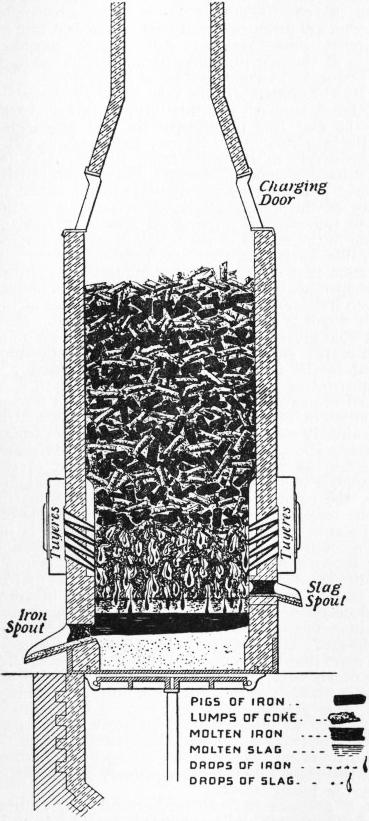
Fig. 26.—Cupola Furnace for Remelting Pig Iron.
Of the two the cupola is very much the more economical of fuel, thanks to the direct transfer of heat from the burning coke to the pig iron with which it is in contact. But this contact both causes the iron to absorb sulphur from the coke to its great harm, and prevents it from having any large part of its carbon burnt away, which in many cases would improve it very greatly by strengthening it. Thus it comes about that the cupola, because it is so economical, is used for all but the relatively few cases in which the strengthening of the iron by the removal of part of its carbon and the prevention of the absorption of sulphur are so important as to compensate for the greater cost of the air-furnace melting.
112. Cast iron for foundry purposes, i.e. for making castings of cast iron. Though, as we have seen in § 19, steel is rarely given a carbon-content greater than 1.50% lest its brittleness should be excessive, yet cast iron with between 3 and 4% of carbon, the usual cast iron of the foundry, is very useful. Because of the ease and cheapness with which, thanks to its fluidity and fusibility (fig. 1), it can be melted and run even into narrow and intricate moulds, castings made of it are very often more economical, i.e. they serve a given purpose more cheaply, in the long run, than either rolled or cast steel, in spite of their need of being so massive that the brittleness of the material itself shall be endurable. Indeed this high carbon-content, 3 to 4%, in practice actually leads to less brittleness than can readily be had with somewhat less carbon, because with it much of the carbon can easily be thrown into the relatively harmless state of graphite, whereas if the carbon amounts to less than 3% it can be brought to this state only with difficulty. For crushing certain kinds of rock, the hardness of which cast iron is capable really makes it more valuable, pound for pound, than steel.
113. Qualities needed in Cast Iron Castings.—Different kinds of castings need very different sets of qualities, and the composition of the cast iron itself must vary from case to case so as to give each the qualities needed. The iron for a statuette must first of all be very fluid, so that it will run into every crevice in its mould, and it must expand in solidifying, so that it shall reproduce accurately every detail of that mould. The iron for most engineering purposes needs chiefly to be strong and not excessively brittle. That for the thin-walled water mains must combine strength with the fluidity needed to enable it to run freely into its narrow moulds; that for most machinery must be soft enough to be cut easily to an exact shape; that for hydraulic cylinders must combine strength with density lest the water leak through; and that for car-wheels must be intensely hard in its wearing parts, but in its other parts it must have that shock-resisting power which can be had only along with great softness. Though all true cast iron is brittle, in the sense that it is not usefully malleable, i.e. that it cannot be hammered from one shape into another, yet its degree of brittleness differs as that of soapstone does from that of glass, so that there are the intensely hard and brittle cast irons, and the less brittle ones, softer and unhurt by a shock which would shiver the former.
Of these several qualities which cast iron may have, fluidity is given by keeping the sulphur-content low and phosphorus-content high; and this latter element must be kept low if shock is to be resisted; but strength, hardness, endurance of shock, density and expansion in solidifying are controlled essentially by the distribution of the carbon between the states of graphite and cementite, and this in turn is controlled chiefly by the proportion of silicon, manganese and sulphur present, and in many cases by the rate of cooling.
114. Constitution of Cast Iron.—Cast iron naturally has a high carbon-content, usually between 3 and 4%, because while molten it absorbs carbon greedily from the coke with which it is in contact in the iron blast furnace in which it is made, and in the cupola furnace in which it is remelted for making most castings. This carbon may all be present as graphite, as in typical grey cast iron; or all present as cementite, Fe3C, as in typical white cast iron; or, as is far more usual, part of it may be present as graphite and part as cementite. Now how does it come about that the distribution of the carbon between these very unlike states determines the strength, hardness and many other valuable properties of the metal as a whole? The answer to this is made easy by a careful study of the effect of this same distribution on the constitution of the metal, because it is through controlling this constitution that the condition of the carbon controls these useful properties. To fix our ideas let us assume that the iron contains 4% of carbon. If this carbon is all present as graphite, so that in cooling the graphite-austenite diagram has been followed strictly (§ 26), the constitution is extremely simple; clearly the mass consists first of a metallic matrix, the carbonless iron itself with whatever silicon, manganese, phosphorus and sulphur happen to be present, in short an impure ferrite, encased in which as a wholly distinct foreign body is the graphite. The primary graphite (§ 26) generally forms a coarse, nearly continuous skeleton of curved black plates, like those shown in fig. 27; the eutectic graphite is much finer; while the pro-eutectoid and eutectoid graphite, if they exist, are probably in very fine particles. We must grasp clearly this conception of metallic matrix and encased graphite skeleton if we are to understand this subject.
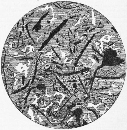
Fig. 27.—Graphite in Grey Cast Iron.
Now this matrix itself is equivalent to a very low-carbon steel, strictly speaking to a carbonless steel, because it consists of pure ferrite, which is just what such a steel consists of; and the cast iron as a whole is therefore equivalent to a matrix of very low-carbon steel in which is encased a skeleton of graphite plates, besides some very fine scattered particles of graphite.
Next let us imagine that, in a series of cast irons all containing 4% of carbon, the graphite of the initial skeleton changes gradually into cementite and thereby becomes part of the matrix, a change which of course has two aspects, first, a gradual thinning of the graphite skeleton and a decrease of its continuity, and second, a gradual introduction of cementite into the originally pure ferrite matrix. By the time that 0.4% of graphite has thus changed, and in changing has united with 0.4 × 14 = 5.6% of the iron of the original ferrite matrix, it will have changed this matrix from pure ferrite into a mixture of
Cementite 0.4 + 5.6 = 6.0
Ferrite 96.0 − 5.6 = 90.4
——
96.4
The residual graphite skeleton forms 4 − 0.4 = 3.6
——
100.0
But this matrix is itself equivalent to a steel of about 040% of carbon (more accurately 0.40 × 100 ÷ 96.4 = 0.415%), a rail steel, because it is of just such a mixture of ferrite and cementite in the ratio of 90.4 : 6 or 94% and 6%, that such a rail steel consists. The mass as a whole, then, consists of 96.4 parts of metallic matrix, which itself is in effect a 0.415% carbon rail steel, weakened and embrittled by having its continuity broken up by this skeleton of graphite forming 3.6% of the whole mass by weight, or say 12% by volume.
As, in succeeding members of this same series of cast irons, more of the graphite of the initial skeleton changes into cementite and thereby becomes part of the metallic matrix, so the graphite skeleton becomes progressively thinner and more discontinuous, and the matrix richer in cementite and hence in carbon and hence equivalent first to higher and higher carbon steel, such as tool steel of 1% carbon, file steel of 1.50%, wire-die steel of 2% carbon and then to white cast iron, which consists essentially of much cementite with little ferrite. Eventually, when the whole of the graphite of the skeleton has changed into cementite, the mass as a whole becomes typical or ultra white cast iron, consisting of nothing but ferrite and cementite, distributed as follows (see fig. 2):—
Eutectoid ferrite 40.0
Eutectoid cementite 6.7
——
Eutectoid Interstratified as pearlite 46.7
Cementite, primary, eutectoid and pro-eutectoid 53.3
——
100.0
Total ferrite 40.0
Total cementite 60.0
——
100.0
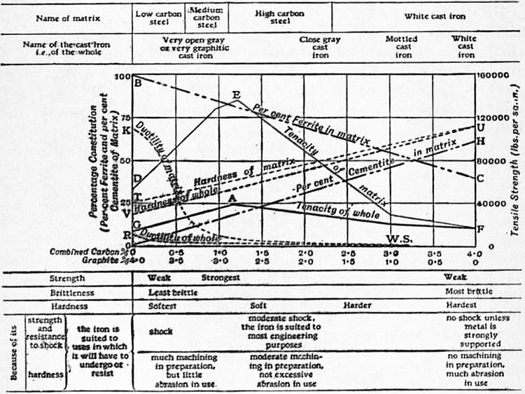
Fig. 28.—Physical Properties and assumed Microscopic Constitution of Cast Iron containing 4% of carbon, as affected by the distribution of that carbon between the combined and graphitic states.
The constitution and properties of such a series of cast irons, all containing 4% of carbon but with that carbon shifting progressively from the state of graphite to that of cementite as we pass from specimen to specimen, may, with the foregoing picture of a skeleton-holding matrix clearly in our minds be traced by means of fig. 28. The change from graphite into cementite is supposed to take place as we pass from left to right. BC and OH give the proportion of ferrite and cementite respectively in the matrix, DEF, KS and TU reproduced from fig. 3 give the consequent properties of the matrix, and GAF, RS and VU give, partly from conjecture, the properties of the cast iron as a whole. Above the diagram are given the names of the different classes of cast iron to which different stages in the change from graphite to cementite correspond, and above these the names of kinds of steel or cast iron, to which at the corresponding stages the constitution of the matrix corresponds, while below the diagram are given the properties of the cast iron as a whole corresponding to these stages, and still lower the purposes for which these stages fit the cast iron, first because of its strength and shock-resisting power, and second because of its hardness.
115. Influence of the Constitution of Cast Iron on its Properties.—How should the hardness, strength and ductility, or rather shock-resisting power, of the cast iron be affected by this progressive change from graphite into cementite? First, the hardness (VU) should increase progressively as the soft ferrite and graphite are replaced by the glass-hard cementite. Second, though the brittleness should be lessened somewhat by the decrease in the extent to which the continuity of the strong matrix is broken up by the graphite skeleton, yet this effect is outweighed greatly by that of the rapid substitution in the matrix of the brittle cementite for the very ductile copper-like ferrite, so that the brittleness increases continuously (RS), from that of the very grey graphitic cast irons, which, like that of soapstone, is so slight that the metal can endure severe shock and even indentation without breaking, to that of the pure white cast iron which is about as brittle as porcelain. Here let us recognize that what gives this transfer of carbon from graphite skeleton to metallic matrix such very great influence on the properties of the metal is the fact that the transfer of each 1% of carbon means substituting in the matrix no less than 15% of the brittle, glass-hard cementite for the soft, very ductile ferrite. Third, the tensile strength of steel proper, of which the matrix consists, as we have already seen (fig. 3), increases with the carbon-content till this reaches about 1.25%, and then in turn decreases (fig. 28, DEF). Hence, as with the progressive transfer of the carbon from the graphitic to the cementite state in our imaginary series of cast irons, the combined carbon present in the matrix increases, so does the tensile strength of the mass as a whole for two reasons; first, because the strength of the matrix itself is increasing (DE), and second, because the discontinuity is decreasing with the decreasing proportion of graphite. With further transfer of the carbon from the graphitic to the combined state, the matrix itself grows weaker (EF); but this weakening is offset in a measure by the continuing decrease of discontinuity due to the decreasing proportion of graphite. The resultant of these two effects has not yet been well established; but it is probable that the strongest cast iron has a little more than 1% of carbon combined as cementite, so that its matrix is nearly equivalent to the strongest of the steels. As regards both tensile strength and ductility not only the quantity but the distribution of the graphite is of great importance. Thus it is extremely probable that the primary graphite, which forms large sheets, is much more weakening and embrittling than the eutectic and other forms, and therefore that, if either strength or ductility is sought, the metal should be free from primary graphite, i.e. that it should not be hyper-eutectic.
The presence of graphite has two further and very natural effects. First, if the skeleton which it forms is continuous, then its planes of junction with the metallic matrix offer a path of low resistance to the passage of liquids or gases, or in short they make the metal so porous as to unfit it for objects like the cylinders of hydraulic presses, which ought to be gas-tight and water-tight. For such purposes the graphite-content should be low. Second, the very genesis of so bulky a substance as the primary and eutectic graphite while the metal is solidifying (fig. 5) causes a sudden and permanent expansion, which forces the metal into even the finest crevices in its mould, a fact which is taken advantage of in making ornamental castings and others which need great sharpness of detail, by making them rich in graphite.
To sum this up, as graphite is replaced by carbon combined as cementite, the hardness, brittleness and density increase, and the expansion in solidification decreases, in both cases continuously, while the tensile strength increases till the combined carbon-content rises a little above 1%, and then in turn decreases. That strength is good and brittleness bad goes without saying; but here a word is needed about hardness. The expense of cutting castings accurately to shape, cutting on them screw threads and what not, called “machining” in trade parlance, is often a very large part of their total cost; and it increases rapidly with the hardness of the metal. On the other hand, the extreme hardness of nearly graphiteless cast iron is of great value for objects of which the chief duty is to resist abrasion, such as parts of crushing machinery. Hence objects which need much machining are made rich in graphite, so that they may be cut easily, and those of the latter class rich in cementite so that they may not wear out.
116. Means of controlling the Constitution of Cast Iron.—The distribution of the carbon between these two states, so as to give the cast iron the properties needed, is brought about chiefly by adjusting the silicon-content, because the presence of this element favours the formation of graphite. Beyond this, rapid cooling and the presence of sulphur both oppose the formation of graphite, and hence in cast iron rich in sulphur, and in thin and therefore rapidly cooling castings, the silicon-content must be greater than in thick ones and in those freer from sulphur. Thus thick machinery castings usually contain between 1.50 and 2.25% of silicon, whereas thin castings and ornamental ones which must reproduce the finest details of the mould accurately may have as much as 3 or even 3.40% of it. Castings which, like hydraulic press cylinders and steam radiators, must be dense and hence must have but little graphite lest their contents leak through their walls, should not have more than 1.75% of silicon and may have even as little as 1% if impenetrability is so important that softness and consequent ease of machining must be sacrificed to it. Cast iron railroad car-wheels, the tread or rim of which must be intensely hard so as to endure the grinding action of the brakeshoe while their central parts must have good shock-resisting power, are given such moderate silicon-content, preferably between 0.50 and 0.80%, as in and by itself leaves the tendencies toward graphite-forming and toward cementite-forming nearly in balance, so that they are easily controlled by the rate of cooling. The “tread” or circumferential part of the mould itself is made of iron, because this, by conducting the heat away from the casting rapidly, makes it cool quickly, and thus causes most of the carbon here to form cementite, and thus in turn makes the tread of the wheel intensely hard; while those parts of the mould which come in contact with the central parts of the wheel are made of sand, which conducts the heat away from the molten metal so slowly that it solidifies slowly, with the result that most of its carbon forms graphite, and here the metal is soft and shock-resisting.
117. Influence of Sulphur.—Sulphur has the specific harmful effects of shifting the carbon from the state of graphite to that of cementite, and thus of making the metal hard and brittle; of making it thick and sluggish when molten, so that it does not run freely in the moulds; and of making it red short, i.e. brittle at a red heat, so that it is very liable to be torn by the aeolotachic contraction in cooling from the molten state; and it has no good effects to offset these. Hence the sulphur present is, except in certain rare cases, simply that which the metallurgist has been unable to remove. The sulphur-content should not exceed 0.12%, and it is better that it should not exceed 0.08 % in castings which have to be soft enough to be machined, nor 0.05% in thin castings the metal for which must be very fluid.
118. Influence of Manganese.—Manganese in many cases, but not in all, opposes the formation of graphite and thus hardens the iron, and it lessens the red shortness (§ 40), which sulphur causes, by leading to the formation of the less harmful manganese sulphide instead of the more harmful iron sulphide. Hence the manganese-content needed increases with the sulphur-content which has to be endured. In the better classes of castings it is usually between 0.40 and 0.70%, and in chilled railroad car-wheels it may well be between 0.15 and 0.30%; but skilful founders, confronted with the task of making use of cast iron rich in manganese, have succeeded in making good grey iron castings with even as much as 2.20% of this element.
119. Influence of Phosphorus.—Phosphorus has, along with its great merit of giving fluidity, the grave defect of causing brittleness, especially under shock. Fortunately its embrittling effect on cast iron is very much less than on steel, so that the upper limit or greatest tolerable proportion of phosphorus, instead of being 0.10 or better 0.08% as in the case of rail steel, may be put at 0.50% in case of machinery castings even if they are exposed to moderate shocks; at 1.60% for gas and water mains in spite of the gravity of the disasters which extreme brittleness here might cause; and even higher for castings which are not exposed to shock, and are so thin that the iron of which they are made must needs be very fluid. The permissible phosphorus-content is lessened by the presence of either much sulphur or much manganese, and by rapid cooling, as for instance in case of thin castings, because each of these three things, by leading to the formation of the brittle cementite, in itself creates brittleness which aggravates that caused by phosphorus.
120. Defects in Steel Ingots.—Steel ingots and other steel castings are subject to three kinds of defects so serious as to deserve notice here. They are known as “piping,” “blowholes” and “segregation.”
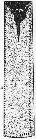
Fig. 29.—Diagram showing how a Pipe is formed.
A, Superficial blowholes. B, Deep-seated blowholes. C, Pipe.
121. Piping.—In an early period of the solidification of a molten steel ingot cast in a cold iron mould we may distinguish three parts: (1) the outer layers, i.e. the outermost of the now solid metal; (2) the inner layers, i.e. the remainder of the solid metal; and (3) the molten lake, i.e. the part which still is molten. At this instant the outer layers, because of their contact with the cold mould, are cooling much faster than the inner ones, and hence tend to contract faster. But this excess of their contraction is resisted by the almost incompressible inner layers so that the outer layers are prevented from contracting as much as they naturally would if unopposed, and they are thereby virtually stretched. Later on the cooling of the inner layers becomes more rapid than that of the outer ones, and on this account their contraction tends to become greater than that of the outer ones. Because the outer and inner layers are integrally united, this excess of contraction of the inner layers makes them draw outward towards and against the outer layers, and because of their thus drawing outward the molten lake within no longer suffices to fill completely the central space, so that its upper surface begins to sink. This ebb continues, and, combined with the progressive narrowing of the molten lake as more and more of it solidifies and joins the shore layers, gives rise to the pipe, a cavity like an inverted pear, as shown at C in fig. 29. Because this pipe is due to the difference in the rates of contraction of interior and exterior, it may be lessened by retarding the cooling of the mass as a whole, and it may be prevented from stretching down deep by retarding the solidification of the upper part of the ingot, as, for instance, by preheating the top of the mould, or by covering the ingot with a mass of burning fuel or of molten slag. This keeps the upper part of the mass molten, so that it continues to flow down and feed the pipe during the early part of its formation in the lower and quicker-cooling part of the ingot. In making castings of steel this same difficulty arises; and much of the steel-founder’s skill consists either in preventing these pipes, or in so placing them that they shall not occur in the finished casting, or at least not in a harmful position. In making armour-plates from steel ingots, as much as 40% of the metal may be rejected as unsound from this cause. An ingot should always stand upright while solidifying, so that the unsound region due to the pipe may readily be cut off, leaving the rest of the ingot solid. If the ingot lay on its side while solidifying, the pipe would occur as shown in fig. 30, and nearly the whole of the ingot would be unsound.
122. Blowholes.—Iron, like water and many other substances, has a higher solvent power for gases, such as hydrogen and nitrogen, when molten, i.e. liquid, than when frozen, i.e. solid. Hence in the act of solidifying it expels any excess of gas which it has dissolved while liquid, and this gas becomes entangled in the freezing mass, causing gas bubbles or blowholes, as at A and B in fig. 29. Because the volume of the pipe represents the excess of the contraction of the inner walls and the molten lake jointly over that of the outer walls, between the time when the lake begins to ebb and the time when even the axial metal is too firm to be drawn further open by this contraction, the space occupied by blowholes must, by compensating for part of this excess, lessen the size of the pipe, so that the more abundant and larger the blowholes are, the smaller will the pipe be. The interior surface of a blowhole which lies near the outer crust of the ingot, as at A in fig. 29, is liable to become oxidized by the diffusion of the atmospheric oxygen, in which case it can hardly be completely welded later, since welding implies actual contact of metal with metal; it thus forms a permanent flaw. But deep-seated blowholes like those at B are relatively harmless in low-carbon easily welding steel, because the subsequent operation of forging or rolling usually obliterates them by welding their sides firmly together.
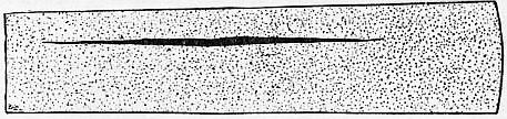
Fig. 30.—Diagram showing a Pipe so formed as to render Ingot unsound.
Blowholes may be lessened or even wholly prevented by adding to the molten metal shortly before it solidifies either silicon or aluminium, or both; even as little as 0.002% of aluminium is usually sufficient. These additions seem to act in part by deoxidizing the minute quantity of iron oxide and carbonic oxide present, in part by increasing the solvent power of the metal for gas, so that even after freezing it can retain in solution the gas which it had dissolved when molten. But, because preventing blowholes increases the volume of the pipe, it is often better to allow them to form, but to control their position, so that they shall be deep-seated. This is done chiefly by casting the steel at a relatively low temperature, and by limiting the quantity of manganese and silicon which it contains. Brinell finds that, for certain normal conditions, if the sum of the percentage of manganese plus 5.2 times that of the silicon equals 1.66, there will be no blowholes; if this sum is less, blowholes will occur, and will be injuriously near the surface unless this sum is reduced to 0.28. He thus finds that this sum should be either as great as 1.66, so that blowholes shall be absent; or as low as 0.28, so that they shall be harmlessly deep-seated. These numbers must be varied with the variations in other conditions, such as casting temperature, rapidity of solidification, &c.
123. Segregation.—The solidification of an ingot of steel takes place gradually from without inwards, and each layer in solidifying tends to expel into the still molten interior the impurities which it contains, especially the carbon, phosphorus, and sulphur, which by this process are in part concentrated or segregated in the last-freezing part of the ingot. This is in general around the lower part of the pipe, so that here is a second motive for rejecting the piped part of the ingot. While segregation injures the metal here, often fatally, by giving it an indeterminate excess of phosphorus and sulphur, it clearly purifies the remainder of the ingot, and on this account it ought, under certain conditions, to be promoted rather than restrained. The following is an extreme case:—
Carbon. Silicon. Manganese. Phosphorus. Sulphur.
Composition of the initial metal per cent 0.24 0.336 0.97 0.089 0.074
Composition of the segregate 1.27 0.41 1.08 0.753 0.418
The surprising fact that the degree of segregation does not increase greatly either with the slowness of solidification or with the size of the ingot, at least between the limits of 5 in. sq. and 16 in. sq., has been explained by the theory that the relative quiet due to the gentleness of the convection currents in a slowly cooling mass favours the formation of far outshooting pine-tree crystals, and that the tangled branches of these crystals landlock much of the littoral molten mother metal, and thus mechanically impede that centreward diffusion and convection of the impurities which is the essence of segregation.
124. Castings and Forgings.—There are two distinct ways of making the steel objects actually used in the arts, such as rails, gear wheels, guns, beams, &c., out of the molten steel made by the Bessemer, open hearth, or crucible process, or in an electric furnace. The first is by “steel founding,” i.e. casting the steel as a “steel casting” in a mould which has the exact shape of the object to be made, e.g. a gear wheel, and letting it solidify there. The second is by casting it into a large rough block called an “ingot,” and rolling or hammering this out into the desired shape. Though the former certainly seems the simpler way, yet its technical difficulties are so great that it is in fact much the more expensive, and therefore it is in general used only in making objects of a shape hard to give by forging or rolling. These technical difficulties are due chiefly to the very high melting point of the metal, nearly 1500° C (2732° F.), and to the consequent great contraction which it undergoes in cooling through the long range between this temperature and that of the room. The cooling of the thinner, the outer, and in general the more exposed parts of the casting outruns that of the thicker and less exposed parts, with the consequence that, at any given instant, the different parts are contracting at very different rates, i.e. aeolotachically; and this aeolotachic contraction is very likely to concentrate severe stress on the slowest cooling parts at the time when they are passing from the molten to the solid state, when the steel is mushy, with neither the fluidity of a liquid nor the strength and ductility of a solid, and thus to tear it apart. Aeolotachic contraction further leads to the “pipes” or contraction cavities already described in § 121, and the procedure must be carefully planned first so as to reduce these to a minimum, and second so as to induce them to form either in those parts of the casting which are going to be cut off and re-melted, or where they will do little harm. These and kindred difficulties make each new shape or size a new problem, and in particular they require that for each and every individual casting a new sand or clay mould shall be made with care by a skilled workman. If a thousand like gears are to be cast, a thousand moulds must be made up, at least to an important extent by hand, for even machine moulding leaves something for careful manipulation by the moulder. It is a detail, one is tempted to say a retail, manufacture.
In strong contrast with this is the procedure in making rolled products such as rails and plates. The steel is cast in lots, weighing in some cases as much as 75 tons, in enduring cast iron moulds into very large ingots, which with their initial heat are immediately rolled down by a series of powerful roll trains into their final shape with but slight wear and tear of the moulds and the machinery. But in addition to the greater cost of steel founding as compared with rolling there are two facts which limit the use of steel castings: (1) they are not so good as rolled products, because the kneading which the metal undergoes in rolling improves its quality, and closes up its cavities; and (2) it would be extremely difficult and in most cases impracticable to cast the metal directly into any of the forms in which the great bulk of the steel of commerce is needed, such as rails, plates, beams, angles, rods, bars, and wire, because the metal would become so cool as to solidify before running far in such thin sections, and because even the short pieces which could thus be made would pucker or warp on account of their aeolotachic contraction.
125. Heating Furnaces are used in iron manufacture chiefly for bringing masses of steel or wrought iron to a temperature proper for rolling or forging. In order to economize power in these operations, the metal should in general be as soft and hence as hot as is consistent with its reaching a low temperature before the rolling or forging is finished, because, as explained in § 32, undisturbed cooling from a high temperature injures the metal. Many of the furnaces used for this heating are in a general way like the puddling furnace shown in fig. 14, except that they are heated by gas, that the hearth or bottom of the chamber in which they are heated is nearly flat, and that it is usually very much larger than that of a puddling furnace. But in addition there are many special kinds of furnaces arranged to meet the needs of each case. Of these two will be shown here, the Gjers soaking pit for steel ingots, and the Eckman or continuous furnace, as modified by C. H. Morgan for heating billets.
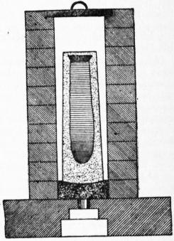
Fig. 31.—Section of Gjers Soaking Pit.
126. Gjers Soaking Pit.—When the outer crust of a large ingot in which a lot of molten steel has been cast has so far cooled that it can be moved without breaking, the temperature of the interior is still far above that suitable for rolling or hammering—so far above that the surplus heat of the interior would more than suffice to reheat the now cool crust to the rolling temperature, if we could only arrest or even greatly retard the further escape of heat from that crust. Bringing such an ingot, then, to the rolling temperature is not really an operation of heating, because its average temperature is already above the rolling temperature, but one of equalizing the temperature, by allowing the internal excess of heat to “soak” through the mass. Gjers did this by setting the partly-solidified ingot in a well-closed “pit” of brickwork, preheated by the excess heat of previous lots of ingots. The arrangement, shown in fig. 31, has three advantages—(1) that the temperature is adjusted with absolutely no consumption of fuel; (2) that the waste of iron due to the oxidation of the outer crust of the ingot is very slight, because the little atmospheric oxygen initially in the pit is not renewed, whereas in a common heating furnace the flame brings a constant fresh supply of oxygen; and (3) that the ingot remains upright during solidification, so that its pipe is concentrated at one end and is thus removable. (See § 121.) In this form the system is rather inflexible, for if the supply of ingots is delayed the pits grow unduly cool, so that the next ensuing lot of ingots either is not heated hot enough or is delayed too long in soaking. This defect is usually remedied by heating the pits by the Siemens regenerative system (see § 99); the greater flexibility thus gained outweighs the cost of the fuel used and the increased loss of iron by oxidation by the Siemens gas flame.
127. Continuous Heating Furnace.—The Gjers system is not applicable to small ingots or “billets,”5 because they lack the inner surplus heat of large ingots; indeed, they are now allowed to cool completely. To heat these on the intermittent plan for further rolling, i.e. to charge a lot of them as a whole in a heating furnace, bring them as a whole to rolling temperature, and then withdraw them as a whole for rolling, is very wasteful of heat, because it is only in the first part of the heating that the outside of the ingots is cool enough to abstract thoroughly the heat from the flame. During all the latter part of the heating, when the temperature of the ingot has approached that of the flame, only an ever smaller and smaller part of the heat of that flame can be absorbed by the ingots. Hence in the intermittent system most of the heat generated within the furnace escapes from it with the products of combustion. The continuous heating system (fig. 32) recovers this heat by bringing the flame into contact with successively cooler and cooler billets, A-F, and finally with quite cold ones, of consequently great heat-absorbing capacity.
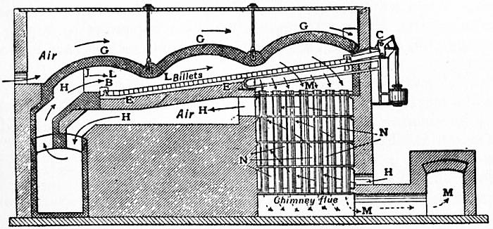
Fig. 32.—Diagram of C. H. Morgan’s Continuous Heating Furnace for 2-inch billets 30 ft. long.
A, Hottest billet ready for rolling. B, Exit door. C, Pusher, for forcing billets forward. D, Water-cooled pipe on which billets are pushed forward. E, Magnesite bricks on which the hot billets slide forward. F, The billet last entered. G, The suspended roof. H, The incoming air preheated by G and by the pipes N and brought from above G to between N by a flue not shown. J, The incoming gas. L, The flame. M, The escaping products of combustion. N, Pipes through which the products of combustion pass.
As soon as a hot billet A is withdrawn by pushing it endwise out of the exit door B, the whole row is pushed forward by a set of mechanical pushers C, the billets sliding on the raised water-cooled pipes D, and, in the hotter part of the furnace, on the magnesite bricks E, on which iron slides easily when red-hot. A new cold billet is then charged at the upper end of the hearth, and the new cycle begins by pushing out through B a second billet, and so forth. To lessen the loss in shape of “crop ends,” and for general economy, these billets are in some cases 30 ft. long, as in the furnace shown in fig. 32. It is to make it wide enough to receive such long billets that its roof is suspended, as here shown, by two sets of iron tie-rods. As the foremost end of the billet emerges from the furnace it enters the first of a series of roll-trains, and passes immediately thence to others, so that before half of the billet has emerged from the furnace its front end has already been reduced by rolling to its final shape, that of merchant-bars, which are relatively thin, round or square rods, in lengths of 300 ft.
Fig. 33.—Wire undergoing Reduction in the Die.
Fig. 34.—Two-high Rolling Mill.
In the intermittent system the waste heat can, it is true, be utilized either for raising steam (but inefficiently and inconveniently, because of the intermittency), or by a regenerative method like the Siemens, fig. 19; but this would probably recover less heat than the continuous system, first, because it transfers the heat from flame to metal indirectly instead of directly; and, second, because the brickwork of the Siemens system is probably a poorer heat-catcher than the iron billets of the continuous system, because its disadvantages of low conductivity and low specific heat probably outweigh its advantages of roughness and porosity.
128. Rolling, Forging, and Drawing.—The three chief processes for shaping iron and steel, rolling, forging (i.e. hammering, pressing or stamping) and drawing, all really proceed by squeezing the metal into the desired shape. In forging, whether under a hammer or under a press, the action is evidently a squeeze, however skilfully guided. In drawing, the pull of the pincers (fig. 33) upon the protruding end, F, of the rod, transmitted to the still undrawn part, E, squeezes the yielding metal of the rod against the hard unyielding die, C. As when a half-opened umbrella is thrust ferrule-foremost between the balusters of a staircase, so when the rod is drawn forward, its yielding metal is folded and forced backwards and centrewards by the resistance of the unyielding die, and thus it is reduced in diameter and simultaneously lengthened proportionally, without material change of volume or density.