VOLUME VIII slice III Destructor to Diameter (continued 4)
Reading edition
DHAR, a native state of India, in the Bhopawar agency, Central India. It includes many Rajput and Bhil feudatories, and has an area of 1775 sq. m. The raja is a Punwar Mahratta. The founder of the present ruling family was Anand Rao Punwar, a descendant of the great Paramara clan of Rajputs who from the 9th to the 13th century, when they were driven out by the Mahommedans, had ruled over Malwa from their capital at Dhar. In 1742 Anand Rao received Dhar as a fief from Baji Rao, the peshwa, the victory of the Mahrattas thus restoring the sovereign power to the family which seven centuries before had been expelled from this very city and country. Towards the close of the 18th and in the early part of the 19th century, the state was subject to a series of spoliations by Sindia and Holkar, and was only preserved from destruction by the talents and courage of the adoptive mother of the fifth raja. By a treaty of 1819 Dhar passed under British protection, and bound itself to act in subordinate co-operation. The state was confiscated for rebellion in 1857, but in 1860 was restored to Raja Anand Rao Punwar, then a minor, with the exception of the detached district of Bairusia, which was granted to the begum of Bhopal. Anand Rao, who received the personal title Maharaja and the K.C.S.I. in 1877, died in 1898, and was succeeded by Udaji Rao Punwar. In 1901 the population was 142,115. The state includes the ruins of Mandu, or Mandogarh, the Mahommedan capital of Malwa.
The Town of Dhar is 33 m. W. of Mhow, 908 ft. above the sea. Pop. (1901) 17,792. It is picturesquely situated among lakes and trees surrounded by barren hills, and possesses, besides its old walls, many interesting buildings, Hindu and Mahommedan, some of them containing records of a great historical importance. The Lat Masjid, or Pillar Mosque, was built by Dilawar Khan in 1405 out of the remains of Jain temples. It derives its name from an iron pillar, supposed to have been originally set up at the beginning of the 13th century in commemoration of a victory, and bearing a later inscription recording the seven days' visit to the town of the emperor Akbar in 1598. The pillar, which was 43 ft. high, is now overthrown and broken. The Kamal Maula is an enclosure containing four tombs, the most notable being that of Shaikh Kamal Maulvi (Kamal-ud-din), a follower of the famous 13th-century Mussulman saint Nizam-ud-din Auliya.[1] The mosque known as Raja Bhoj's school was built out of Hindu remains in the 14th or 15th century: its name is derived from the slabs, covered with inscriptions giving rules of Sanskrit grammar, with which it is paved. On a small hill to the north of the town stands the fort, a conspicuous pile of red sandstone, said to have been built by Mahommed ben Tughlak of Delhi in the 14th century. It contains the palace of the raja. Of modern institutions may be mentioned the high school, public library, hospital, and the chapel, school and hospital of the Canadian Presbyterian mission. There is also a government opium depot for the payment of duty, the town being a considerable centre for the trade in opium as well as in grain.
The town, the name of which is usually derived from Dhara Nagari (the city of sword blades), is of great antiquity, and was made the capital of the Paramara chiefs of Malwa by Vairisinha II., who transferred his headquarters hither from Ujjain at the close of the 9th century. During the rule of the Paramara dynasty Dhar was famous throughout India as a centre of culture and learning; but, after suffering various vicissitudes, it was finally conquered by the Mussulmans at the beginning of the 14th century. At the close of the century Dilawar Khan, the builder of the Lat Masjid, who had been appointed governor in 1399, practically established his independence, his son Hoshang Shah being the first Mahommedan king of Malwa. Under this dynasty Dhar was second in importance to the capital Mandu. Subsequently, in the time of Akbar, Dhar fell under the dominion of the Moguls, in whose hands it remained till 1730, when it was conquered by the Mahrattas.
See Imperial Gazetteer of India (Oxford, 1908).
DHARAMPUR, a native state of India, in the Surat political agency division of Bombay, with an area of 704 sq. m. The population in 1901 was 100,430, being a decrease of 17% during the decade; the estimated gross revenue is £25,412; and the tribute £600. Its chief is a Sesodia Rajput. The state has been surveyed for land revenue on the Bombay system. It contains one town, Dharampur (pop. in 1901, 63,449), and 272 villages. Only a small part of the state, the climate of which is very unhealthy, is capable of cultivation; the rest is covered with rocky hills, forest and brushwood.
DHARMSALA, a hill-station and sanatorium of the Punjab, India, situated on a spur of the Dhaola Dhar, 16 m. N.E. of Kangra town, at an elevation of some 6000 ft. Pop. (1901) 6971. The scenery of Dharmsala is of peculiar grandeur. The spur on which it stands is thickly wooded with oak and other trees; behind it the pine-clad slopes of the mountain tower towards the jagged peaks of the higher range, snow-clad for half the year; while below stretches the luxuriant cultivation of the Kangra valley. In 1855 Dharmsala was made the headquarters of the Kangra district of the Punjab in place of Kangra, and became the centre of a European settlement and cantonment, largely occupied by Gurkha regiments. The station was destroyed by the earthquake of April 1905, in which 1625 persons, including 25 Europeans and 112 of the Gurkha garrison, perished (Imperial Gazetteer of India, 1908).
DHARWAR, a town and district of British India, in the southern division of Bombay. The town has a station on the Southern Mahratta railway. The population in 1901 was 31,279. It has several ginning factories and a cotton-mill; two high schools, one maintained by the Government and the other by the Basel German Mission.
The District of Dharwar has an area of 4602 sq. m. In the north and north-east are great plains of black soil, favourable to cotton-growing; in the south and west are successive ranges of low hills, with flat fertile valleys between them. The whole district lies high and has no large rivers.
In 1901 the population was 1,113,298, showing an increase of 6% in the decade. The most influential classes of the community are Brahmans and Lingayats. The Lingayats number 436,968, or 46% of the Hindu population; they worship the symbol of Siva, and males and females both carry this emblem about their person in a silver case. The principal crops are millets, pulse and cotton. The centres of the cotton trade are Hubli and Gadag, junctions on the Southern Mahratta railway, which traverses the district in several directions.
The early history of the territory comprised within the district of Dharwar has been to a certain extent reconstructed from the inscription slabs and memorial stones which abound there. From these it is clear that the country fell in turn under the sway of the various dynasties that ruled in the Deccan, memorials of the Chalukyan dynasty, whether temples or inscriptions, being especially abundant. In the 14th century the district was first overrun by the Mahommedans, after which it was annexed to the newly established Hindu kingdom of Vijayanagar, an official of which named Dhar Rao, according to local tradition, built the fort at Dharwar town in 1403. After the defeat of the king of Vijayanagar at Talikot (1565), Dharwar was for a few years practically independent under its Hindu governor; but in 1573 the fort was captured by the sultan of Bijapur, and Dharwar was annexed to his dominions. In 1685 the fort was taken by the emperor Aurangzeb, and Dharwar, on the break-up of the Mogul empire, fell under the sway of the peshwa of Poona. In 1764 the province was overrun by Hyder Ali of Mysore, who in 1778 captured the fort of Dharwar. This was retaken in 1791 by the Mahrattas. On the final overthrow of the peshwa in 1817, Dharwar was incorporated with the territory of the East India Company.
DHOLPUR, a native state of India, in the Rajputana agency, with an area of 1155 sq. m. It is a crop-producing country, without any special manufactures. All along the bank of the river Chambal the country is deeply intersected by ravines; low ranges of hills in the western portion of the state supply inexhaustible quarries of fine-grained and easily-worked red sandstone. In 1901 the population of Dholpur was 270,973, showing a decrease of 3% in the decade. The estimated revenue is £83,000. The state is crossed by the Indian Midland railway from Jhansi to Agra. In recent years it has suffered severely from drought. In 1896-1897 the expenditure on famine relief amounted to £8190.
The town of Dholpur is 34 m. S. of Agra by rail. Pop. (1901) 19,310. The present town, which dates from the 16th century, stands somewhat to the north of the site of the older Hindu town built, it is supposed, in the 11th century by the Tonwar Rajput Raja Dholan (or Dhawal) Deo, and named after him Dholdera or Dhawalpuri. Among the objects of interest in the town may be mentioned the fortified sarai built in the reign of Akbar, within which is the fine tomb of Sadik Mahommed Khan (d. 1595), one of his generals. The town, from its position on the railway, is growing in importance as a centre of trade.
Little is known of the early history of the country forming the state of Dholpur. Local tradition affirms that it was ruled by the Tonwar Rajputs, who had their seat at Delhi from the 8th to the 12th century. In 1450 it had a raja of its own; but in 1501 the fort of Dholpur was taken by the Mahommedans under Sikandar Lodi and in 1504 was transferred to a Mussulman governor. In 1527, after a strenuous resistance, the fort was captured by Baber and with the surrounding country passed under the sway of the Moguls, being included by Akbar in the province of Agra. During the dissensions which followed the death of Aurangzeb in 1707, Raja Kalyan Singh Bhadauria obtained possession of Dholpur, and his family retained it till 1761, after which it was taken successively by the Jat raja, Suraj Mal of Bharatpur, by Mirza Najaf Khan in 1775, by Sindhia in 1782, and in 1803 by the British. It was restored to Sindhia by the treaty of Sarji Anjangaon, but in consequence of new arrangements was again occupied by the British. Finally, in 1806, the territories of Dholpur, Bari and Rajakhera were handed over to the maharaj rana Kirat Singh, ancestor of the present chiefs of Dholpur, in exchange for his state of Gohad, which was ceded to Sindhia.
The maharaj rana of Dholpur belongs to the clan of Bamraolia Jats, who are believed to have formed a portion of the Indo-Scythian wave of invasion which swept over northern India about A.D. 100. An ancestor of the family appears to have held certain territories at Bamraoli near Agra c. 1195. His descendant in 1505, Singhan Deo, having distinguished himself in an expedition against the freebooters of the Deccan, was rewarded by the sovereignty of the small territory of Gohad, with the title of rana. In 1779 the rana of Gohad joined the British forces against Sindhia, under a treaty which stipulated that, at the conclusion of peace between the English and Mahrattas, all the territories then in his possession should be guaranteed to him, and protected from invasion by Sindhia. This protection was subsequently withdrawn, the rana having been guilty of treachery, and in 1783 Sindhia succeeded in recapturing the fortress of Gwalior, and crushed his Jat opponent by seizing the whole of Gohad. In 1804, however, the family were restored to Gohad by the British government; but, owing to the opposition of Sindhia, the rana agreed in 1805 to exchange Gohad for his present territory of Dholpur, which was taken under British protection, the chief binding himself to act in subordinate co-operation with the paramount power, and to refer all disputes with neighbouring princes to the British government. Kirat Singh, the first maharaj rana of Dholpur, was succeeded in 1836 by his son Bhagwant Singh, who showed great loyalty during the Mutiny of 1857, was created a K.C.S.I., and G.C.S.I. in 1869. He was succeeded in 1873 by his grandson Nihal Singh, who received the C.B. and frontier medal for services in the Tirah campaign. He died in 1901, and was succeeded by his eldest son Ram Singh (b. 1883).
See Imperial Gazetteer of India (Oxford, 1908) and authorities there given.
DHOW, the name given to a type of vessel used throughout the Arabian Sea. The language to which the word belongs is unknown. According to the New English Dictionary the place of origin may be the Persian Gulf, assuming that the word is identical with the tava mentioned by Athanasius Nikitin (India in the 15th Century, Hakluyt Society, 1858). Though the word is used generally of any craft along the East African coast, it is usually applied to the vessel of about 150 to 200 tons burden with a stem rising with a long slope from the water; dhows generally have one mast with a lateen sail, the yard being of enormous length. Much of the coasting trade of the Red Sea and Persian Gulf is carried on by these vessels. They were the regular vessels employed in the slave trade from the east coast of Africa.
DHRANGADRA, a native state of India, in the Gujarat division of Bombay, situated in the north of the peninsula of Kathiawar. Its area is 1156 sq. m. Pop. (1901) 70,880. The estimated gross revenue is £38,000 and the tribute £3000. A state railway on the metre gauge from Wadhwan to the town of Dhrangadra, a distance of 21 m., was opened for traffic in 1898. Some cotton is grown, although the soil is as a whole poor; the manufactures include salt, metal vessels and stone hand-mills. The chief town, Dhrangadra, has a population (1901) of 14,770.
The chief of Dhrangadra, who bears the title of Raj Sahib, with the predicate of His Highness, is head of the ancient clan of Jhala Rajputs, who are said to have entered Kathiawar from Sind in the 8th century. Raj Sahib Sir Mansinghji Ranmalsinghji (b. 1837), who succeeded his father in 1869, was distinguished for the enlightened character of his administration, especially in the matter of establishing schools and internal communications. He was created a K.C.S.I in 1877. He died in 1900, and was succeeded by his grandson Ajitsinghji Jaswatsinghji (b. 1872).
DHULEEP SINGH (1837-1893), maharaja of Lahore, was born in February 1837, and was proclaimed maharaja on the 18th of September 1843, under the regency of his mother the rani Jindan, a woman of great capacity and strong will, but extremely inimical to the British. He was acknowledged by Ranjit Singh and recognized by the British government. After six years of peace the Sikhs invaded British territory in 1845, but were defeated in four battles, and terms were imposed upon them at Lahore, the capital of the Punjab. Dhuleep Singh retained his territory, but it was administered to a great extent by the British government in his name. This arrangement increased the regent's dislike of the British, and a fresh outbreak occurred in 1848-49. In spite of the valour of the Sikhs, they were utterly routed at Gujarat, and in March 1849 Dhuleep Singh was deposed, a pension of £40,000 a year being granted to him and his dependants. He became a Christian and elected to live in England. On coming of age he made an arrangement with the British government by which his income was reduced to £25,000 in consideration of advances for the purchase of an estate, and he finally settled at Elvedon in Suffolk. While passing through Alexandria in 1864 he met Miss Bamba Müller, the daughter of a German merchant who had married an Abyssinian. The maharaja had been interested in mission work by Sir John Login, and he met Miss Müller at one of the missionary schools where she was teaching. She became his wife on the 7th of June 1864, and six children were the issue of the marriage. In the year after her death in 1890 the maharaja married at Paris, as his second wife, an English lady, Miss Ada Douglas Wetherill, who survived him. The maharaja was passionately fond of sport, and his shooting parties were celebrated, while he himself became a persona grata in English society. The result, however, was financial difficulty, and in 1882 he appealed to the government for assistance, making various claims based upon the alleged possession of private estates in the Punjab, and upon the surrender of the Koh-i-nor diamond to the British Crown. His demand was rejected, whereupon he started for India, after drawing up a proclamation to his former subjects. But as it was deemed inadvisable to allow him to visit the Punjab, he remained for some time as a guest at the residency at Aden, and was allowed to receive some of his relatives to witness his abjuration of Christianity, which actually took place within the residency itself. As the climate began to affect his health, the maharaja at length left Aden and returned to Europe. He stayed for some time in Russia, hoping that his claim against England would be taken up by the Russians; but when that expectation proved futile he proceeded to Paris, where he lived for the rest of his life on the pension allowed him by the Indian government. His death from an attack of apoplexy took place at Paris on the 22nd of October 1893. The maharaja's eldest son, Prince Victor Albert Jay Dhuleep Singh (b. 1866), was educated at Trinity and Downing Colleges, Cambridge. In 1888 he obtained a commission in the 1st Royal Dragoon Guards. In 1898 he married Lady Anne Coventry, youngest daughter of the earl of Coventry.
(G. F. B.)
DHULIA, a town of British India, administrative headquarters of West Khandesh district in Bombay, on the right bank of the Panjhra river. Pop. (1901) 24,726. Considerable trade is done in cotton and oil-seeds, and weaving of cotton. A railway connects Dhulia with Chalisgaon, on the main line of the Great Indian Peninsula railway.
DIABASE, in petrology, a rock which is a weathered form of dolerite. It was long widely accepted that the pre-Tertiary rocks of this group differed from their Tertiary and Recent representatives in certain essential respects, but this is now admitted to be untenable, and the differences are known to be merely the result of the longer exposure to decomposition, pressure and shearing, which the older rocks have experienced. Their olivine tends to become serpentinized; their augite changes to chlorite and uralite; their felspars are clouded by formation of zeolites, calcite, sericite and epidote. The rocks acquire a green colour (from the development of chlorite, uralite and epidote); hence the older name of "greenstones," which is now little used. Many of them become somewhat schistose from pressure ("greenstone-schists," meta-diabase, &c.). Although the original definition of the group can no longer be justified, the name is so well established in current usage that it can hardly be discarded. The terms diabase and dolerite are employed really to designate distinct facies of the same set of rocks.
The minerals of diabase are the same as those of dolerite, viz. olivine, augite, and plagioclase felspar, with subordinate quantities of hornblende, biotite, iron oxides and apatite.
There are olivine-diabases and diabases without olivine; quartz-diabases, analcite-diabases (or teschenites) and hornblende diabases (or proterobases). Hypersthene (or bronzite) is characteristic of another group. Many of them are ophitic, especially those which contain olivine, but others are intersertal, like the intersertal dolerites. The last include most quartz-diabases, hypersthene-diabases and the rocks which have been described as tholeites. Porphyritic structure appears in the diabase-porphyrites, some of which are highly vesicular and contain remains of an abundant fine-grained or partly glassy ground-mass (diabas-mandelstein, amygdaloidal diabase). The somewhat ill-defined spilites are regarded by many as modifications of diabase-porphyrite. In the intersertal and porphyrite diabases, fresh or devitrified glassy base is not infrequent. It is especially conspicuous in some tholeites (hyalo-tholeites) and in weisselbergites. These rocks consist of augite and plagioclase, with little or no olivine, on a brown, vitreous, interstitial matrix. Devitrified forms of tachylyte (sordawilite, &c.) occur at the rapidly chilled margins of dolerite sills and dikes, and fine-grained spotted rocks with large spherulites of grey or greenish felspar, and branching growths of brownish-green augite (variolites).
To nearly every variety in composition and structure presented by the diabases, a counterpart can be found among the Tertiary dolerites. In the older rocks, however, certain minerals are more common than in the newer. Hornblende, mostly of pale green colours and somewhat fibrous habit, is very frequent in diabase; it is in most cases secondary after pyroxene, and is then known as uralite; often it forms pseudomorphs which retain the shape of the original augite. Where diabases have been crushed or sheared, hornblende readily develops at the expense of pyroxene, sometimes replacing it completely. In the later stages of alteration the amphibole becomes compact and well crystallized; the rocks consist of green hornblende and plagioclase felspar, and are then generally known as epidiorites or amphibolites. At the same time a schistose structure is produced. But transition forms are very common, having more or less of the augite remaining, surrounded by newly formed hornblende which at first is rather fibrous and tends to spread outwards through the surrounding felspar. Chlorite also is abundant both in sheared and unsheared diabases, and with it calcite may make its appearance, or the lime set free from the augite may combine with the titanium of the iron oxide and with silica to form incrustations or borders of sphene around the original crystals of ilmenite. Epidote is another secondary lime-bearing mineral which results from the decomposition of the soda lime felspars and the pyroxenes. Many diabases, especially those of the teschenite sub-group, are filled with zeolites.
Diabases are exceedingly abundant among the older rocks of all parts of the globe. Popular names for them are "whinstone," "greenstone," "toadstone" and "trap." They form excellent road-mending stones and are much quarried for this purpose, being tough, durable and resistant to wear, so long as they are not extremely decomposed. Many of them are to be preferred to the fresher dolerites as being less brittle. The quality of the Cornish greenstones appears to have been distinctly improved by a smaller amount of recrystallization where they have been heated by contact with intrusive masses of granite.
(J. S. F.)
DIABETES (from Gr. διά, through, and βαίνειν, to pass), a constitutional disease characterized by a habitually excessive discharge of urine. Two forms of this complaint are described, viz. Diabetes Mellitus, or Glycosuria, where the urine is not only increased in quantity, but persistently contains a greater or less amount of sugar, and Diabetes Insipidus, or Polyuria, where the urine is simply increased in quantity, and contains no abnormal ingredient. This latter, however, must be distinguished from the polyuria due to chronic granular kidney, lardaceous disease of the kidney, and also occurring in certain cases of hysteria.
Diabetes mellitus is the disease to which the term is most commonly applied, and is by far the more serious and important ailment. It is one of the diseases due to altered metabolism (see Metabolic Diseases). It is markedly hereditary, much more prevalent in towns and especially modern city life than in more primitive rustic communities, and most common among the Jews. The excessive use of sugar as a food is usually considered one cause of the disease, and obesity is supposed to favour its occurrence, but many observers consider that the obesity so often met with among diabetics is due to the same cause as the disease itself. No age is exempt, but it occurs most commonly in the fifth decade of life. It attacks males twice as frequently as females, and fair more frequently than dark people.
The symptoms are usually gradual in their onset, and the patient may suffer for a length of time before he thinks it necessary to apply for medical aid. The first symptoms which attract attention are failure of strength, and emaciation, along with great thirst and an increased amount and frequent passage of urine. From the normal quantity of from 2 to 3 pints in the 24 hours it may be increased to 10, 20 or 30 pints, or even more. It is usually of pale colour, and of thicker consistence than normal urine, possesses a decidedly sweet taste, and is of high specific gravity (1030 to 1050). It frequently gives rise to considerable irritation of the urinary passages.
By simple evaporation crystals of sugar may be obtained from diabetic urine, which also yields the characteristic chemical tests of sugar, while the amount of this substance can be accurately estimated by certain analytical processes. The quantity of sugar passed may vary from a few ounces to two or more pounds per diem, and it is found to be markedly increased after saccharine or starchy food has been taken. Sugar may also be found in the blood, saliva, tears, and in almost all the excretions of persons suffering from this disease. One of the most distressing symptoms is intense thirst, which the patient is constantly seeking to allay, the quantity of liquid consumed being in general enormous, and there is usually, but not invariably, a voracious appetite. The mouth is always parched, and a faint, sweetish odour may be evolved from the breath. The effect of the disease upon the general health is very marked, and the patient becomes more and more emaciated. He suffers from increasing muscular weakness, the temperature of his body is lowered, and the skin is dry and harsh. There is often a peculiar flush on the face, not limited to the malar eminences, but extending up to the roots of the hair. The teeth are loosened or decay, there is a tendency to bleeding from the gums, while dyspeptic symptoms, constipation and loss of sexual power are common accompaniments. There is in general great mental depression or irritability.
Diabetes as a rule advances comparatively slowly except in the case of young persons, in whom its progress is apt to be rapid. The complications of the disease are many and serious. It may cause impaired vision by weakening the muscles of accommodation, or by lessening the sensitiveness of the retina to light. Also cataract is very common. Skin affections of all kinds may occur and prove very intractable. Boils, carbuncles, cellulitis and gangrene are all apt to occur as life advances, though gangrene is much more frequent in men than in women. Diabetics are especially liable to phthisis and pneumonia, and gangrene of the lungs may set in if the patient survives the crisis in the latter disease. Digestive troubles of all kinds, kidney diseases and heart failure due to fatty heart are all of common occurrence. Also patients seem curiously susceptible to the poison of enteric fever, though the attack usually runs a mild course. The sugar temporarily disappears during the fever. But the most serious complication of all is known as diabetic coma, which is very commonly the final cause of death. The onset is often insidious, but may be indicated by loss of appetite, a rapid fall in the quantity of both urine and sugar, and by either constipation or diarrhoea. More rarely there is most acute abdominal pain. At first the condition is rather that of collapse than true coma, though later the patient is absolutely comatose. The patient suffers from a peculiar kind of dyspnoea, and the breath and skin have a sweet ethereal odour. The condition may last from twenty-four hours to three days, but is almost invariably the precursor of death.
Diabetes is a very fatal form of disease, recovery being exceedingly rare. Over 50% die of coma, another 25% of phthisis or pneumonia, and the remainder of Bright's disease, cerebral haemorrhage, gangrene, &c. The most favourable cases are those in which the patient is advanced in years, those in which it is associated with obesity or gout, and where the social conditions are favourable. A few cures have been recorded in which the disease supervened after some acute illness. The unfavourable cases are those in which there is a family history of the disease and in which the patient is young. Nevertheless much may be done by appropriate treatment to mitigate the severity of the symptoms and to prolong life.
There are two distinct lines of treatment, that of diet and that of drugs, but each must be modified and determined entirely by the idiosyncrasy of the patient, which varies in this condition between very wide limits. That of diet is of primary importance inasmuch as it has been proved beyond question that certain kinds of food have a powerful influence in aggravating the disease, more particularly those consisting largely of saccharine and starchy matter; and it may be stated generally that the various methods of treatment proposed aim at the elimination as far as possible of these constituents from the diet. Hence it is recommended that such articles as bread, potatoes and all farinaceous foods, turnips, carrots, parsnips and most fruits should be avoided; while animal food and soups, green vegetables, cream, cheese, eggs, butter, and tea and coffee without sugar, may be taken with advantage. As a substitute for ordinary bread, which most persons find it difficult to do without for any length of time, bran bread, gluten bread and almond biscuits. A patient must never pass suddenly from an ordinary to a carbohydrate-free diet. Any such sudden transition is extremely liable to bring on diabetic coma, and the change must be made quite gradually, one form of carbohydrate after another being taken out of the diet, whilst the effect on the quantity of sugar passed is being carefully noted meanwhile. The treatment may be begun by excluding potatoes, sugar and fruit, and only after several days is the bread to be replaced by some diabetic substitute. When the sugar excretion has been reduced to its lowest point, and maintained there for some time, a certain amount of carbohydrate may be cautiously allowed, the consequent effect on the glycosuria being estimated. The best diet can only be worked out experimentally for each individual patient. But in every case, if drowsiness or any symptom suggesting coma supervene, all restrictions must be withdrawn, and carbohydrate freely allowed. The question of alcohol is one which must be largely determined by the previous history of the patient, but a small quantity will help to make up the deficiencies of a diet poor in carbohydrate. Scotch and Irish whisky, and Hollands gin, are usually free from sugar, and some of the light Bordeaux wines contain very little. Fat is beneficial, and can be given as cream, fat of meat and cod-liver oil. Green vegetables are harmless, but the white stalks of cabbages and lettuces and also celery and endive yield sugar. Laevulose can be assimilated up to 1½ ozs. daily without increasing the glycosuria, and hence apples, cooked or raw, are allowable, as the sugar they contain is in this form. The question of milk is somewhat disputed; but it is usual to exclude it from the rigid diet, allowing a certain quantity when the diet is being extended. Thirst is relieved by anything that relieves the polyuria. But hypodermic injections of pilocarpine stimulate the flow of saliva, and thus relieve the dryness of the mouth. Constipation appears to increase the thirst, and must always be carefully guarded against. The best remedies are the aperient mineral waters.
Numerous medicinal substances have been employed in diabetes, but few of them are worthy of mention as possessed of any efficacy. Opium is often found of great service, its administration being followed by marked amelioration in all the symptoms. Morphia and codeia have a similar action. In the severest cases, however, these drugs appear to be of little or no use, and they certainly increase the constipation. Heroin hydrochloride has been tried in their place, but this seems to have more power over slight than over severe cases. Salicylate of sodium and aspirin are both very beneficial, causing a diminution in the sugar excretion without counterbalancing bad effects.
In diabetes insipidus there is constant thirst and an excessive flow of urine, which, however, is not found to contain any abnormal constituent. Its effects upon the system are often similar to those of diabetes mellitus, except that they are much less marked, the disease being in general very slow in its progress. In some cases the health appears to suffer very slightly. It is rarely a direct cause of death, but from its debilitating effects may predispose to serious and fatal complications. It is best treated by tonics and generous diet. Valerian has been found beneficial, the powdered root being given in 5-grain doses.
DIABOLO, a game played with a sort of top in the shape of two cones joined at their apices, which is spun, thrown, and caught by means of a cord strung to two sticks. The idea of the game appears originally to have come from China, where a top (Kouengen), made of two hollow pierced cylinders of metal or wood, joined by a rod—and often of immense size,—was made by rotation to hum with a loud noise, and was used by pedlars to attract customers. From China it was introduced by missionaries to Europe; and a form of the game, known as "the devil on two sticks," appears to have been known in England towards the end of the 18th century, and Lord Macartney is credited with improvements in it. But its principal vogue was in France in 1812, where the top was called "le diable." Amusing old prints exist (see Fry's Magazine, March and December 1907), depicting examples of the popular craze in France at the time. The diable of those days resembled a globular wooden dumb-bell with a short waist, and the sonorous hum when spinning—the bruit du diable—was a pronounced feature. At intervals during the century occasional attempts to revive the game of spinning a top of this sort on a string were made, but it was not till 1906 that the sensation of 1812 began to be repeated. A French engineer, Gustave Phillipart, discovering some old implements of the game, had experimented for some time with new forms of top with a view to bringing it again into popularity; and having devised the double-cone shape, and added a miniature bicycle tire of rubber round the rims of the two ends of the double-cone, with other improvements, he named it "diabolo." The use of celluloid in preference to metal or wood as its material appears to have been due to a suggestion of Mr C. B. Fry, who was consulted by the inventor on the subject. The game of spinning, throwing and catching the diabolo was rapidly elaborated in various directions, both as an exercise of skill in doing tricks, and in "diabolo tennis" and other ways as an athletic pastime. From Paris, Ostend and the chief French seaside resorts, where it became popular in 1906, its vogue spread in 1907 so that in France and England it became the fashionable "rage" among both children and adults.
The mechanics of the diabolo were worked out by Professor C. V. Boys in the Proc. Phys. Soc. (London), Nov. 1907.
DIACONICON, in the Greek Church, the name given to a chamber on the south side of the central apse, where the sacred utensils, vessels, &c., of the church were kept. In the reign of Justin II. (565-574), owing to a change in the liturgy, the diaconicon and protheses were located in apses at the east end of the aisles. Before that time there was only one apse. In the churches in central Syria of slightly earlier date, the diaconicon is rectangular, the side apses at Kalat-Seman having been added at a later date.
DIADOCHI (Gr. διαδἐχεσθαι, to receive from another), i.e. "Successors," the name given to the Macedonian generals who fought for the empire of Alexander after his death in 323 B.C. The name includes Antigonus and his son Demetrius Poliorcetes, Antipater and his son Cassander, Seleucus, Ptolemy, Eumenes and Lysimachus. The kingdoms into which the Macedonian empire was divided under these rulers are known as Hellenistic. The chief were Asia Minor and Syria under the Seleucid Dynasty (q.v.), Egypt under the Ptolemies (q.v.), Macedonia under the successors of Antigonus Gonatas, Pergamum (q.v.) under the Attalid dynasty. Gradually these kingdoms were merged in the Roman empire. (See Macedonian Empire.)
DIAGONAL (Gr. ;δία, through, γωνία, a corner), in geometry, a line joining the intersections of two pairs of sides of a rectilinear figure.
DIAGORAS, of Melos, surnamed the Atheist, poet and sophist, flourished in the second half of the 5th century B.C. Religious in his youth and a writer of hymns and dithyrambs, he became an atheist because a great wrong done to him was left unpunished by the gods. In consequence of his blasphemous speeches, and especially his criticism of the Mysteries, he was condemned to death at Athens, and a price set upon his head (Aristoph. Clouds, 830; Birds, 1073 and Schol.). He fled to Corinth, where he is said to have died. His work on the Mysteries was called Φρύγιοι λόγοι or Ἀποπυργίζοντες, in which he probably attacked the Phrygian divinities.
DIAGRAM (Gr. διάγραμμα, from διαγράφειν, to mark out by lines), a figure drawn in such a manner that the geometrical relations between the parts of the figure illustrate relations between other objects. They may be classed according to the manner in which they are intended to be used, and also according to the kind of analogy which we recognize between the diagram and the thing represented. The diagrams in mathematical treatises are intended to help the reader to follow the mathematical reasoning. The construction of the figure is defined in words so that even if no figure were drawn the reader could draw one for himself. The diagram is a good one if those features which form the subject of the proposition are clearly represented.
Diagrams are also employed in an entirely different way—namely, for purposes of measurement. The plans and designs drawn by architects and engineers are used to determine the value of certain real magnitudes by measuring certain distances on the diagram. For such purposes it is essential that the drawing be as accurate as possible. We therefore class diagrams as diagrams of illustration, which merely suggest certain relations to the mind of the spectator, and diagrams drawn to scale, from which measurements are intended to be made. There are some diagrams or schemes, however, in which the form of the parts is of no importance, provided their connexions are properly shown. Of this kind are the diagrams of electrical connexions, and those belonging to that department of geometry which treats of the degrees of cyclosis, periphraxy, linkedness and knottedness.
Diagrams purely Graphic and mixed Symbolic and Graphic.—Diagrams may also be classed either as purely graphical diagrams, in which no symbols are employed except letters or other marks to distinguish particular points of the diagrams, and mixed diagrams, in which certain magnitudes are represented, not by the magnitudes of parts of the diagram, but by symbols, such as numbers written on the diagram. Thus in a map the height of places above the level of the sea is often indicated by marking the number of feet above the sea at the corresponding places on the map. There is another method in which a line called a contour line is drawn through all the places in the map whose height above the sea is a certain number of feet, and the number of feet is written at some point or points of this line. By the use of a series of contour lines, the height of a great number of places can be indicated on a map by means of a small number of written symbols. Still this method is not a purely graphical method, but a partly symbolical method of expressing the third dimension of objects on a diagram in two dimensions.
In order to express completely by a purely graphical method the relations of magnitudes involving more than two variables, we must use more than one diagram. Thus in the arts of construction we use plans and elevations and sections through different planes, to specify the form of objects having three dimensions. In such systems of diagrams we have to indicate that a point in one diagram corresponds to a point in another diagram. This is generally done by marking the corresponding points in the different diagrams with the same letter. If the diagrams are drawn on the same piece of paper we may indicate corresponding points by drawing a line from one to the other, taking care that this line of correspondence is so drawn that it cannot be mistaken for a real line in either diagram. (See Geometry: Descriptive.)
In the stereoscope the two diagrams, by the combined use of which the form of bodies in three dimensions is recognized, are projections of the bodies taken from two points so near each other that, by viewing the two diagrams simultaneously, one with each eye, we identify the corresponding points intuitively. The method in which we simultaneously contemplate two figures, and recognize a correspondence between certain points in the one figure and certain points in the other, is one of the most powerful and fertile methods hitherto known in science. Thus in pure geometry the theories of similar, reciprocal and inverse figures have led to many extensions of the science. It is sometimes spoken of as the method or principle of Duality. Geometry Projective.)
Diagrams in Mechanics.
The study of the motion of a material system is much assisted by the use of a series of diagrams representing the configuration, displacement and acceleration of the parts of the system.
Diagram of Configuration.—In considering a material system it is often convenient to suppose that we have a record of its position at any given instant in the form of a diagram of configuration. The position of any particle of the system is defined by drawing a straight line or vector from the origin, or point of reference, to the given particle. The position of the particle with respect to the origin is determined by the magnitude and direction of this vector. If in the diagram we draw from the origin (which need not be the same point of space as the origin for the material system) a vector equal and parallel to the vector which determines the position of the particle, the end of this vector will indicate the position of the particle in the diagram of configuration. If this is done for all the particles we shall have a system of points in the diagram of configuration, each of which corresponds to a particle of the material system, and the relative positions of any pair of these points will be the same as the relative positions of the material particles which correspond to them.
We have hitherto spoken of two origins or points from which the vectors are supposed to be drawn—one for the material system, the other for the diagram. These points, however, and the vectors drawn from them, may now be omitted, so that we have on the one hand the material system and on the other a set of points, each point corresponding to a particle of the system, and the whole representing the configuration of the system at a given instant.
This is called a diagram of configuration.
Diagram of Displacement.—Let us next consider two diagrams of configuration of the same system, corresponding to two different instants. We call the first the initial configuration and the second the final configuration, and the passage from the one configuration to the other we call the displacement of the system. We do not at present consider the length of time during which the displacement was effected, nor the intermediate stages through which it passed, but only the final result—a change of configuration. To study this change we construct a diagram of displacement.
Let A, B, C be the points in the initial diagram of configuration, and A′, B′, C′ be the corresponding points in the final diagram of configuration. From o, the origin of the diagram of displacement, draw a vector oa equal and parallel to AA′, ob equal and parallel to BB′, oc to CC′, and so on. The points a, b, c, &c., will be such that the vector ab indicates the displacement of B relative to A, and so on. The diagram containing the points a, b, c, &c., is therefore called the diagram of displacement.
In constructing the diagram of displacement we have hitherto assumed that we know the absolute displacements of the points of the system. For we are required to draw a line equal and parallel to AA′, which we cannot do unless we know the absolute final position of A, with respect to its initial position. In this diagram of displacement there is therefore, besides the points a, b, c, &c., an origin, o, which represents a point absolutely fixed in space. This is necessary because the two configurations do not exist at the same time; and therefore to express their relative position we require to know a point which remains the same at the beginning and end of the time.
But we may construct the diagram in another way which does not assume a knowledge of absolute displacement or of a point fixed in space. Assuming any point and calling it a, draw ak parallel and equal to BA in the initial configuration, and from k draw kb parallel and equal to A′B′ in the final configuration. It is easy to see that the position of the point b relative to a will be the same by this construction as by the former construction, only we must observe that in this second construction we use only vectors such as AB, A′B′, which represent the relative position of points both of which exist simultaneously, instead of vectors such as AA′, BB′, which express the position of a point at one instant relative to its position at a former instant, and which therefore cannot be determined by observation, because the two ends of the vector do not exist simultaneously.
It appears therefore that the diagram of displacements, when drawn by the first construction, includes an origin o, which indicates that we have assumed a knowledge of absolute displacements. But no such point occurs in the second construction, because we use such vectors only as we can actually observe. Hence the diagram of displacements without an origin represents neither more nor less than all we can ever know about the displacement of the material system.
Diagram of Velocity.—If the relative velocities of the points of the system are constant, then the diagram of displacement corresponding to an interval of a unit of time between the initial and the final configuration is called a diagram of relative velocity. If the relative velocities are not constant, we suppose another system in which the velocities are equal to the velocities of the given system at the given instant and continue constant for a unit of time. The diagram of displacements for this imaginary system is the required diagram of relative velocities of the actual system at the given instant. It is easy to see that the diagram gives the velocity of any one point relative to any other, but cannot give the absolute velocity of any of them.
Diagram of Acceleration.—By the same process by which we formed the diagram of displacements from the two diagrams of initial and final configuration, we may form a diagram of changes of relative velocity from the two diagrams of initial and final velocities. This diagram may be called that of total accelerations in a finite interval of time. And by the same process by which we deduced the diagram of velocities from that of displacements we may deduce the diagram of rates of acceleration from that of total acceleration.
We have mentioned this system of diagrams in elementary kinematics because they are found to be of use especially when we have to deal with material systems containing a great number of parts, as in the kinetic theory of gases. The diagram of configuration then appears as a region of space swarming with points representing molecules, and the only way in which we can investigate it is by considering the number of such points in unit of volume in different parts of that region, and calling this the density of the gas.
In like manner the diagram of velocities appears as a region containing points equal in number but distributed in a different manner, and the number of points in any given portion of the region expresses the number of molecules whose velocities lie within given limits. We may speak of this as the velocity-density.
Diagrams of Stress.—Graphical methods are peculiarly applicable to statical questions, because the state of the system is constant, so that we do not need to construct a series of diagrams corresponding to the successive states of the system. The most useful of these applications, collectively termed Graphic Statics, relates to the equilibrium of plane framed structures familiarly represented in bridges and roof-trusses. Two diagrams are used, one called the diagram of the frame and the other called the diagram of stress. The structure itself consists of a number of separable pieces or links jointed together at their extremities. In practice these joints have friction, or may be made purposely stiff, so that the force acting at the extremity of a piece may not pass exactly through the axis of the joint; but as it is unsafe to make the stability of the structure depend in any degree upon the stiffness of joints, we assume in our calculations that all the joints are perfectly smooth, and therefore that the force acting on the end of any link passes through the axis of the joint.
The axes of the joints of the structure are represented by points in the diagram of the frame. The link which connects two joints in the actual structure may be of any shape, but in the diagram of the frame it is represented by a straight line joining the points representing the two joints. If no force acts on the link except the two forces acting through the centres of the joints, these two forces must be equal and opposite, and their direction must coincide with the straight line joining the centres of the joints. If the force acting on either extremity of the link is directed towards the other extremity, the stress on the link is called pressure and the link is called a "strut." If it is directed away from the other extremity, the stress on the link is called tension and the link is called a "tie." In this case, therefore, the only stress acting in a link is a pressure or a tension in the direction of the straight line which represents it in the diagram of the frame, and all that we have to do is to find the magnitude of this stress. In the actual structure gravity acts on every part of the link, but in the diagram we substitute for the actual weight of the different parts of the link two weights which have the same resultant acting at the extremities of the link.
We may now treat the diagram of the frame as composed of links without weight, but loaded at each joint with a weight made up of portions of the weights of all the links which meet in that joint. If any link has more than two joints we may substitute for it in the diagram an imaginary stiff frame, consisting of links, each of which has only two joints. The diagram of the frame is now reduced to a system of points, certain pairs of which are joined by straight lines, and each point is in general acted on by a weight or other force acting between it and some point external to the system. To complete the diagram we may represent these external forces as links, that is to say, straight lines joining the points of the frame to points external to the frame. Thus each weight may be represented by a link joining the point of application of the weight with the centre of the earth.
But we can always construct an imaginary frame having its joints in the lines of action of these external forces, and this frame, together with the real frame and the links representing external forces, which join points in the one frame to points in the other frame, make up together a complete self-strained system in equilibrium, consisting of points connected by links acting by pressure or tension. We may in this way reduce any real structure to the case of a system of points with attractive or repulsive forces acting between certain pairs of these points, and keeping them in equilibrium. The direction of each of these forces is sufficiently indicated by that of the line joining the points, so that we have only to determine its magnitude. We might do this by calculation, and then write down on each link the pressure or the tension which acts in it.
We should in this way obtain a mixed diagram in which the stresses are represented graphically as regards direction and position, but symbolically as regards magnitude. But we know that a force may be represented in a purely graphical manner by a straight line in the direction of the force containing as many units of length as there are units of force in the force. The end of this line is marked with an arrow head to show in which direction the force acts. According to this method each force is drawn in its proper position in the diagram of configuration of the frame. Such a diagram might be useful as a record of the result of calculation of the magnitude of the forces, but it would be of no use in enabling us to test the correctness of the calculation.
But we have a graphical method of testing the equilibrium of any set of forces acting at a point. We draw in series a set of lines parallel and proportional to these forces. If these lines form a closed polygon the forces are in equilibrium. (See Mechanics.) We might in this way form a series of polygons of forces, one for each joint of the frame. But in so doing we give up the principle of drawing the line representing a force from the point of application of the force, for all the sides of the polygon cannot pass through the same point, as the forces do. We also represent every stress twice over, for it appears as a side of both the polygons corresponding to the two joints between which it acts. But if we can arrange the polygons in such a way that the sides of any two polygons which represent the same stress coincide with each other, we may form a diagram in which every stress is represented in direction and magnitude, though not in position, by a single line which is the common boundary of the two polygons which represent the joints at the extremities of the corresponding piece of the frame.
We have thus obtained a pure diagram of stress in which no attempt is made to represent the configuration of the material system, and in which every force is not only represented in direction and magnitude by a straight line, but the equilibrium of the forces at any joint is manifest by inspection, for we have only to examine whether the corresponding polygon is closed or not.
The relations between the diagram of the frame and the diagram of stress are as follows:—To every link in the frame corresponds a straight line in the diagram of stress which represents in magnitude and direction the stress acting in that link; and to every joint of the frame corresponds a closed polygon in the diagram, and the forces acting at that joint are represented by the sides of the polygon taken in a certain cyclical order, the cyclical order of the sides of the two adjacent polygons being such that their common side is traced in opposite directions in going round the two polygons.
The direction in which any side of a polygon is traced is the direction of the force acting on that joint of the frame which corresponds to the polygon, and due to that link of the frame which corresponds to the side. This determines whether the stress of the link is a pressure or a tension. If we know whether the stress of any one link is a pressure or a tension, this determines the cyclical order of the sides of the two polygons corresponding to the ends of the links, and therefore the cyclical order of all the polygons, and the nature of the stress in every link of the frame.
Reciprocal Diagrams.—When to every point of concourse of the lines in the diagram of stress corresponds a closed polygon in the skeleton of the frame, the two diagrams are said to be reciprocal.
The first extensions of the method of diagrams of forces to other cases than that of the funicular polygon were given by Rankine in his Applied Mechanics (1857). The method was independently applied to a large number of cases by W. P. Taylor, a practical draughtsman in the office of J. B. Cochrane, and by Professor Clerk Maxwell in his lectures in King's College, London. In the Phil. Mag. for 1864 the latter pointed out the reciprocal properties of the two diagrams, and in a paper on "Reciprocal Figures, Frames and Diagrams of Forces," Trans. R.S. Edin. vol. xxvi., 1870, he showed the relation of the method to Airy's function of stress and to other mathematical methods. Professor Fleeming Jenkin has given a number of applications of the method to practice (Trans. R.S. Edin. vol. xxv.).
L. Cremona (Le Figure reciproche nella statica grafica, 1872) deduced the construction of reciprocal figures from the theory of the two components of a wrench as developed by Möbius. Karl Culmann, in his Graphische Statik (1st ed. 1864-1866, 2nd ed. 1875), made great use of diagrams of forces, some of which, however, are not reciprocal. Maurice Levy in his Statique graphique (1874) has treated the whole subject in an elementary but copious manner, and R. H. Bow, in his The Economics of Construction in Relation to Framed Structures (1873), materially simplified the process of drawing a diagram of stress reciprocal to a given frame acted on by a system of equilibrating external forces.
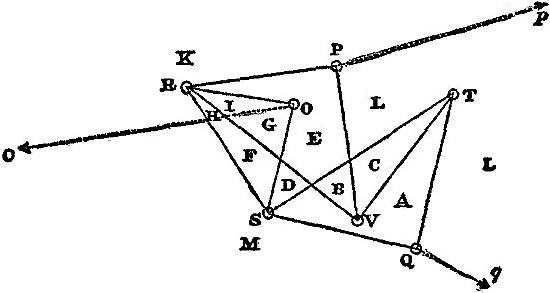
Fig. 1 Diagram of Configuration.
Instead of lettering the joints of the frame, as is usually done, or the links of the frame, as was the custom of Clerk Maxwell, Bow places a letter in each of the polygonal areas enclosed by the links of the frame, and also in each of the divisions of surrounding space as separated by the lines of action of the external forces. When one link of the frame crosses another, the point of apparent intersection of the links is treated as if it were a real joint, and the stresses of each of the intersecting links are represented twice in the diagram of stress, as the opposite sides of the parallelogram which corresponds to the point of intersection.
This method is followed in the lettering of the diagram of configuration (fig. 1), and the diagram of stress (fig. 2) of the linkwork which Professor Sylvester has called a quadruplane.
In fig. 1 the real joints are distinguished from the places where one link appears to cross another by the little circles O, P, Q, R, S, T, V. The four links RSTV form a "contraparallelogram" in which RS = TV and RV = ST. The triangles ROS, RPV, TQS are similar to each other. A fourth triangle (TNV), not drawn in the figure, would complete the quadruplane. The four points O, P, N, Q form a parallelogram whose angle POQ is constant and equal to π - SOR. The product of the distances OP and OQ is constant. The linkwork may be fixed at O. If any figure is traced by P, Q will trace the inverse figure, but turned round O through the constant angle POQ. In the diagram forces Pp, Qq are balanced by the force Co at the fixed point. The forces Pp and Qq are necessarily inversely as OP and OQ, and make equal angles with those lines.
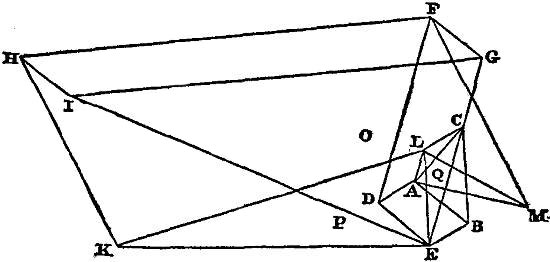
Fig. 2 Diagram of Stress.
Every closed area formed by the links or the external forces in the diagram of configuration is marked by a letter which corresponds to a point of concourse of lines in the diagram of stress. The stress in the link which is the common boundary of two areas is represented in the diagram of stress by the line joining the points corresponding to those areas. When a link is divided into two or more parts by lines crossing it, the stress in each part is represented by a different line for each part, but as the stress is the same throughout the link these lines are all equal and parallel. Thus in the figure the stress in RV is represented by the four equal and parallel lines HI, FG, DE and AB. If two areas have no part of their boundary in common the letters corresponding to them in the diagram of stress are not joined by a straight line. If, however, a straight line were drawn between them, it would represent in direction and magnitude the resultant of all the stresses in the links which are cut by any line, straight or curved, joining the two areas. For instance the areas F and C in fig. 1 have no common boundary, and the points F and C in fig. 2 are not joined by a straight line. But every path from the area F to the area C in fig. 1 passes through a series of other areas, and each passage from one area into a contiguous area corresponds to a line drawn in the diagram of stress. Hence the whole path from F to C in fig. 1 corresponds to a path formed of lines in fig. 2 and extending from F to C, and the resultant of all the stresses in the links cut by the path is represented by FC in fig. 2.
Many examples of stress diagrams are given in the article on bridges (q.v.).
Automatic Description of Diagrams.
There are many other kinds of diagrams in which the two co-ordinates of a point in a plane are employed to indicate the simultaneous values of two related quantities. If a sheet of paper is made to move, say horizontally, with a constant known velocity, while a tracing point is made to move in a vertical straight line, the height varying as the value of any given physical quantity, the point will trace out a curve on the paper from which the value of that quantity at any given time may be determined. This principle is applied to the automatic registration of phenomena of all kinds, from those of meteorology and terrestrial magnetism to the velocity of cannon-shot, the vibrations of sounding bodies, the motions of animals, voluntary and involuntary, and the currents in electric telegraphs.
In Watt's indicator for steam engines the paper does not move with a constant velocity, but its displacement is proportional to that of the piston of the engine, while that of the tracing point is proportional to the pressure of the steam. Hence the co-ordinates of a point of the curve traced on the diagram represent the volume and the pressure of the steam in the cylinder. The indicator-diagram not only supplies a record of the pressure of the steam at each stage of the stroke of the engine, but indicates the work done by the steam in each stroke by the area enclosed by the curve traced on the diagram.(J. C. M.)
DIAL and DIALLING. Dialling, sometimes called gnomonics, is a branch of applied mathematics which treats of the construction of sun-dials, that is, of those instruments, either fixed or portable, which determine the divisions of the day (Lat. dies) by the motion of the shadow of some object on which the sun's rays fall. It must have been one of the earliest applications of a knowledge of the apparent motion of the sun; though for a long time men would probably be satisfied with the division into morning and afternoon as marked by sun-rise, sun-set and the greatest elevation.
History.—The earliest mention of a sun-dial is found in Isaiah xxxviii. 8: "Behold, I will bring again the shadow of the degrees which is gone down in the sun-dial of Ahaz ten degrees backward." The date of this would be about 700 years before the Christian era, but we know nothing of the character or construction of the instrument. The earliest of all sun-dials of which we have any certain knowledge was the hemicycle, or hemisphere, of the Chaldaean astronomer Berossus, who probably lived about 300 B.C. It consisted of a hollow hemisphere placed with its rim perfectly horizontal, and having a bead, or globule, fixed in any way at the centre. So long as the sun remained above the horizon the shadow of the bead would fall on the inside of the hemisphere, and the path of the shadow during the day would be approximately a circular arc. This arc, divided into twelve equal parts, determined twelve equal intervals of time for that day. Now, supposing this were done at the time of the solstices and equinoxes, and on as many intermediate days as might be considered sufficient, and then curve lines drawn through the corresponding points of division of the different arcs, the shadow of the bead falling on one of these curve lines would mark a division of time for that day, and thus we should have a sun-dial which would divide each period of daylight into twelve equal parts. These equal parts were called temporary hours; and, since the duration of daylight varies from day to day, the temporary hours of one day would differ from those of another; but this inequality would probably be disregarded at that time, and especially in countries where the variation between the longest summer day and the shortest winter day is much less than in our climates.
The dial of Berossus remained in use for centuries. The Arabians, as appears from the work of Albategnius, still followed the same construction about the year A.D. 900. Four of these dials have in modern times been found in Italy. One, discovered at Tivoli in 1746, is supposed to have belonged to Cicero, who, in one of his letters, says that he had sent a dial of this kind to his villa near Tusculum. The second and third were found in 1751—one at Castel-Nuovo and the other at Rignano; and a fourth was found in 1762 at Pompeii. G. H. Martini in his Abhandlungen von den Sonnenuhren der Alten (Leipzig, 1777), says that this dial was made for the latitude of Memphis; it may therefore be the work of Egyptians, perhaps constructed in the school of Alexandria.
Herodotus recorded that the Greeks derived from the Babylonians the use of the gnomon, but the great progress made by the Greeks in geometry enabled them in later times to construct dials of great complexity, some of which remain to us, and are proof not only of extensive knowledge but also of great ingenuity.
Ptolemy's Almagest treats of the construction of dials by means of his analemma, an instrument which solved a variety of astronomical problems. The constructions given by him were sufficient for regular dials, that is, horizontal dials, or vertical dials facing east, west, north or south, and these are the only ones he treats of. It is certain, however, that the ancients were able to construct declining dials, as is shown by that most interesting monument of ancient gnomics—the Tower of the Winds at Athens. This is a regular octagon, on the faces of which the eight principal winds are represented, and over them eight different dials—four facing the cardinal points and the other four facing the intermediate directions. The date of the dials is long subsequent to that of the tower; for Vitruvius, who describes the tower in the sixth chapter of his first book, says nothing about the dials, and as he has described all the dials known in his time, we must believe that the dials of the tower did not then exist. The hours are still the temporary hours or, as the Greeks called them, hectemoria.
The first sun-dial erected at Rome was in the year 290 B.C., and this Papirius Cursor had taken from the Samnites. A dial which Valerius Messalla had brought from Catania, the latitude of which is five degrees less than that of Rome, was placed in the forum in the year 261 B.C. The first dial actually constructed at Rome was in the year 164 B.C., by order of Q. Marcius Philippus, but as no other Roman has written on gnomonics, this was perhaps the work of a foreign artist. If, too, we remember that the dial found at Pompeii was made for the latitude of Memphis, and consequently less adapted to its position than that of Catania to Rome, we may infer that mathematical knowledge was not cultivated in Italy.
The Arabians were much more successful. They attached great importance to gnomonics, the principles of which they had learned from the Greeks, but they greatly simplified and diversified the Greek constructions. One of their writers, Abu'l Hassan, who lived about the beginning of the 13th century, taught them how to trace dials on cylindrical, conical and other surfaces. He even introduced equal or equinoctial hours, but the idea was not supported, and the temporary hours alone continued in use.
Where or when the great and important step already conceived by Abu'l Hassan, and perhaps by others, of reckoning by equal hours was generally adopted cannot now be determined. The history of gnomonics from the 13th to the beginning of the 16th century is almost a blank, and during that time the change took place. We can see, however, that the change would necessarily follow the introduction of clocks and other mechanical methods of measuring time; for, however imperfect these were, the hours they marked would be of the same length in summer and in winter, and the discrepancy between these equal hours and the temporary hours of the sun-dial would soon be too important to be overlooked. Now, we know that a balance clock was put up in the palace of Charles V. of France about the year 1370, and we may reasonably suppose that the new sun-dials came into general use during the 14th and 15th centuries.
Among the earliest of the modern writers on gnomonics was Sebastian Münster (q.v.), who published his Horologiographia at Basel in 1531. He gives a number of correct rules, but without demonstrations. Among his inventions was a moon-dial,[1] but this does not admit of much accuracy.
During the 17th century dialling was discussed at great length by many writers on astronomy. Clavius devotes a quarto volume of 800 pages entirely to the subject. This was published in 1612, and may be considered to contain all that was known at that time.
In the 18th century clocks and watches began to supersede sun-dials, and these have gradually fallen into disuse except as an additional ornament to a garden, or in remote country districts where the old dial on the church tower still serves as an occasional check on the modern clock by its side. The art of constructing dials may now be looked upon as little more than a mathematical recreation.
General Principles.—The diurnal and the annual motions of the earth are the elementary astronomical facts on which dialling is founded. That the earth turns upon its axis uniformly from west to east in twenty-four hours, and that it is carried round the sun in one year at a nearly uniform rate, is the correct way of expressing these facts. But the effect will be precisely the same, and it will suit our purpose better, and make our explanations easier, if we adopt the ideas of the ancients, of which our senses furnish apparent confirmation, and assume the earth to be fixed. Then, the sun and stars revolve round the earth's axis uniformly from east to west once a day—the sun lagging a little behind the stars, making its day some four minutes longer—so that at the end of the year it finds itself again in the same place, having made a complete revolution of the heavens relatively to the stars from west to east.
The fixed axis about which all these bodies revolve daily is a line through the earth's centre; but the radius of the earth is so small, compared with the enormous distance of the sun, that, if we draw a parallel axis through any point of the earth's surface, we may safely look on that as being the axis of the celestial motions. The error in the case of the sun would not, at its maximum, that is, at 6 A.M. and 6 P.M., exceed half a second of time, and at noon would vanish. An axis so drawn is in the plane of the meridian, and points to the pole, its elevation being equal to the latitude of the place.
The diurnal motion of the stars is strictly uniform, and so would that of the sun be if the daily retardation of about four minutes, spoken of above, were always the same. But this is constantly altering, so that the time, as measured by the sun's motion, and also consequently as measured by a sun-dial, does not move on at a strictly uniform pace. This irregularity, which is slight, would be of little consequence in the ordinary affairs of life, but clocks and watches being mechanical measures of time could not, except by extreme complication, be made to follow this irregularity, even if desirable.
The clock is constructed to mark uniform time in such wise that the length of the clock day shall be the average of all the solar days in the year. Four times a year the clock and the sun-dial agree exactly; but the sun-dial, now going a little slower, now a little faster, will be sometimes behind, sometimes before the clock-the greatest accumulated difference being about sixteen minutes for a few days in November, but on the average much less. The four days on which the two agree are April 15, June 15, September 1 and December 24.
Clock-time is called mean time, that marked by the sun-dial is called apparent time, and the difference between them is the equation of time. It is given in most calendars and almanacs, frequently under the heading "clock slow," "clock fast." When the time by the sun-dial is known, the equation of time will at once enable us to obtain the corresponding clock-time, or vice versa.
Atmospheric refraction introduces another error by altering the apparent position of the sun; but the effect is too small to need consideration in the construction of an instrument which, with the best workmanship, does not after all admit of very great accuracy.
The general principles of dialling will now be readily understood. The problem before us is the following:—A rod, or style, as it is called, being firmly fixed in a direction parallel to the earth's axis, we have to find how and where points or lines of reference must be traced on some fixed surface behind the style, so that when the shadow of the style falls on a certain one of these lines, we may know that at that moment it is solar noon,—that is, that the plane through the style and through the sun then coincides with the meridian; again, that when the shadow reaches the next line of reference, it is 1 o'clock by solar time, or, which comes to the same thing, that the above plane through the style and through the sun has just turned through the twenty-fourth part of a complete revolution; and so on for the subsequent hours,—the hours before noon being indicated in a similar manner. The style and the surface on which these lines are traced together constitute the dial.
The position of an intended sun-dial having been selected—whether on church tower, south front of farmstead or garden wall—the surface must be prepared, if necessary, to receive the hour-lines.
The chief, and in fact the only practical difficulty will be the accurate fixing of the style, for on its accuracy the value of the instrument depends. It must be in the meridian plane, and must make an angle with the horizon equal to the latitude of the place. The latter condition will offer no difficulty, but the exact determination of the meridian plane which passes through the point where the style is fixed to the surface is not so simple. At present we shall assume that the style has been fixed in its true position. The style itself will be usually a stout metal wire, and when we speak of the shadow cast by the style it must always be understood that the middle line of the thin band of shade is meant.
The point where the style meets the dial is called the centre of the dial. It is the centre from which all the hour-lines radiate.
The position of the XII o'clock line is the most important to determine accurately, since all the others are usually made to depend on this one. We cannot trace it correctly on the dial until the style has been itself accurately fixed in its proper place. When that is done the XII o'clock line will be found by the intersection of the dial surface with the vertical plane which contains the style; and the most simple way of drawing it on the dial will be by suspending a plummet from some point of the style whence it may hang freely, and waiting until the shadows of both style and plumb-line coincide on the dial. This single shadow will be the XII o'clock line.
In one class of dials, namely, all the vertical ones, the XII o'clock line is simply the vertical line from the centre; it can, therefore, at once be traced on the dial face by using a fine plumb-line.
The XII o'clock line being traced, the easiest and most accurate method of tracing the other hour-lines would, at the present day when good watches are common, be by marking where the shadow of the style falls when 1, 2, 3, &c., hours have elapsed since noon, and the next morning by the same means the forenoon hour-lines could be traced; and in the same manner the hours might be subdivided into halves and quarters, or even into minutes.
But formerly, when watches did not exist, the tracing of the I, II, III, &c., o'clock lines was done by calculating the angle which each of these lines would make with the XII o'clock line. Now, except in the simple cases of a horizontal dial or of a vertical dial facing a cardinal point, this would require long and intricate calculations, or elaborate geometrical constructions, implying considerable mathematical knowledge, but also introducing increased chances of error. The chief source of error would lie in the uncertainty of the data; for the position of the dial-plane would have to be found before the calculations began,—that is, it would be necessary to know exactly by how many degrees it declined from the south towards the east or west, and by how many degrees it inclined from the vertical. The ancients, with the means at their disposal, could obtain these results only very roughly.
Dials received different names according to their position:—
Horizontal dials, when traced on a horizontal plane;
Vertical dials, when on a vertical plane facing one of the cardinal points;
Vertical declining dials, on a vertical plane not facing a cardinal point;
Inclining dials, when traced on planes neither vertical nor horizontal (these were further distinguished as reclining when leaning backwards from an observer, proclining when leaning forwards);
Equinoctial dials, when the plane is at right angles to the earth's axis, &c. &c.
Dial Construction.—A very correct view of the problem of dial construction may be obtained as follows:—
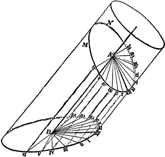
Fig. 1
Conceive a transparent cylinder (fig. 1) having an axis AB parallel to the axis of the earth. On the surface of the cylinder let equidistant generating-lines be traced 15° apart, one of them XII ... XII being in the meridian plane through AB, and the others I ... I, II ... II, &c., following in the order of the sun's motion.
Then the shadow of the line AB will obviously fall on the line XII ... XII at apparent noon, on the line I ... I at one hour after noon, on II ... II at two hours after noon, and so on. If now the cylinder be cut by any plane MN representing the plane on which the dial is to be traced, the shadow of AB will be intercepted by this plane and fall on the lines AXII AI, AII, &c.
The construction of the dial consists in determining the angles made by AI, AII, &c. with AXII; the line AXII itself, being in the vertical plane through AB, may be supposed known.
For the purposes of actual calculation, perhaps a transparent sphere will, with advantage, replace the cylinder, and we shall here apply it to calculate the angles made by the hour-line with the XII o'clock line in the two cases of a horizontal dial and of a vertical south dial.
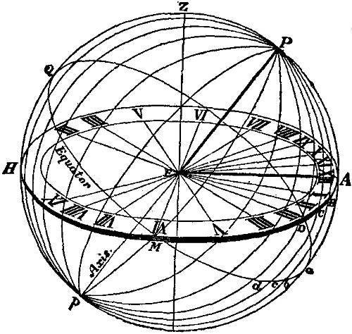
Fig. 2.
Horizontal Dial.—Let PEp (fig. 2), the axis of the supposed transparent sphere, be directed towards the north and south poles of the heavens. Draw the two great circles, HMA, QMa, the former
horizontal, the other perpendicular to the axis Pp, and therefore coinciding with the plane of the equator. Let EZ be vertical, then the circle QZP will be the meridian, and by its intersection A with the horizontal circle will determine the XII o'clock line EA. Next divide the equatorial circle QMa into 24 equal parts ab, bc, cd, &c. ... of 15° each, beginning from the meridian Pa, and through the various points of division and the poles draw the great circles Pbp, Pcp, &c. ... These will exactly correspond to the equidistant generating lines on the cylinder in the previous construction, and the shadow of the style will fall on these circles after successive intervals of 1,2, 3, &c., hours from noon. If they meet the horizontal circle in the points B, C, D, &c., then EB, EC, ED, &c. ... will be the I, II, III, &c., hour-lines required; and the problem of the horizontal dial consists in calculating the angles which these lines make with the XII o'clock line EA, whose position is known. The spherical triangles PAB, PAC, &c., enable us to do this readily. They are all right-angled at A, the side PA is the latitude of the place, and the angles APB, APC, &c., are respectively 15°, 30°, &c., then
tan AB = tan 15° sin latitude, tan AC = tan 30° sin latitude, &c. &c.
These determine the sides AB, AC, &c., that is, the angles AEB, AEC, &c., required.
The I o'clock hour-line EB must make an angle with the meridian EA of 11° 51' on a London dial, of 12° 31' at Edinburgh, of 11° 23' at Paris, 12° 0' at Berlin, 9° 55' at New York and 9° 19' at San Francisco. In the same way may be found the angles made by the other hour-lines.
The calculations of these angles must extend throughout one quadrant from noon to VI o'clock, but need not be carried further, because all the other hour-lines can at once be deduced from these. In the first place the dial is symmetrically divided by the meridian, and therefore two times equidistant from noon will have their hour-lines equidistant from the meridian; thus the XI o'clock line and the I o'clock line must make the same angles with it, the X o'clock the same as the II o'clock, and so on. And next, the 24 great circles, which were drawn to determine these lines, are in reality only 12; for clearly the great circle which gives I o'clock after midnight, and that which gives I o'clock after noon, are one and the same, and so also for the other hours. Therefore the hour-lines between VI in the evening and VI the next morning are the prolongations of the remaining twelve.
Let us now remove the imaginary sphere with all its circles, and retain only the style EP and the plane HMA with the lines traced on it, and we shall have the horizontal dial.
On the longest day in London the sun rises a little before 4 o'clock, and sets a little after 8 o'clock; there is therefore no necessity for extending a London dial beyond those hours. At Edinburgh the limits will be a little longer, while at Hammerfest, which is within the Arctic circle, the whole circuit will be required.
Instead of a wire style it is often more convenient to use a metal plate from one quarter to half an inch in thickness. This plate, which is sometimes in the form of a right-angled triangle, must have an acute angle equal to the latitude of the place, and, when properly fixed in a vertical position on the dial, its two faces must coincide with the meridian plane, and the sloping edges formed by the thickness of the plate must point to the pole and form two parallel styles. Since there are two styles, there must be two dials, or rather two half dials, because a little consideration will show that, owing to the thickness of the plate, these styles will only one at a time cast a shadow. Thus the eastern edge will give the shadow for all hours before 6 o'clock in the morning. From 6 o'clock until noon the western edge will be used. At noon it will change again to the eastern edge until 6 o'clock in the evening, and finally the western edge for the remaining hours of daylight.
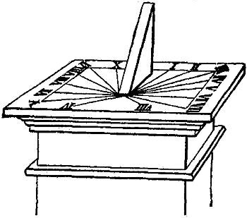
Fig. 3.
The centres of the two dials will be at the points where the styles meet the dial face; but, in drawing the hour-lines, we must be careful to draw only those lines for which the corresponding style is able to give a shadow as explained above. The dial will thus have the appearance of a single dial plate, and there will be no confusion (see fig. 3).
The line of demarcation between the shadow and the light will be better defined than when a wire style is used; but the indications by this double dial will always be one minute too fast in the morning and one minute too slow in the afternoon. This is owing to the magnitude of the sun, whose angular breadth is half a degree. The well-defined shadows are given, not by the centre of the sun, as we should require them, but by the forward limb in the morning and by the backward one in the afternoon; and the sun takes just about a minute to advance through a space equal to its half-breadth.
Dials of this description are frequently met with. The dial plate is of metal as well as the vertical piece upon it, and they may be purchased ready for placing on the pedestal,—the dial with all the hour-lines traced on it and the style plate firmly fastened in its proper position, if not even cast in the same piece with the dial plate.
When placing it on the pedestal care must be taken that the dial be perfectly horizontal and accurately oriented. The levelling will be done with a spirit-level, and the orientation will be best effected either in the forenoon or in the afternoon, by turning the dial plate till the time given by the shadow (making the one minute correction mentioned above) agrees with a good watch whose error on solar time is known. It is, however, important to bear in mind that a dial, so built up beforehand, will have the angle at the base equal to the latitude of some selected place, such as London, and the hour-lines will be drawn in directions calculated for the same latitude. Such a dial can therefore not be used near Edinburgh or Glasgow, although it would, without appreciable error, be adapted to any place whose latitude did not differ more than 20 or 30 m. from that of London, and it would be safe to employ it in Essex, Kent or Wiltshire.
If a series of such dials were constructed, differing by 30 m. in latitude, then an intending purchaser could select one adapted to a place whose latitude was within 15 m. of his own, and the error of time would never exceed a small fraction of a minute. The following table will enable us to check the accuracy of the hour-lines and of the angle of the style,—all angles on the dial being readily measured with an ordinary protractor. It extends from 50° lat. to 59½° lat., and therefore includes the whole of Great Britain and Ireland:—
LAT. XI. A.M. I. P.M. X. A.M. II. P.M. IX. A.M. III. P.M. VIII. A.M. IIII. P.M. VII. A.M. V. P.M. VI. A.M. VI. P.M.
50°0′ 11°36′ 23°51′ 37°27′ 53°0′ 70°43′ 90°0′
5030 1141 241 3739 5312 7051 900
510 1146 2410 3751 5323 7059 900
5130 1151 2419 383 5335 716 900
520 1155 2428 3814 5346 7113 900
5230 120 2437 3825 5357 7120 900
530 125 2445 3837 548 7127 900
5330 129 2454 3848 5419 7134 900
540 1214 252 3858 5429 7140 900
5430 1218 2510 399 5439 7147 900
550 1223 2519 3919 5449 7153 900
5530 1227 2527 3930 5459 7159 900
560 1231 2535 3940 559 725 900
5630 1236 2543 3950 5518 7211 900
570 1240 2550 3959 5527 7217 900
5730 1244 2558 409 5536 7222 900
580 1248 265 4018 5545 7228 900
5830 1252 2613 4027 5554 7233 900
590 1256 2620 4036 562 7239 900
5930 130 2627 4045 5611 7244 900
Vertical South Dial.—Let us take again our imaginary transparent sphere QZPA (fig. 4), whose axis PEp is parallel to the earth's axis. Let Z be the zenith, and, consequently, the great circle QZP the meridian. Through E, the centre of the sphere, draw a vertical plane facing south. This will cut the sphere in the great circle ZMA, which, being vertical, will pass through the zenith, and, facing south, will be at right angles to the meridian. Let QMa be the equatorial circle, obtained by drawing a plane through E at right angles to the axis PEp. The lower portion Ep of the axis will be the style, the vertical line EA in the meridian plane will be the XII o'clock line, and the line EM, which is obviously horizontal, since M is the intersection of two great circles ZM, QM, each at right angles to the vertical plane QZP, will be the VI o'clock line. Now, as in the previous problem, divide the equatorial circle into 24 equal arcs of 15° each, beginning at a, viz. ab, bc, &c.,—each quadrant aM, MQ, &c., containing 6,—then through each point of division and through the axis Pp draw a plane cutting the sphere in 24 equidistant great circles. As the sun revolves round the axis the shadow of the axis will successively fall on these circles at intervals of one hour, and if these circles cross the vertical circle ZMA in the points A, B, C, &c., the shadow of the lower portion Ep of the axis will fall on the lines EA, EB, EC, &c., which will therefore be the required hour-lines on the vertical dial, Ep being the style.
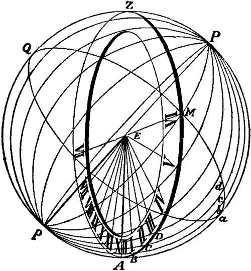
Fig. 4.
There is no necessity for going beyond the VI o'clock hour-line on each side of noon; for, in the winter months the sun sets earlier than 6 o'clock, and in the summer months it passes behind the plane of the dial before that time, and is no longer available.
It remains to show how the angles AEB, AEC, &c., may be calculated.
The spherical triangles pAB, pAC, &c., will give us a simple rule. These triangles are all right-angled at A, the side pA, equal to ZP, is the co-latitude of the place, that is, the difference between the latitude and 90°; and the successive angles ApB, ApC, &c., are 15°, 30°, &c., respectively. Then
tan AB = tan 15° sin co-latitude;
or more simply,
tan AB = tan 15° cos latitude, tan AC = tan 30° cos latitude, &c. &c.
and the arcs AB, AC so found are the measure of the angles AEB, AEC, &c., required.
In this ease the angles diminish as the latitudes increase, the opposite result to that of the horizontal dial.
Inclining, Reclining, &c., Dials.—We shall not enter into the calculation of these cases. Our imaginary sphere being, as before supposed, constructed with its centre at the centre of the dial, and all the hour-circles traced upon it, the intersection of these hour-circles with the plane of the dial will determine the hour-lines just as in the previous cases; but the triangles will no longer be right-angled, and the simplicity of the calculation will be lost, the chances of error being greatly increased by the difficulty of drawing the dial plane in its true position on the sphere, since that true position will have to be found from observations which can be only roughly performed.
In all these cases, and in cases where the dial surface is not a plane, and the hour-lines, consequently, are not straight lines, the only safe practical way is to mark rapidly on the dial a few points (one is sufficient when the dial face is plane) of the shadow at the moment when a good watch shows that the hour has arrived, and afterwards connect these points with the centre by a continuous line. Of course the style must have been accurately fixed in its true position before we begin.
Equatorial Dial.—The name equatorial dial is given to one whose plane is at right angles to the style, and therefore parallel to the equator. It is the simplest of all dials. A circle (fig. 5) divided into 24 equal ares is placed at right angles to the style, and hour divisions are marked upon it. Then if care be taken that the style point accurately to the pole, and that the noon division coincide with the meridian plane, the shadow of the style will fall on the other divisions, each at its proper time. The divisions must be marked on both sides of the dial, because the sun will shine on opposite sides in the summer and in the winter months, changing at each equinox.