Chapter III · - HOW TO GO TO WORK TO LAY OUT A SYSTEM OF DRAINS. (continued 2)
Reading edition
Main Drains.—The valley through which the brook now runs is about 80 feet wide, with a decided rise in the land at each side. If one main drain were laid in the center of it, all of the laterals coming to the main would first run down a steep hillside, and then across a stretch of more level land, requiring the grade of each lateral to be broken at the foot of the hill, and provided with a silt basin to collect matters which might be deposited when the fall becomes less rapid. Consequently, it is best to provide two mains, or collecting drains, (A and C,) one lying at the foot of each hill, when they will receive the[pg 097] laterals at their greatest fall; but, as these are too far apart to completely drain the valley between them, and are located on land higher than the center of the valley, a drain, (B,) should be run up, midway between them.
The collecting drain, A, will receive the laterals from the hill to the west of it, as far up as the 10-foot contour line, and, above that point,—running up a branch of the valley,—it will receive laterals from both sides. The drain, B, may be continued above the dividing point of the valley, and will act as one of the series of laterals. The drain, C, will receive the laterals and sub-mains from the rising ground to the east of it, and from both sides of the minor valley which extends in that direction.
Most of the valley which runs up from the easterly side of the swamp must be drained independently by the drain E, which might be carried to the silt basin, did not its continuation directly to the outlet offer a shorter course for the removal of its water. This drain will receive laterals from the hill bordering the southeasterly side of the swamp, and, higher up, from both sides of the valley in which it runs.
In laying out these main drains, more attention should be given to placing them where they will best receive the water of the laterals, and on lines which offer a good and tolerably uniform descent, than to their use for the immediate drainage of the land through which they pass. Afterward, in laying out the laterals, the use of these lines as local drains should, of course, be duly considered.
The Lateral Drains should next receive attention, and in their location and arrangement the following rules should be observed:
1st. They should run down the steepest descent of the land.
2d. They should be placed at intervals proportionate to their depth;—if 4 feet deep, at 40 feet intervals; if 3 feet deep, at 20 feet intervals.
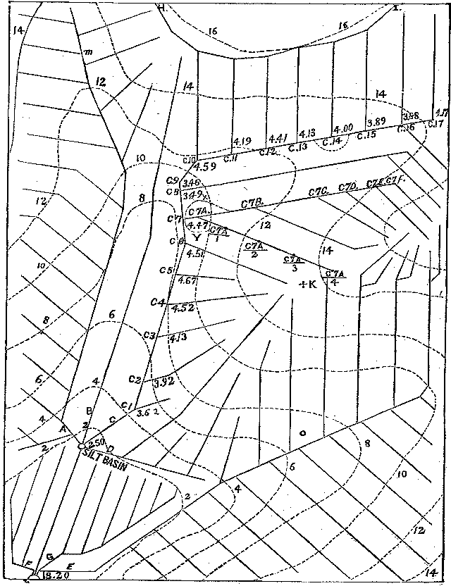
Fig. 20 - MAP WITH DRAINS AND CONTOUR LINES.
[pg 099]
3d. They should, as nearly as possible, run parallel to each other.
On land of perfectly uniform character, (all sloping in the same direction,) all of these requirements may be complied with, but on irregular land it becomes constantly necessary to make a compromise between them. Drains running down the line of steepest descent cannot be parallel,—and, consequently, the intervals between them cannot be always the same; those which are farther apart at one end than at the other cannot be always of a depth exactly proportionate to their intervals.
In the adjustment of the lines, so as to conform as nearly to these requirements as the shape of the ground will allow, there is room for the exercise of much skill, and on such adjustment depend, in a great degree, the success and economy of the work. Remembering that on the map, the line of steepest descent is exactly perpendicular to the contour lines of the land, it will be profitable to study carefully the system of drains first laid out, erasing and making alterations wherever it is found possible to simplify the arrangement.
Strictly speaking, all angles are, to a certain extent, wasteful, because, if two parallel drains will suffice to drain the land between them, no better drainage will be effected by a third drain running across that land. Furthermore, the angles are practically supplied with drains at less intervals than are required,—for instance, at C 7 a on the map the triangles included within the dotted line x, y, will be doubly drained. So, also, if any point of a 4-foot drain will drain the land within 20 feet of it, the land included within the dotted line forming a semi-circle about the point C 14, might drain into the end of the lateral, and it no more needs the action of the main drain than does that which lies between the laterals. Of course, angles and connecting lines are indispensable, except where the laterals can run independently[pg 100] across the entire field, and discharge beyond it. The longer the laterals can be made, and the more angles can be avoided, the more economical will the arrangement be; and, until the arrangement of the lines has been made as nearly perfect as possible, the time of the drainer can be in no way so profitably spent as in amending his plan.
The series of laterals which discharge through the mains A, C, D and E, on the accompanying map, have been very carefully considered, and are submitted to the consideration of the reader, in illustration of what has been said above.
At one point, just above the middle of the east side of the field, the laterals are placed at a general distance of 20 feet, because, as will be seen by reference to Fig. 4, a ledge of rock, underground, will prevent their being made more than 3 feet deep.
The line from H to I, (Fig. 20,) at the north side of the field, connecting the heads of the laterals, is to be a stone and tile drain, such as is described on page 60, intended to collect the water which follows the surface of the rock. (See Fig. 4.)
The swamp is to be drained by itself, by means of two series of laterals discharging into the main lines F and G, which discharge at the outlet, by the side of the main drain from the silt-basin. By this arrangement, these laterals, especially at the north side of the swamp, being accurately laid, with very slight inclinations, can be placed more deeply than if they ran in an east and west direction, and discharged into the main, which has a greater inclination, and is only two and a half feet deep at the basin. Being 3-1/2 (3.50) feet deep at the outlet, they may be made fully 3 feet deep at their upper ends, and, being only 20 feet apart, they will drain the land as well as is possible. The drains being now laid out, over the whole field, the next thing to be attended to is
[pg 101]
The Ordering of the Tile.—The main line from the outlet up to the silt-basin, should be of 3-1/2-inch tiles, of which about 190 feet will be required. The main drain A should be laid with 2-1/4-inch tiles to the point marked m, near its upper end, as the lateral entering there carries the water of a spring, which is supposed to fill a 1-1/4-inch tile. The length of this drain, from the silt-basin to that point is 575 feet. The main drain C will require 2-1/4 inch tiles from the silt-basin to the junction with the lateral, which is marked C 10, above which point there is about 1,700 feet of drain discharging into it, a portion of which, being a stone-and-tile drain at the foot of a rock, may be supposed to receive more water than that which lies under the rest of the land;—distance 450 feet. The main drain E requires 2-1/4-inch tiles from the outlet to the point marked o, a distance of 380 feet. This tile will, in addition to its other work, carry as much water from the spring, on the line of its fourth lateral, as would fill a 1-1/4-inch pipe.12
The length of the main drains above the points indicated, and of all the laterals, amounts to about 12,250 feet. These all require 1-1/4-inch tiles.
Allowing about five per cent. for breakage, the order in round numbers, will be as follows:13
3-1/2-inch round tiles 200 feet.
2-1/4-inch round tiles 1,500 feet.
1-1/4-inch round tiles 13,000 feet.
3-1/2-inch round tiles 1,600
2-1/4-inch round tiles 13,250
[pg 102]
Order, also, 25 6-inch sole-tiles, to be used in making small silt-basins.
It should be arranged to have the tiles all on the ground before the work of ditching commences, so that there may be no delay and consequent danger to the stability of the banks of the ditches, while waiting for them to arrive. As has been before stated, it should be especially agreed with the tile-maker, at the time of making the contract, that every tile should be perfect;—of uniform shape, and neither too much nor too little burned.
Staking Out.—Due consideration having been given to such preliminaries as are connected with the mapping of the ground, and the arrangement, on paper, of the drains to be made, the drainer may now return to his field, and, while awaiting the arrival of his tiles, make the necessary preparation for the work to be done. The first step is to fix certain prominent points, which will serve to connect the map with the field, by actual measurements, and this will very easily be done by the aid of the stakes which are still standing at the intersections of the 50-foot lines, which were used in the preliminary levelling.
Commencing at the southwest corner of the field, and measuring toward the east a distance of 34 feet, set a pole to indicate the position of the outlet. Next, mark the center of the silt-basin at the proper point, which will be found by measuring 184 feet up the western boundary, and thence toward the east 96 feet, on a line parallel with the nearest row of 50-foot stakes. Then, in like manner, fix the points C1, C6, C9, C10, and C17, and the angles of the other main lines, marking the stakes, when placed, to correspond with the same points on the map. Then stake the angles and the upper ends of the laterals, and mark these stakes to correspond with the map.
It will greatly facilitate this operation, if the plan of the drains which is used in the field, from which the horizontal[pg 103] lines should be omitted, have the intersecting 50-foot lines drawn upon it, so that the measurements may be made from the nearest points of intersection.14
Having staked these guiding points of the drains, it is advisable to remove all of the 50-foot stakes, as these are of no further use, and would only cause confusion. It will now be easy to set the remaining stakes,—placing one at every 50 feet of the laterals, and at the intersections of all the lines.
A system for marking the stakes is indicated on the map, (in the C series of drains,) which, to avoid the confusion which would result from too much detail on such a small scale, has been carried only to the extent necessary for illustration. The stakes of the line C are marked C1, C2, C3, etc. The stakes of the sub-main C7, are marked C7a, C7b, C7c, etc. The stakes of the lateral which enters this drain at C7a, are marked C7a/1, C7a/2, C7a/3, etc. etc. This system, which connects the lettering of each lateral with its own sub-main and main, is perfectly simple, and avoids the possibility of confusion. The position of the stakes should all be lettered on the map, at the original drawing, and the same designating marks put on the stakes in the field, as soon as set.
Grade Stakes, (pegs about 8 or 10 inches long,) should be placed close at the sides of the marked stakes, and driven nearly their full length into the ground. The tops of these stakes furnish fixed points of elevation from which to take the measurements, and to make the computations necessary to fix the depth of the drain at each stake. If the measurements were taken from the surface of the ground, a slight change of position in placing the instrument, would often make a difference of some inches in the depth of the drain.
[pg 104]
Taking the Levels.—For accurate work, it is necessary to ascertain the comparative levels of the tops of all of the grade stakes; or the distance of each one of them below an imaginary horizontal plane. This plane, (in which we use only such lines as are directly above the drains,) may be called the "Datum Line." Its elevation should be such that it will be above the highest part of the land, and, for convenience, it is fixed at the elevation of the levelling instrument when it is so placed as to look over the highest part of the field.
Levelling Instruments are of various kinds. The best for the work in hand, is the common railroad level, which is shown in Fig. 6. This is supported on three legs, which bring it to about the level of the eye. Its essential parts are a telescope, which has two cross-hairs intersecting each other in the line of sight, and which may be turned on its pivot toward any point of the horizon; a bubble glass placed exactly parallel to the line of sight, and firmly secured in its position so as to turn with the telescope; and an apparatus for raising or depressing any side of the instrument by means of set-screws. The instrument is firmly screwed to the tripod, and placed at a point convenient for looking over a considerable part of the highest land. By the use of the set-screws, the plane in which the instrument revolves is brought to a level, so that in whatever direction the instrument is pointed, the bubble will be in the center of the glass. The line of sight, whichever way it is turned, is now in our imaginary plane. A convenient position for the instrument in the field under consideration, would be at the point, east of the center, marked K, which is about 3 feet below the level of the highest part of the ground. The telescope should stand about 5 feet above the surface of the ground directly under it.
The Levelling-Rod, (See Fig. 7,) is usually 12 feet long, is divided into feet and hundredths of a foot, and has a[pg 105] movable target which may be placed at any part of its entire length. This is carried by an attendant, who holds it perpendicularly on the top of the grade-stake, while the operator, looking through the telescope, directs him to move the target up and down until its center is exactly in the line of sight. The attendant then reads the elevation, and the operator records it as the distance below the datum-line of the top of the grade-stake. For convenience, the letterings of the stakes should be systematically entered in a small field book, before the work commences, and this should be accompanied by such a sketch of the plan as will serve as a guide to the location of the lines on the ground.
The following is the form of the field book for the main drain C, with the levels recorded:
Lettering of the Stake.Depth from Datum Line.
Silt Basin18.20
C 115.44
C 214.36
C 312.85
C 412.18
C 511.79
C 611.69
C 711.55
C 811.37
C 911.06
C 108.94
C 118.52
C 127.86
C 137.70
C 147.39
C 157.06
C 166.73
The levelling should be continued in this manner, until the grades of all the points are recorded in the field book.
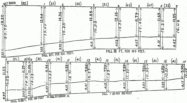
Fig. 21 - PROFILE OF DRAIN C.
Horizontal Scale, 66 ft. to the inch. Vertical Scale, 15 ft. to the inch. 1 to 17. Numbers of Stakes. (82) etc. Distances between Stakes. 18.20 etc. Depths from datum-line to surface. 2.50 etc. Depths of ditch. 20.70 etc. Depths from datum-line to drain.
If, from too great depression of the lower parts of the field, or too great distances for observation, it becomes necessary to take up a new position with the instrument, the new level should be connected, by measurement, with[pg 107] the old one, and the new observations should be computed to the original plane.
It is not necessary that these levels should be noted on the map,—they are needed only for computing the depth of cutting, and if entered on the map, might be mistaken for the figures indicating the depth, which it is more important to have recorded in their proper positions, for convenience of reference during the work.
The Depth and Grade of the Drains.—Having now staked out the lines upon the land, and ascertained and recorded the elevations at the different stakes, it becomes necessary to determine at what depth the tile shall be placed at each point, so as to give the proper fall to each line, and to bring all of the lines of the system into accord. As the simplest means of illustrating the principle on which this work should be done, it will be convenient to go through with the process with reference to the main drain C, of the plan under consideration. A profile of this line is shown in Fig. 21, where the line is broken at stake No. 7, and continued in the lower section of the diagram. The topmost line, from "Silt Basin" to "17," is the horizontal datum-line. The numbers above the vertical lines indicate the stakes; the figures in brackets between these, the number of feet between the stakes; and the heavy figures at the left of the vertical lines, the recorded measurements of depth from the datum-line to the surface of the ground, which is indicated by the irregular line next below the datum-line. The vertical measurements are, of course, very much exaggerated, to make the profile more marked, but they are in the proper relation to each other.
The depth at the silt-basin is fixed at 2-1/2 feet (2.50.) The rise is rapid to stake 3, very slight from there to stake 7, very rapid from there to stake 10, a little less rapid from there to stake 11, and still less rapid from there to stake 17.
To establish the grade by the profile alone, the proper[pg 108] course would be to fix the depth at the stakes at which the inclination is to be changed, to draw straight lines between the points thus found, and then to measure the vertical distance from these lines to the line indicating the surface of the ground at the different stakes; thus, fixing the depth at stake 3, at 4 feet and 13 hundredths,15 the line drawn from that point to the depth of 2.50, at the silt-basin, will be 3 feet and 62 hundredths (3.62) below stake 1, and 3 feet and 92 hundredths (3.92) below stake 2. At stake 7 it is necessary to go sufficiently deep to pass from 7 to 10, without coming too near the surface at 9, which is at the foot of a steep ascent. A line drawn straight from 4.59 feet below stake 10 to 4.17 feet at stake 17, would be unnecessarily deep at 11, 12, 13, and 14; and, consequently it is better to rise to 4.19 feet at 11. So far as this part of the drain is concerned, it would be well to continue the same rise to 12, but, in doing so, we would come too near the surface at 13, 14, and 15; or must considerably depress the line at 16, which would either make a bad break in the fall at that point, or carry the drain too deep at 17.
By the arrangement adopted, the grade is broken at 3, 7, 10, and 11. Between these points, it is a straight line, with the rate of fall indicated in the following table, which commences at the upper end of the drain and proceeds toward its outlet:
From Stake, Depth.To Stake, Depth.Distance.Total Fall.Rate of Fall. Per 100 Ft.
No. 17...4.17 ft.No. 11...4.19 ft.246 ft.2.46 ft.1.09 ft.
No. 11...4.19 ft.No. 10...4.59 ft.41 ft.82 ft.2.00 ft.
No. 10...4.59 ft.No. 7...4.47 ft.91 ft.2.49 ft.2.83 ft.
No. 7...4.47 ft.No. 3...4.13 ft.173 ft.96 ft.56 ft.
No. 3...4.13 ft.S. Basin 2.25 ft.186 ft.3.47 ft.1.87 ft.
It will be seen that the fall becomes more rapid as we ascend from stake 7, but below this point it is very much[pg 109] reduced, so much as to make it very likely that silt will be deposited, (see page 91), and the drain, thereby, obstructed. To provide against this, a silt-basin must be placed at this point which will collect the silt and prevent its entrance into the more nearly level tile below. The construction of this silt-basin is more particularly described in the next chapter. From stake 7 to the main silt-basin the fall is such that the drain will clear itself.
The drawing of regular profiles, for the more important drains, will be useful for the purpose of making the beginner familiar with the method of grading, and with the principles on which the grade and depth are computed; and sometimes, in passing over very irregular surfaces, this method will enable even a skilled drainer to hit upon the best adjustment in less time than by computation. Ordinarily, however, the form of computation given in the following table, which refers to the same drain, (C,) will be more expeditious, and its results are mathematically more correct.16
Fall. Feet and Decimals.Depth from Datum Line.
No. of Stake.Distance Between Stakes.Per 100 Feet.Between Stakes.To Drain.To Surface.Depth of Drain.Remarks.
Silt Basin.20.70 ft.18.20 ft.2.50 ft
C. 1. 82 ft. 2 ft.1.64 ft.19.06 "15.44 "3.48 ft
C. 2. 39 ft.do. .78 ft. 18.28 "14.36 "3.83 ft
C. 3. 65 ft.do. 1.30 ft. 16.98 "12.85 "4.13 ft
C. 4. 51 ft..56 .28 ft. 16.70 "12.18 "4.52 ft
C. 5. 43 ft.do. .24 ft. 16.46 "11.79 "4.67 ft
C. 6. 47 ft.do. .26 ft. 16.20 "11.69 "4.51 ft
C. 7. 32 ft.do. .18 ft. 16.02 "11.55 "4.47 ft Silt-Basin here. Made deep at Nos. 7 and 10 to pass a depression of the surface at No. 9.
C. 8. 41 ft. 2.83 1.16 ft. 14.86 "11.37 "3.49 ft
C. 9. 12 ft.do. .34 ft. 14.52 "11.06 "3.46 ft
C.10. 38 ft.do. .99 ft. 13.53 " 8.94 "4.59 ft
C.11. 41 ft. 2.00 .82 ft. 12.61 " 8.52 "4.19 ft
C.12. 41 ft. 1.09 .44 ft. 12.27 " 7.86 "4.41 ft
C.13. 41 ft.do. .44 ft. 11.83 " 7.70 "4.13 ft
C.14. 41 ft.do. .44 ft. 11.39 " 7.39 "4.00 ft
C.15. 41 ft.do. .44 ft. 10.95 " 7.06 "3.89 ft
C.16. 41 ft.do. .44 ft. 10.51 " 6.73 "3.88 ft
C.17. 41 ft.do. .44 ft. 10.07 " 5.90 "4.17 ft
[pg 110]
Note.—The method of making the foregoing computation is this:
1st. Enter the lettering of the stakes in the first column, commencing at the lower end of the drain.
2d. Enter the distances between each two stakes in the second column, placing the measurement on the line with the number of the upper stake of the two.
3d. In the next to the last column enter, on the line with each stake, its depth below the datum-line, as recorded in the field book of levels, (See page 105.)
4th. On the first line of the last column, place the depth of the lower end of the drain, (this is established by the grade of the main or other outlet at which it discharges.)
5th. Add this depth to the first number of the line next preceding it, and enter the sum obtained on the first line of the fifth column, as the depth of the drain below the datum-line.
6th. Having reference to the grade of the surface, (as shown by the figures in the sixth column,) as well as to any necessity for placing the drain at certain depths at certain places, enter the desired depth, in pencil, in the last column, opposite the stakes marking those places. Then add together this depth and the corresponding surface measurement in the column next preceding, and enter the sum, in pencil, in the fifth column, as the depth from the datum-line to the desired position of the drain. (In the example in hand, these points are at Nos. 3, 7, 10, 11, and 17.)
7th. Subtract the second amount in the fifth column from the first amount for the total fall between the two points—in the example, "3" from "Silt-Basin." Divide this total fall, (in feet and hundredths,) by one hundredth of the total number of feet between them. The result will be the rate of fall per 100 feet, and this should be entered, in the third column, opposite each of the intermediate distances between the points.
Example:
Depth of the Drain at the Silt-Basin20.45 feet.
Depth of the Drain at the Stake No. 316.98 feet.
——
Difference3.47 feet.
Distance between the two186.— feet.
1.86)3.47(1.865 or 1.87
1 86 —— 1 610 1 488 —— 1 220 1 116 —— 1 040 930 —— 110
[pg 111]
8th. Multiply the numbers of the second column by those of the third and divide the product by 100. The result will be the amount of fall between the stakes, (fourth column.)—Example: 1.87×82=153÷100=1.53.
9th. Subtract the first number of the fourth column from the first number of the fifth column, (on the line above it,) and place the remainder on the next line of the fifth column.—Example: 20.70-1.64= 19.06.
Then, from this new amount, subtract the second number of the fourth column, for the next number of the fifth, and so on, until, in place of the entry in pencil, (Stake 3,) we place the exact result of the computation.
Proceed in like manner with the next interval,—3 to 7.
10th. Subtract the numbers in the sixth column from those in the fifth, and the remainders will be the depths to be entered in the last.
Under the head of "Remarks," note any peculiarity of the drain which may require attention in the field.
The main lines A, D, and E, and the drain B, should next be graded on the plan set forth for C, and their laterals, all of which have considerable fall, and being all so steep as not to require silt-basins at any point,—can, by a very simple application of the foregoing principles, be adjusted at the proper depths. In grading the stone and tile drain, (H, I,) it is only necessary to adopt the depth of the last stakes of the laterals, with which it is connected, as it is immaterial in which direction the water flows. The ends of this drain,—from H to the head of the drain C10, and from I to the head of C17,—should, of course, have a decided fall toward the drains.
The laterals which are placed at intervals of 20 feet, over the underground rock on the east side of the field, should be continued at a depth of about 3 feet for nearly their whole length, dropping in a distance of 8 or 10 feet at their lower ends to the top of the tile of the main. The intervals between the lower ends of C7c, C7d, and C7e, being considerably more than 20 feet, the drains may be gradually deepened, throughout their whole length from 3 feet at the upper ends to the depth of the top of the main at the lower ends.
The main drains F and G, being laid in flat land, their[pg 112] outlets being fixed at a depth of 3.50, (the floor of the main outlet,) and it being necessary to have them as deep as possible throughout their entire length, should be graded with great care on the least admissible fall. This, in ordinary agricultural drainage, may be fixed at .25, or 3 inches, per 100 feet. Their laterals should commence with the top of their 1/4 tile even with the top of the 2-1/2 collar of the main,—or .15 higher than the grade of the main,—and rise, at a uniform inclination of .25, to the upper end.
Having now computed the depth at which the tile is to lie, at each stake, and entered it on the map, we are ready to mark these depths on their respective stakes in the field, when the preliminary engineering of the work will be completed.
It has been deemed advisable in this chapter to consider the smallest details of the work of the draining engineer. Those who intend to drain in the best manner will find such details important. Those who propose to do their work less thoroughly, may still be guided by the principles on which they are based. Any person who will take the pains to mature the plans of his work as closely as has been here recommended, will as a consequence commence his operations in the field much more understandingly. The advantage of having everything decided beforehand,—so that the workmen need not be delayed for want of sufficient directions, and of making, on the map, such alterations as would have appeared necessary in the field, thus saving the cost of cutting ditches in the wrong places, will well repay the work of the evenings of a whole winter.
[pg 113]