Volume 2 — CHAPTER XL TELEPHONE TRAIN DISPATCHING[A]
Reading edition
CHAPTER XL TELEPHONE TRAIN DISPATCHING[A]
It has been only within the past three few that the telephone has begun to replace the telegraph for handling train movements. The telegraph and the railroads have grown up together in this country since 1850, and in view of the excellent results that the telegraph has given in train dispatching and of the close alliance that has always naturally existed between the railway and the telegraph, it has been difficult for the telephone, which came much later, to enter the field.
Rapid Growth. The telephone has been in general use among the railroads for many years, but only on a few short lines has it been used for dispatching trains. In these cases the ordinary magneto circuit and instruments have been employed, differing in no respect from those used in commercial service at the present time. Code ringing was used and the number of stations on a circuit was limited by the same causes that limit the telephones on commercial party lines at present.
The present type of telephone dispatching systems, however, differs essentially from the systems used in commercial work, and is, in fact, a highly specialized party-line system, arranged for selective ringing and many stations. The first of the present type was installed by the New York Central and Hudson River Railroad in October, 1907, between Albany and Fonda, New York, a distance of 40 miles. This section of the road is on the main line and has four tracks controlled by block signals.
The Chicago, Burlington, and Quincy Railroad was the second to install train-dispatching circuits. In December, 1907, a portion of the main line from Aurora to Mendota, Illinois, a distance of 46 miles, was equipped. This was followed in quick succession by various other circuits ranging, in general, in lengths over 100 miles. At the present time there are over 20 train-dispatching circuits on the Chicago, Burlington, and Quincy Railroad covering 125 miles of double track, 28 miles of multi-track, and 1,381 miles of single track, and connecting with 286 stations.
Other railroads entered this field in quick order after the initial installations, and at the present time nearly every large railroad system in the United States is equipped with several telephone train-dispatching circuits and all of these seem to be extending their systems.
In 1910, several railroads, including the Delaware, Lackawanna, and Western, had their total mileage equipped with telephone dispatching circuits. The Atchison, Topeka, and Santa Fe Railroad is equipping its whole system as rapidly as possible and already is the largest user of this equipment in this country. From latest information, over 55 railroads have entered this field, with the result that the telephone is now in use in railroad service on over 29,000 miles of line.
Causes of Its Introduction. The reasons leading to the introduction of the telephone into the dispatching field were of this nature: First, and most important, was the enactment of State and Federal Laws limiting to nine hours the working day of railroad employes transmitting or receiving orders pertaining to the movement of trains. The second, which is directly dependent upon the first, was the inability of the railroads to obtain the additional number of telegraph operators which were required under the provisions of the new laws. It was estimated that 15,000 additional operators would be required to maintain service in the same fashion after the new laws went into effect in 1907. The increased annual expense occasioned by the employment of these additional operators was roughly estimated at $10,000,000. A third reason is found in the decreased efficiency of the average railway and commercial telegraph operator. There is a very general complaint among the railroads today regarding this particular point, and many of them welcome the telephone, because, if for no other reason, it renders them independent of the telegrapher. What has occasioned this decrease in efficiency it is not easy to say, but there is a strong tendency to lay it, in part, to the attitude of the telegraphers' organization toward the student operator. It is a fact, too, that the limits which these organizations have placed on student operators were directly responsible for the lack of available men when they were needed.
Advantages. In making this radical change, railroad officials were most cautious, and yet we know of no case where the introduction of the telephone has been followed by its abandonment, the tendency having been in all cases toward further installations and more equipment of the modern type. The reasons for this are clear, for where the telephone is used it does not require a highly specialized man as station operator and consequently a much broader field is open to the railroads from which to draw operators. This, we think, is the most far-reaching advantage.
The telephone method also is faster. On an ordinary train-dispatching circuit it now requires from 0.1 of a second to 5 seconds to call any station. In case a plurality of calls is desired, the dispatcher calls one station after another, getting the answer from one while the next is being called, and so on. By speaking into a telephone many more words may be transmitted in a given time than by Morse telegraphy. It is possible to send fifty words a minute by Morse, but such speed is exceptional. Less than half that is the rule. The gain in high speed, therefore, which is obtained is obvious and it has been found that this is a most important feature on busy divisions. It is true that in the issuance of "orders," the speed, in telephonic train dispatching, is limited to that required to write the words in longhand. But all directions of a collateral character, the receipt of important information, and the instantaneous descriptions of emergency situations can be given and received at a speed limited only by that of human speech.
The dispatcher is also brought into a closer personal relation with the station men and trainmen, and this feature of direct personal communication has been found to be of importance in bringing about a higher degree of co-operation and better discipline in the service.
Telephone dispatching has features peculiar to itself which are important in improving the class of service. One of these is the "answer-back" automatically given to the dispatcher by the waystation bell. This informs the dispatcher whether or not the bell at the station rang, and excuses by the operators that it did not, are eliminated.
Anyone can answer a telephone call in an emergency. The station operator is frequently agent also, and his duties often take him out of hearing of the telegraph sounder. The selector bell used with the telephone can be heard for a distance of several hundred feet. In addition, it is quite likely that anyone in the neighborhood would recognize that the station was wanted and either notify the operator or answer the call.
In cases of emergency the train crews can get into direct communication with the dispatcher immediately, by means of portable telephone sets which are carried on the trains. It is a well-known fact that every minute a main line is blocked by a wreck can be reckoned as great loss to the railroad.
It is also possible to install siding telephone sets located either in booths or on poles along the right-of-way. These are in general service today at sidings, crossings, drawbridges, water tanks, and such places, where it may be essential for a train crew to reach the nearest waystation to give or receive information.
The advantage of these siding sets is coming more and more to be realized. With the telegraph method of dispatching, a train is ordered to pass another train at a certain siding, let us say. It reaches this point, and to use a railroad expression, "goes into the hole." Now, if anything happens to the second train whereby it is delayed, the first train remains tied up at that siding without the possibility of either reaching the dispatcher or being reached by him. With the telephone station at the siding, which requires no operator, this is avoided. If a train finds itself waiting too long, the conductor goes to the siding telephone and talks to the dispatcher, possibly getting orders which will advance him many miles that would otherwise have been lost.
It is no longer necessary for a waystation operator to call the dispatcher. When one of these operators wishes to talk to the dispatcher, he merely takes his telephone receiver off the hook, presses a button, and speaks to the dispatcher.
With the telephone it is a simple matter to arrange for provision so that the chief dispatcher, the superintendent, or any other official may listen in at will upon a train circuit to observe the character of the service. The fact that this can be done and that the operators know it can be done has a very strong tendency to improve the discipline.
The dispatchers are so relieved, by the elimination of the strain of continuous telegraphing, and can handle their work so much more quickly with the telephone, that in many cases it has been found possible to increase the length of their divisions from 30 to 50 per cent.
Railroad Conditions. One of the main reasons that delayed the telephone for so many years in its entrance to the dispatching field is that the conditions in this field are like nothing which has yet been met with in commercial telephony. There was no system developed for meeting them, although the elements were at hand. A railroad is divided up into a number of divisions or dispatchers' districts of varying lengths. These lengths are dependent on the density of the traffic over the division. In some cases a dispatcher will handle not more than 25 miles of line. In other cases this district may be 300 miles long. Over the length of one of these divisions the telephone circuit extends, and this circuit may have upon it 5 or 50 stations, all of which may be required to listen upon the line at the same time.
It will be seen from this that the telephone dispatching circuit partakes somewhat of the nature of a long-distance commercial circuit in its length, and it also resembles a rural line in that it has a large number of telephones upon it. Regarding three other characteristics, namely, that many of these stations may be required to be in on the circuit simultaneously, that they must all be signaled selectively, and that it must also be possible to talk and signal on the circuit simultaneously, a telephone train-dispatching circuit resembles nothing in the commercial field. These requirements are the ones which have necessitated the development of special equipment.
Transmitting Orders. The method of giving orders is the same as that followed with the telegraph, with one important exception. When the dispatcher transmits a train order by telephone, he writes out the order as he speaks it into his transmitter. In this way the speed at which the order is given is regulated so that everyone receiving it can easily get it all down, and a copy of the transmitted order is retained by the dispatcher. All figures and proper names are spelled out. Then after an order has been given, it is repeated to the dispatcher by each man receiving it, and he underlines each word as it comes in. This is now done so rapidly that a man can repeat an order more quickly than the dispatcher can underline. The doubt as to the accuracy with which it is possible to transmit information by telephone has been dispelled by this method of procedure, and the safety of telephone dispatching has been fully established.
Apparatus. The apparatus which is employed at waystations may be divided into two groups—the selector equipment and the telephone equipment. The selector is an electro-mechanical device for ringing a bell at a waystation when the dispatcher operates a key corresponding to that station. At first, as in telegraphy, the selector magnets were connected in series in the line, but today all systems bridge the selectors across the telephone circuit in the same way and for the same reasons that it is done in bridging party-line work. There are at the present time three types of selectors in general use, and the mileage operated by means of these is probably considerably over 95 per cent of the total mileage so operated in the country.
Fig. 475. Western Electric Selector View full size illustration.
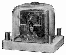
Fig. 476. Western Electric Selector View full size illustration.
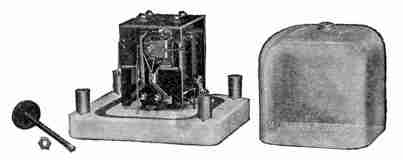
The Western Electric Selector. This selector is the latest and perhaps the simplest. Fig. 475 shows it with its glass dust-proof cover on, and Fig. 476 shows it with the cover removed. This selector is adapted for operating at high speed, stations being called at the rate of ten per second.
The operating mechanism, which is mounted on the front of the selector so as to be readily accessible, works on the central-energy principle—the battery for its operation, as well as for the operation of the bell used in connection with it, both being located at the dispatcher's office. The bell battery may, however, be placed at the waystation if this is desired.
The selector consists of two electromagnets which are bridged in series across the telephone circuit and are of very high impedance. It is possible to place as many of these selectors as may be desired across a circuit without seriously affecting the telephonic transmission. Direct-current impulses sent out by the dispatcher operate these magnets, one of which is slow and the other quick-acting. The first impulse sent out is a long impulse and pulls up both armatures, thereby causing the pawls above and below the small ratchet wheel, shown in Fig. 476, to engage with this wheel. The remaining impulses operate the quick-acting magnet and step the wheel around the proper number of teeth, but do not affect the slow-acting magnet which remains held up by them. The pawl connected to the slow-acting magnet merely serves to prevent the ratchet wheel from turning back. Attached to the ratchet wheel is a contact whose position can be varied in relation to the stationary contact on the left of the selector with which this engages. This contact is set so that when the wheel has been rotated the desired number of teeth, the two contacts will make and the bell be rung. Any selector may thus be adjusted for any station, and the selectors are thus interchangeable. When the current is removed from the line at the dispatcher's office, the armatures fall back and everything is restored to normal. An "answer-back" signal is provided with this selector dependent upon the operation of the bell. When the selector at a station operates, the bell normally rings for a few seconds. The dispatcher, however, can hold this ring for any length of time desired.
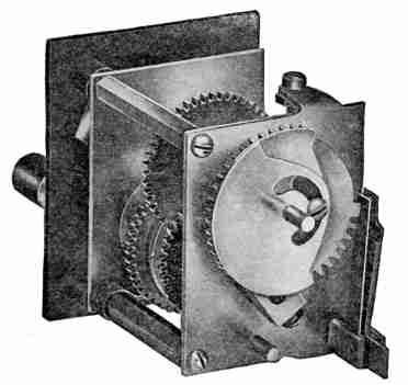
The keys employed at the dispatcher's office for operating selectors are shown in Fig. 477. There is one key for each waystation on the line and the dispatcher calls any station by merely giving the corresponding key a quarter turn to the right. Fig. 478 shows the mechanism of one of these keys and the means employed for sending out current impulses over the circuit. The key is adjustable and may be arranged for any station desired by means of the movable cams shown on the rear in Fig. 478, these cams, when occupying different positions, serving to cover different numbers of the teeth of the impulse wheel which operate the impulse contacts.
Fig. 477. Dispatcher's Keys View full size illustration.
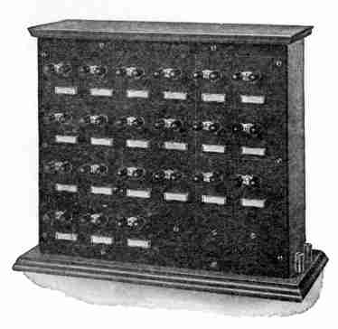
Fig. 478. Dispatcher's Key Mechanism View full size illustration.
The Gill Selector. The second type of selector in extensive use throughout the country today is known as the Gill, after its inventor. It is manufactured for both local-battery and central-energy types, the latter being the latest development of this selector. With the local-battery type, the waystation bell rings until stopped by the dispatcher. With the central-energy type it rings a definite length of time and can be held for a longer period as is the case with the Western Electric selector. The selector is operated by combinations of direct-current impulses which are sent out over the line by keys in the dispatcher's office.
Fig. 479. Gill Selector View full size illustration.
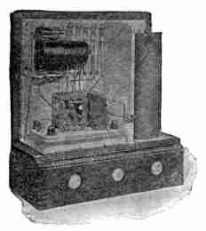
The dispatcher has a key cabinet, and calls in the same way as already described, but these keys instead of sending a series of quick impulses, send a succession of impulses with intervals between corresponding to the particular arrangement of teeth in the corresponding waystation selector wheel. Each key, therefore, belongs definitely with a certain selector and can be used in connection with no other.
A concrete example may make this clearer. The dispatcher may operate key No. 1421. This key starts a clockwork mechanism which impresses at regular intervals, on the telephone line, direct-current impulses, with intervals between as follows: 1-4-2-1. There is on the line one selector corresponding to this combination and it alone, of all the selectors on the circuit, will step its wheel clear around so that contact is made and the bell is rung. In all the others, the pawls will have slipped out at some point of the revolution and the wheels will have returned to their normal positions.
The Gill selector is shown in Fig. 479. It contains a double-wound relay which is bridged across the telephone circuit and operates the selector. This relay has a resistance of 4,500 ohms and a high impedance, and operates the selector mechanism which is a special modification of the ratchet and pawl principle. The essential features of this selector are the "step-up" selector wheel and a time wheel, normally held at the bottom of an inclined track.
The operation of the selector magnet pushes the time wheel up the track and allows it to roll down. If the magnet is operated rapidly, the wheel does not get clear down before being pushed back again. A small pin on the side of the pawl, engaging the selector wheel normally, opposes the selector wheel teeth near their outer points. When the time wheel rolls to the bottom of the track, however, the pawl is allowed to drop to the bottom of the tooth. Some of the teeth on the selector wheel are formed so that they will effectually engage with the pawl only when the latter is in normal position, while others will engage only while the pawl is at the bottom position; thus innumerable combinations can be made which will respond to certain combinations of rapid impulses with intervals between. The correct combination of impulses and intervals steps the selector wheel clear around so that a contact is made. The selector wheels at all other stations fail to reach their contact position because at some point or points in their revolution the pawls have slipped out, allowing the selector wheels to return "home."
The "answer-back" is provided in this selector by means of a few inductive turns of the bell circuit which are wound on the selector relay. The operation of the bell through these turns induces an alternating current in the selector winding which flows out on the line and is heard as a distinctive buzzing noise by the dispatcher.
Fig. 480. Cummings-Wray Dispatcher's Sender View full size illustration.
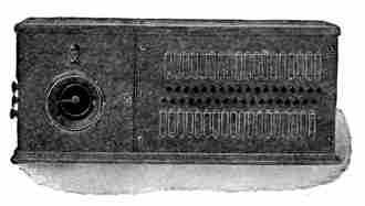
The Cummings-Wray Selector. Both of the selectors already described are of a type known as the individual-call selectors, meaning that only one station at a time can be called. If a plurality of calls is desired, the dispatcher calls one station after another. The third type of selector in use today is of a type known as the multiple-call, in which the dispatcher can call simultaneously as many stations as he desires.
The Cummings-Wray selector and that of the Kellogg Switchboard and Supply Company are of this type and operate on the principle of synchronous clocks. When the dispatcher wishes to put through a call, he throws the keys of all the stations that he desires and then operates a starting key. The bells at all these stations are rung by one operation.
The dispatcher's sending equipment of the Cummings-Wray system is shown in Fig. 480, and the waystation selector in Fig. 481. It is necessary with this system for the clocks at all stations to be wound every eight days.
Fig. 481. Cummings-Wray Selector View full size illustration.
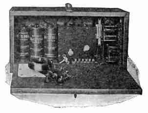
In the dispatcher's master sender the clock-work mechanism operates a contact arm which shows on the face of the sender in Fig. 480. There is one contact for every station on the line. The clock at this office and the clocks at all the waystation offices start together, and it is by this means that the stations are signaled, as will be described later, when the detailed operation of the circuits is taken up.
Telephone Equipment. Of no less importance than the selective devices is the telephone apparatus. That which is here illustrated is the product of the Western Electric Company, to whom we are indebted for all the illustrations in this chapter.
Dispatcher's Transmitter. The dispatcher, in most cases, uses the chest transmitter similar to that employed by switchboard operators in every-day service. He is connected at all times to the telephone circuit, and for this reason equipment easy for him to wear is essential. In very noisy locations he is equipped with a double head receiver. On account of the dispatcher being connected across the line permanently and of his being required to talk a large part of the time, there is a severe drain on the transmitter battery. For this reason storage batteries are generally used.
Fig. 482. Waystation Desk Telephone View full size illustration.
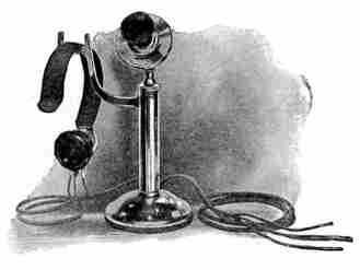
Waystation Telephones. At the waystations various types of telephone equipment may be used. Perhaps the most common is the familiar desk stand shown in Fig. 482, which, for railroad service, is arranged with a special hook-switch lever for use with a head receiver.
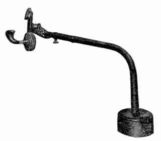
Often some of the familiar swinging-arm telephone supports are used, in connection with head receivers, but certain special types developed particularly for railway use are advantageous, because in many cases the operator who handles train orders is located in a tower where he must also attend to the interlocking signals, and for such service it is necessary for him to be able to get away from the telephone and back to it quickly. The Western Electric telephone arm developed for this use is shown in Fig. 483. In this the transmitter and the receiver are so disposed as to conform approximately to the shape of the operator's head. When the arm is thrown back out of the way it opens the transmitter circuit by means of a commutator in its base.
Fig. 483. Telephone Arm View full size illustration.
Siding Telephones. Two types of sets are employed for siding purposes. The first is an ordinary magneto wall instrument, which embodies the special apparatus and circuit features employed in the standard waystation sets. These are used only where it is possible to locate them indoors or in booths along the line. These sets are permanently connected to the train wire, and since the chances are small that more than one of them will be in use at a time, they are rung by the dispatcher, by means of a regular hand generator, when it is necessary for him to signal a switching.
Fig. 484. Weather-Proof Telephone Set View full size illustration.
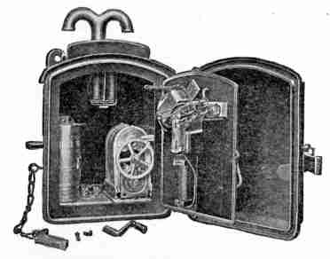
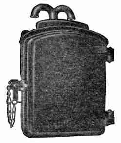
In certain cases it is not feasible to locate these siding telephone sets indoors, and to meet these conditions an iron weather-proof set is employed, as shown in Figs. 484 and 485. The apparatus in this set is treated with a moisture-proofing compound, and the casing itself is impervious to weather conditions.
Fig. 485. Weather-Proof Telephone Set View full size illustration.
Portable Train Sets. Portable telephone sets are being carried regularly on wrecking trains and their use is coming into more and more general acceptance on freight and passenger trains. Fig. 486 shows one of these sets equipped with a five-bar generator for calling the dispatcher. Fig. 487 shows a small set without generator for conductors' and inspectors' use on lines where the dispatcher is at all times connected in the circuit.
Fig. 486. Portable Telephone Set View full size illustration.
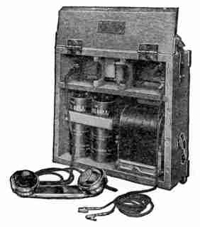
Fig. 487. Portable Telephone Set View full size illustration.
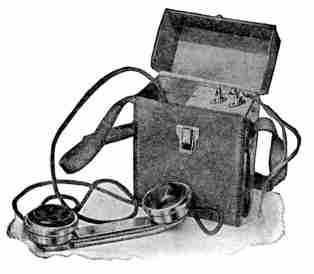
These sets are connected to the telephone circuit at any point on the line by means of a light portable pole arranged with terminals at its outer extremity for hooking over the line wires, and with flexible conducting cords leading to the portable set. The use of these sets among officials on their private cars, among construction and bridge gangs working on the line, and among telephone inspectors and repairmen for reporting trouble, is becoming more and more general.
Western Electric Circuits. As already stated, a telephone train-dispatching circuit may be from 25 to 300 miles in length, and upon this may be as many stations as can be handled by one dispatcher. The largest known number of stations upon an existing circuit of this character is 65.
Fig. 488. Dispatcher's Station—Western Electric System View full size illustration.
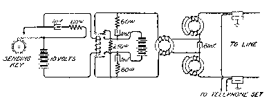
Dispatcher's Circuit Arrangement. The circuits of the dispatcher's station in the Western Electric system are shown in Fig. 488, the operation of which is briefly as follows: When the dispatcher wishes to call any particular station, he gives the key corresponding to that station a quarter turn. This sends out a series of rapid direct-current impulses on the telephone line through the contact of a special telegraph relay which is operated by the key in a local circuit. The telegraph relay is equipped with spark-eliminating condensers around its contacts and is of heavy construction throughout in order to carry properly the sending current.
Voltage. The voltage of the sending battery is dependent on the length of the line and the number of stations upon it. It ranges from 100 to 300 volts in most cases. When higher voltages are required in order successfully to operate the circuit, it is generally customary to install a telegraph repeater circuit at the center of the line, in order to keep the voltage within safe limits. One reason for limiting the voltage employed is that the condensers used in the circuit will not stand much higher potentials without danger of burning out. It is also possible to halve the voltage by placing the dispatcher in the center of the line, from which position he may signal in two directions instead of from one end.
Simultaneous Talking and Signaling. Retardation coils and condensers will be noticed in series with the circuit through which the signaling current must pass before going out on the line. These are for the purpose of absorbing the noise which is caused by high-voltage battery, thus enabling the dispatcher to talk and signal simultaneously. The 250-ohm resistance connected across the circuit through one back contact of the telegraph relay absorbs the discharge of the 6-microfarad condenser.
Fig. 489. Selector Set—Western Electric System View full size illustration.
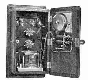
Waystation Circuit. The complete selector set for the waystations is shown in Fig. 489, and the wiring diagram of its apparatus in Fig. 490. The first impulse sent out by the key in the dispatcher's office is a long direct-current impulse, the first tooth being three or four times as wide as the other teeth. This impulse operates both magnets of the selector and attracts their armatures, which, in turn, cause two pawls to engage with the ratchet wheel, while the remaining quick impulses operate the "stepping-up" pawl and rotate the wheel the requisite number of teeth. Retardation coils are placed in series with the selector in order to choke back any lightning discharges which might come in over the line. The selector contact, when operated, closes a bell circuit, and it will be noted that both the selector and the bell are operated from battery current coming over the main line through variable resistances. There are, of course, a number of selectors bridged across the circuit, and the variable resistance at each station is so adjusted as to give each approximately 10 milliamperes, which allows a large factor of safety for line leakage in wet weather. The drop across the coils at 10 milliamperes is 38 volts. If these coils were not employed, it is clear that the selectors nearer the dispatcher would get most of the current and those further away very little.
Fig. 490. Selector Set—Western Electric System View full size illustration.
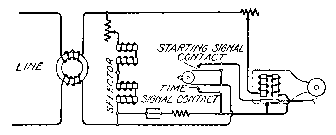
A time-signal contact is also indicated on the selector-circuit diagram of Fig. 490. This is common to all offices and may be operated by a special key in the dispatcher's office, thereby enabling him to send out time signals over the telephone circuit.
Fig. 491. Gill Dispatcher's Station View full size illustration.
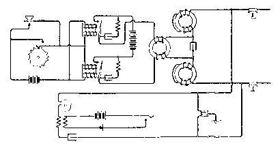
Gill Circuits. The circuit arrangement for the dispatcher's outfit of the Gill system is shown in Fig. 491. This is similar to that of the Western Electric system just described. The method of operation also is similar, the mechanical means of accomplishing the selection being the main point of difference. In Fig. 492 the wiring of the Gill selector at a waystation for local-battery service is shown. The selector contact closes the bell circuit in the station and a few windings of this circuit are located on the selector magnets, as shown. These provide the "answer-back" by inductive means.
Fig. 492. Gill Selector—Local Battery View full size illustration.
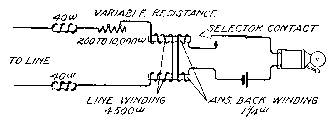
Fig. 493 shows the wiring of the waystation, central-energy Gill selector. In this case, the local battery for the operation of the bell is omitted and the bell is rung, as is the case of the Western Electric selector, by the main sending battery in the dispatcher's office.
Fig. 493. Gill Selector—Central Energy View full size illustration.
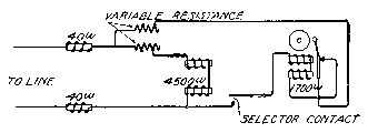
The sending keys of these two types of circuits differ, in that with the local-battery selector the key contact is open after the selector has operated, and the ringing of the bell must be stopped by the dispatcher pressing a button or calling another station. Either of these operations sends out a new current impulse which releases the selector and opens its circuit.
With the central-energy selector, however, the contacts of the sending key at the dispatcher's office remain closed after operation for a definite length of time. This is obviously necessary in order that battery may be kept on the line for the operation of the bell. In this case the contacts remain closed during a certain portion of the revolution of the key, and the bell stops ringing when that portion of the revolution is completed. If, however, the dispatcher desires to give any station a longer ring, he may do so by keeping the key contacts closed through an auxiliary strap key as soon as he hears the "answer-back" signal from the called station.
Cummings-Wray Circuits. The Cummings-Wray system, as previously stated, is of the multiple-call type, operating with synchronous clocks. Instead of operating one key after another in order to call a number of stations, all the keys are operated at once and a starting key sets the mechanism in motion which calls all these stations with one operation. Fig. 494 shows the circuit arrangement of this system.
Fig. 494. Cummings-Wray System View full size illustration.
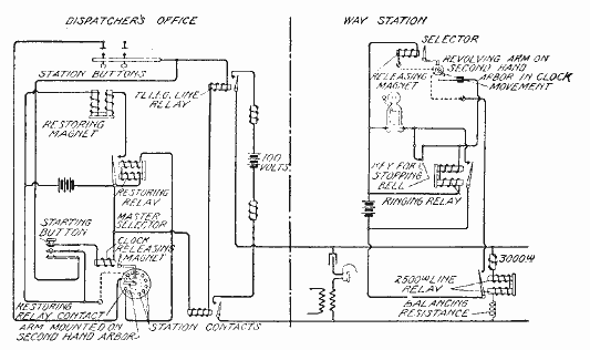
In order to ring one or more stations, the dispatcher presses the corresponding key or keys and then operates the starting key. This starting key maintains its contact for an appreciable length of time to allow the clock mechanism to get under way and get clear of the releasing magnet clutch. Closing the starting key operates the clock-releasing magnet and also operates the two telegraph-line relays. These send out an impulse of battery on the line operating the bridged 2,500-ohm line relays and, in turn, the selector releasing magnets; thus, all the waystation clocks start in unison with the master clock. The second hand arbor of each clock carries an arm, which at each waystation is set at a different angle with the normal position than that at any other station. Each of these arms makes contact precisely at the moment the master-clock arm is passing over the contact corresponding to that station.
If, now, a given station key is pressed in the master sender, the telegraph-line relays will again operate when the master-clock arm reaches that point, sending out another impulse of battery over the line. The selector contact at the waystation is closed at this moment; therefore, the closing of the relay contact operates the ringing relay through a local circuit, as shown. The ringing relay is immediately locked through its own contact, thus maintaining the bell circuit closed until it is opened by the key and the ringing is stopped.
As the master-clock arm passes the last point on the contact dial, the current flows through the restoring relay operating the restoring magnet which releases all the keys. A push button is provided by means of which the keys may be manually released, if desired. This is used in case the dispatcher presses a key by mistake. Retardation coils and variable resistances are provided at the waystation just as with the other selector systems which have been described and for the same reasons.
The circuits of the operator's telephone equipment shown in Fig. 495, are also bridged across the line. This apparatus is of high impedance and of a special design adapted to railroad service. There may be any number of telephones listening in upon a railroad train wire at the same time, and often a dispatcher calls in five or six at once to give orders. These conditions have necessitated the special circuit arrangement shown in Fig. 495.
Fig. 495. Telephone Circuits View full size illustration.
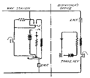
The receivers used at the waystations are of high impedance and are normally connected, through the hook switch, directly across the line in series with a condenser. When the operator, at a waystation wishes to talk, however, he presses the key shown. This puts the receiver across the line in series with the retardation coil and in parallel with the secondary of the induction coil. It closes the transmitter battery circuit at the same time through the primary of the induction coil.
The retardation coil is for the purpose of preventing excessive side tone, and it also increases the impedance of the receiver circuit, which is a shunt on the induction coil. This latter coil, however, is of a special design which permits just enough current to flow through the receiver to allow the dispatcher to interrupt a waystation operator when he is talking.
The key used to close the transmitter battery is operated by hand and is of a non-locking type. In some cases, where the operators are very busy, a foot switch is used in place of this key. The use of such a key or switch in practical operation has been found perfectly satisfactory, and it takes the operators but a short time to become used to it.
The circuits of the dispatcher's office are similarly arranged, Fig. 495, being designed especially to facilitate their operation. In other words, as the dispatcher is doing most of the work on the circuit, his receiver is of a low-impedance type, which gives him slightly better transmission than the waystations obtain. The key in his transmitter circuit is of the locking type, so that he does not have to hold it in while talking. This is for the reason that the dispatcher does most of the talking on this circuit. Foot switches are also employed in some cases by the dispatchers.
Test Boards. It is becoming quite a general practice among the railroads to install more than one telephone circuit along their rights-of-way. In many cases in addition to the train wire, a message circuit is also equipped, and quite frequently a block wire also operated by telephone, parallels these two. It is desirable on these circuits to be able to make simple tests and also to be able to patch one circuit with another in cases of emergency.
Fig. 496. Test Board View full size illustration.
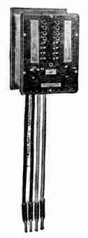
Test boards have been designed for facilitating this work. These consist of simple plug and jack boxes, the general appearance of which is shown in Fig. 496. The circuit arrangement of one of these is shown in Fig. 497. Each wire comes into an individual jack as will be noted on one side of the board, and passes through the inside contact of this jack, out through a similar jack on the opposite side. The selector and telephone set at an office are taken off these inside contacts through a key, as shown. The outside contacts of this key are wired across two pairs of cords. Now, assume the train wire comes in on jacks 1 and 3, and the message wire on jacks 9 and 11. In case of an accident to the train wire between two stations, it is desirable to patch this connection with a message wire in order to keep the all-important train wire working. The dispatcher instructs the operator at the last station which he can obtain, to insert plugs 1 and 2 in jacks 1 and 10, and plugs 3 and 4 in jacks 3 and 12, at the same time throwing the left-hand key. Then, obtaining an operator beyond the break by any available means, he instructs him likewise to insert plugs 1 and 2 in jacks 9 and 2, and plugs 3 and 4 in jacks 11 and 4, similarly throwing the left-hand key. By tracing this out, it will be observed that the train wire is patched over the disabled section by means of the message circuit, and that the selector and the telephone equipment are cut over on to the patched connections; in other words, bridged across the patching cords.
Fig. 497. Circuits of Test Board View full size illustration.
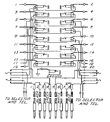
It will also be seen that with this board it is possible to open any circuit merely by plugging into a jack. Two wires can be short-circuited or a loop made by plugging two cords of corresponding colors into the two jacks. A ground jack is provided for grounding any wire. In this way, a very flexible arrangement of circuits is obtained, and it is possible to make any of the simple tests which are all that are usually required on this type of circuit.
Blocking Sets. As was just mentioned, quite frequently in addition to train wires and message circuits, block wires are also operated by telephone. In some cases separate telephone instruments are used for the blocking service, but in others the same man handles all three circuits over the same telephone. The block wire is generally a converted telegraph wire between stations, usually of iron and usually grounded. It seldom ranges in length over six miles.
Fig. 498. Blocking Set View full size illustration.
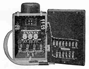
Where the block wires are operated as individual units with their own instruments, it is unnecessary to have any auxiliary apparatus to be used in connection with them. Where, however, they are operated as part of a system and the same telephone is used on these that is used on the train wire and message wire, additional apparatus, called a blocking set, is required. This blocking set, shown in Figs. 498 and 499, was developed especially for this service by the Western Electric Company. As will be noted, a repeating coil at the top and a key on the front of the set are wired in connection with a pair of train wire cords. This repeating coil is for use in connecting a grounded circuit to a metallic circuit, as, for instance, connecting a block wire to the train wire, and is, of course, for the purpose of eliminating noise. Below the key are three combined jacks and signals. One block wire comes into each of these and a private line may be brought into the middle one. When the next block rings up, a visual signal is displayed which operates a bell in the office by means of a local circuit. The operator answers by plugging the telephone cord extending from the bottom of the set into the proper jack. This automatically restores the signal and stops the bell.
Fig. 499. Blocking Set View full size illustration.
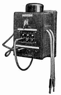
Below these signals appear four jacks. One is wired across the train wire; one across the message wire; and the other two are bridged across the two pairs of patching cords on each side of the set. The operator answers a call on any circuit by plugging his telephone cord into the proper jack.
If a waystation is not kept open in the evening, or the operator leaves it for any reason and locks up, he can connect two blocks together by means of the block-wire cords. These are arranged simply for connecting two grounded circuits together and serve to join two adjacent blocks, thereby eliminating one station. A jack is wired across these cords, so that the waystation operator can listen in on the connection if he so desires.
In some cases not only are the telephone circuits brought into the test board, but also two telegraph wires are looped through this board before going to the peg switchboard. This is becoming quite a frequent practice and, in times of great emergency, enables patches to be made to the telegraph wires as well as to the telephone wires.
Dispatching on Electric Railways. As interurban electric railways are becoming more extended, and as their traffic is becoming heavier, they approximate more closely to steam methods of operation. It is not unusual for an electric railway to dispatch its cars exactly as in the case of a steam road. There is a tendency, however, in this class of work, toward slightly different methods, and these will be briefly outlined.
On those electric railways where the traffic is not especially heavy, an ordinary magneto telephone line is frequently employed with standard magneto instruments. In some cases the telephone sets are placed in waiting rooms or booths along the line of the road. In other cases it is not feasible to locate the telephone indoors and then iron weather-proof sets, such as are shown in Figs. 484 and 485, are mounted directly on the poles along the line of railway. With a line of this character there is usually some central point from which orders are issued and the trainmen call this number when arriving at sidings or wherever they may need to do so.
Another method of installing a telephone system upon electric railways is as follows: Instead of instruments being mounted in booths or on poles along the line, portable telephone sets are carried on the cars and jacks are located at regular intervals along the right-of-way on the poles. The crew of the car wishing to get in touch with the central office or the dispatcher, plugs into one of these jacks and uses the portable telephone set. At indoor stations, in offices or buildings belonging to the railroad, the regular magneto sets may be employed, as in the first case outlined.
On electric railway systems where the traffic is heavy, the train or car movements may be handled by a dispatcher just as on the steam railroad. There is usually one difference, however. On a steam road, the operators who give the train crews their orders and manipulate the semaphore signals are located at regular intervals in the different waystations. No such operators are usually found on electric railways, except, perhaps, at very important points, and, therefore, it is necessary for the dispatcher to be able to signal cars at any point and to get into communication with the crews of these cars. He does this by means of semaphores operated by telephone selectors over the telephone line. The telephone circuit may be equipped with any number of selectors desired, and the dispatcher can operate any particular one without operating any other one on the circuit. Each selector, when operated, closes a pair of contacts. This completes a local circuit which throws the semaphore arm to the "danger" position, at the same time giving the dispatcher a distinctive buzz in his ear, which informs him that the arm has actually moved to this position. He can get this signal only by the operation of the arm.
Each semaphore is located adjacent to a telephone booth in which is also placed the restoring lever, by means of which the semaphore is set in the "clear" position by the crew of the car which has been signaled. The wall-type telephone set is usually employed for this class of service, but if desired, desk stands or any of the various transmitter arms may be used.
It is necessary for the crew of the car which first approaches a semaphore set at "danger," to get out, communicate with the dispatcher, and restore the signal to the "clear" position. The dispatcher can not restore the signal. The signal is set only in order that the train crew may get into telephonic communication with the dispatcher, and in order to do this, it is necessary for them to go into the booth in any case.
ToC