Volume 2 — CHAPTER XXIX THE AUTOMATIC ELECTRIC COMPANY'S SYSTEM (continued 2)
Reading edition
Fig. 397. Circuits of Trunk Repeater View full size illustration.
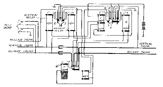
The circuits of a trunk repeater are shown in Fig. 397. In considering it, it must be understood that the three wires entering the figure at the left are the vertical, rotary, and release wires of a second selector trunk leading from the first selector banks in the same office. The two wires leading from the right of the figure are those extending to the distant office, and terminate there in second selectors. The vertical and the rotary sides of this trunk as shown at the left will receive the impulses from the subscriber's station coming through the line switch and the first selector, as usual. The vertical impulses will pass through the winding of the vertical relay and through the winding 1 of the calling battery supply relay and thence to battery, the same as on a connector. These impulses will work the armatures of both of these relays in unison. The movements of the vertical relay armature in response to these impulses will cause corresponding impulses to flow over a circuit which may be traced from ground, through the springs 3 and 2 of the vertical relay, the springs 4 and 5 of the bridged relay 6 and thence to the vertical side of the trunk and to the distant office, where it passes into a second selector and through its vertical relay to battery. Thus the vertical impulses are passed on over the two-wire trunk to the second selector at the distant office. It becomes necessary, however, to prevent these impulses from passing back through the winding of the bridge relay 6 and this is done by means of the sluggish relay 7. This relay receives local battery impulses in unison with those sent over the trunk by the vertical relay, these being supplied from the battery at the local office through the contacts 8 and 9 of the calling battery supply relay, which works in unison with the vertical relay. These rapidly recurring impulses are too fast for the sluggish relay 7 to follow. And this relay merely pulls up its armature and cuts off both sides of the trunk leading back to the first selector. The rotary impulses are repeated to the rotary side of the two-wire trunk in a similar way.
Considering now the operation of the trunk repeater in the reverse direction, the action of the bridging relay 6 is of vital importance. Normally both sides of trunk line are connected to the live side of the battery and, therefore, there is no difference of potential between them and no tendency to operate the bridged relay. When the connection has been fully established to the subscriber at the distant office, and that subscriber has responded, the action of his battery supply relay will, as before stated, change the connection of the rotary side of the line from battery to ground, and thus bridge the battery at the distant exchange across the trunk. This action will pull up the bridged relay 6 at the trunk repeater and will perform exactly the same function with respect to the connection of the battery with the calling subscriber's line. In other words, it will change the connection of the rotary side of the calling line from battery to ground, thus establishing the necessary difference in potential to give the calling subscriber the necessary current for transmission purposes. The disconnect feature is about the same as already described. When the calling subscriber hangs up his receiver both the vertical and rotary relays of the trunk repeater operate, which places the ground on both sides of the two-wire trunk to the distant office, which is the condition for releasing all of the apparatus there.
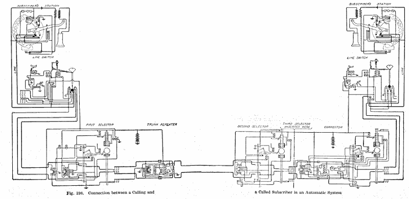
For the purpose of convenience the simplified diagram of Fig. 398 has been prepared, which shows the complete connection from a calling subscriber to a called subscriber in a multi-office exchange, wherein the first movement of the dial is employed to establish the connection to the proper office and the four succeeding movements to make a selection among ten thousand lines in that office. This circuit, therefore, employs at the first office the line switch, the first selector, and the trunk repeater; and at the second office the second selector, third selector, connector, and line switch.
The third selector is omitted from Fig. 398, but this will cause no confusion, since it is exactly like the second selector. The circuits shown are exactly like those previously described but in drawing them the main idea has been to simplify the connections to the greatest possible extent at a sacrifice in the clearness with which the mechanical inter-relation of parts is shown. No correct understanding of the circuits of an automatic system is possible without a clear idea of the mechanical functions performed by the different parts, and, therefore, we have described what are apparently the more complex circuit drawings first. It is believed that the student, in attempting to gain an understanding of this marvel of mechanical and electrical intricacy, will find his task less burdensome if he will refer freely to both the simplified circuit drawing of Fig. 398 and the more complex ones preceding it. By doing so he will often be enabled to clear up a doubtful circuit point from the simpler diagram and a doubtful mechanical point from those diagrams which represent more clearly the mechanical relation of parts.
Fig. 398. Connection between a Calling and a Called Subscriber in an Automatic System View full size illustration.
Automatic Sub-Offices. Obviously, the system of trunking employed in automatic exchanges lends itself with great facility to the subdivision of an exchange into a large number of comparatively small office districts and the establishment of branch offices or sub-offices at the centers of these districts.
The trunking between large offices has already been described. An attractive feature of the automatic system is the establishment of so-called sub-stations or sub-offices. Where there is, in an outlying district, a distinct group of subscribers whose lines may readily be centered at a common point within that district and where the number of such subscribers and lines is insufficient to establish a fully equipped office, it is possible to establish a so-called sub-station or sub-office connected with the main office of that district by trunk lines. At this sub-office there are placed only line switches and connectors. When a call is originated on one of these sub-office lines, the line switch acts instantly to connect that line with one of the trunks leading to the main office of that district, at which this trunk terminates in a first selector. From there on, the connection is the same as that in a system in which no sub-offices are employed. Calls coming into this sub-office over trunk lines from the main office are received on the connectors at the sub-office and the connection is made with the sub-office line by the connector in the usual manner. This arrangement, it is seen, amounts merely to a stretching of the connector trunks for a given group of lines so that they will reach out from a main office to a sub-office, it being more economical to lengthen the smaller number of trunks and by so doing to decrease in length the larger number of subscribers' lines.
The Rotary Connector. For certain purposes it becomes desirable in automatic work to employ a special form of connector which will have in itself a certain ability to make automatic selection of one of a group of previously chosen trunks in much the same manner as the first and second selectors automatically choose the first idle one of a group of trunks.
Such a use is demanded in private branch-exchange working where a given business establishment, for instance, has a plurality of lines connecting its own private switchboard with the central office. The directory number of all these lines is, for convenience, made the same, and it is important, therefore, that when a person attempts to make a connection with this establishment, he will not fail to get his connection simply because the first one of these lines happens to be busy. For such use a given horizontal row of connector terminals or a part of such a row is assigned to the lines leading to the private branch exchange and the connector is so modified as to have a certain "discretionary" power of its own. As a result, when the common number of all these lines is called, the connector will choose the first one, if it is not already engaged by some other connector, but if it is, it will pass on to the next, and so on until an idle one is found. It is only when the connector has hunted through the entire group of lines and found them all busy that it will refuse to connect and will give the busy signal to the calling subscriber.
Party Lines. The description of this system as given above has been confined entirely to direct line working; however, party lines may be and are frequently employed.
The circuits and apparatus used with direct lines are, with slight modifications, applicable to use with party lines.
The harmonic method of ringing is employed and the stations are so arranged with respect to the connectors that those requiring the same frequency for ringing the bells are in groups served by the same set of connectors.
The party lines are operated on the principle commonly known in manual practice as the jack per station arrangement. Each party line will, therefore, have sets of terminals appearing in separate hundreds; the connectors associated with each of these hundreds being so arranged as to impress the proper frequency of ringing current on the line.
From the subscribers' standpoint the operation is the same as for direct lines, as the particular hundreds digit of a number serves to select one of a group of connectors capable of connecting the proper ringing current to the line.
To avoid confusion, which would be caused by a subscriber on a party line attempting to make a call when the line is already in use by some other subscriber, the subscribers' stations are so arranged that when the line is in use all other stations on the line are locked out.
Fig. 399. Wall Set for Two-Wire System View full size illustration.
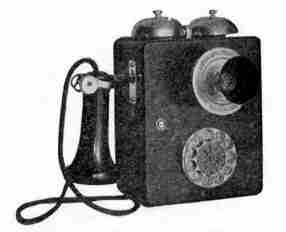
The Two-Wire Automatic System. The two-wire system that has recently been introduced by the Automatic Electric Company brings about the very important result of accomplishing all of the automatic switching over metallic circuit lines without the use of ground or common returns. The system is thus relieved of the disturbing influences to which the three-wire system is sometimes subjected, due to differences in earth potential between various portions of the system, which may add to or subtract from the battery potential and alter the net potential available between two distant points. The introduction of this system has also made possible certain other incidental features of advantage, one of which is a great simplification and reduction in size of the subscriber's station signal-transmitting apparatus.
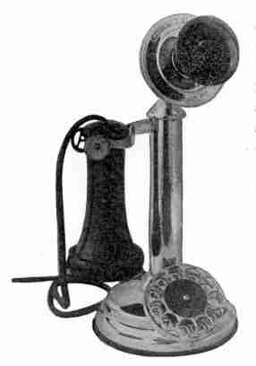
With the doing away of the ground as a return circuit, it becomes impossible to send vertical impulses over one side of the line and to follow them by single rotary impulses over the other side of the line. Yet it becomes necessary to distinguish between the pure selective impulses and those impulses which dictate a change of function at the central office. The plan has, therefore, been adopted of accomplishing the selection in each case by short and rapidly recurring impulses and of accomplishing those functions formerly brought about by the single impulse over the rotary side of the line by a pause between the respective series of selective impulses. This is accomplished at the central office by replacing the vertical and the rotary relays of the three-wire system by a quick-acting and a sluggish relay, respectively; the quick-acting relay performing the functions previously carried out by the vertical relay, and the sluggish relay acting only during the pauses between the successive series of quick impulses to do the things formerly done by the rotary relay. This has resulted in a delightful simplification of subscriber's apparatus, since it is now necessary only to provide a device which will connect the two sides of the line together the required number of times in quick succession and then allow a pause with the circuit closed while the subscriber is getting ready to transmit another set of impulses corresponding to another digit. The calling device has no mechanical function co-acting with any of the other parts of the telephone and may be considered as a separate mechanical device electrically connected with the line. The transmitting device is not much larger than a large watch and a good idea of it may be had from Fig. 399, which shows the latest wall set, and Fig. 400, which shows the latest desk set of the Automatic Electric Company. We regret the fact that this company has made the request that the complete details of their two-wire system be not published at this time.
Fig. 400. Desk Stand for Two-Wire System View full size illustration.
ToC