Volume 2 — CHAPTER XXIX THE AUTOMATIC ELECTRIC COMPANY'S SYSTEM
Reading edition
Almost wherever automatic telephony is to be found—and its use is extensive and rapidly growing—the so-called Strowger system is employed. It is so named because it is the outgrowth of the work of Almon B. Strowger, an early inventor in the automatic telephone art. That the system should bear the name of Strowger, however, gives too great prominence to his work and too little to that of the engineers of the Automatic Electric Company under the leadership of Alexander E. Keith.
Principles of Selecting Switch. The underlying features of this automatic system have already been referred to in the abstract. A better grasp of its principles may, however, be had by considering a concrete example of its most important piece of apparatus—the selecting switch. The bare skeleton of such a switch, sufficient only to illustrate the salient point in its mode of operation, is shown in Fig. 380. The essential elements of this are a vertical shaft capable of both longitudinal and rotary motion; a pawl and ratchet mechanism actuated by a magnet for moving the shaft vertically a step at a time; another pawl and ratchet mechanism actuated by another magnet for rotating the shaft a step at a time; an arm carrying wiper contacts on its outer end, mounted on and moving with the shaft; and a bank of contacts arranged on the inner surface of a section of a cylinder adapted to be engaged by the wiper contacts on this movable arm.
These various elements are indicated in the merest outline and with much distortion in Fig. 380, which is intended to illustrate the principles of operation rather than the details as they actually are in the system. In the upper left-hand corner of this figure, the magnet shown will, if energized by impulses of current, attract and release its armature and, in doing so, cause the pawl controlled by this magnet to move the vertical shaft of the switch up a step at a time, as many steps as there are impulses of current. The vertical movement of this shaft will carry the wiper arm, attached to the lower end of the shaft, up the same number of steps and, in doing so, will bring the contacts of this wiper arm opposite, but not engaging, the corresponding row of stationary contacts in the semi-cylindrical bank. Likewise, through the ratchet cylinder on the intermediate portion of the shaft, the magnet shown at the right-hand portion of this figure will, when energized by a succession of electrical impulses, rotate the shaft a step at a time, as many steps as there are impulses. This will thus cause the contacts of the wiper arm to move over the successive contacts in the row opposite to which the wiper had been carried in its vertical movement.
Fig. 380. Principles of Automatic Switch View full size illustration.
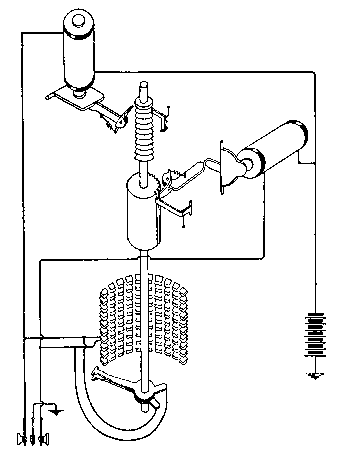
At the lower left-hand corner of this figure, there is shown a pair of keys either one of which, when operated, will complete the circuit of the magnet to which it is connected, this circuit including a common battery. In a certain rough way this pair of key switches in the lower left-hand corner of the drawing may be taken as representing the call-transmitting apparatus at the subscriber's station, and the two wires extending therefrom may be taken as representing the line wires connecting that subscriber's station to the central office; but the student must avoid interpreting them as actual representations of the subscriber's station calling apparatus or the subscriber's line since their counterparts are not to be found in the system as it really exists. Here again accuracy has been sacrificed for ease in setting forth a feature of operation.
Still referring to Fig. 380, it will be seen that the bank contacts consist of ten rows, each having ten pairs of contacts. Assume again, for the sake of simplicity, that the exchange under consideration has one hundred subscribers and that each pair of bank contacts represents the terminals of one subscriber's line. Assume further that the key switches in the lower left-hand corner of the figure are being manipulated by a subscriber at that station and that he wishes to obtain a connection with line No. 67. By pressing and releasing the left-hand key six times, he will cause six separate impulses of current to flow through the upper left-hand magnet and this will cause the switch shaft to move up six steps and bring the wiper arm opposite the sixth row of bank contacts. If he now presses and releases his right-hand key seven times, he will, through the action of the right-hand magnet, rotate the shaft seven steps, thus bringing the wipers into contact with the seventh contact of the sixth row and thus into contact with the desired line. As the wiper contacts on the switch arm form the terminals of the calling subscriber's line, it will be apparent that the calling subscriber is now connected through his switch with the line of subscriber No. 67.
As stated, each of the pairs of bank contacts are connected with the line of a subscriber; the line, Fig. 380, is shown so connected to the forty-first pair of contacts, that is to the first contact in the fourth row. The selecting switch shown in Fig. 380 would be for the sole use of the subscriber on the line No. 41. Each of the other subscribers would have a similar switch for his own exclusive use. Since any of the switches must be capable of reaching line No. 67, for instance, when moved up six rows and around seven, it follows that the sixty-seventh pair of contacts in each bank of the entire one hundred switches must also be connected together and to line No. 67. The same is, of course, true of all the contacts corresponding to any other number. Multiple connections are thus involved between the corresponding contacts of the banks, in much the same way as in the corresponding jacks in the multiple of a manual switchboard. As a result of this multiple connection of the bank contacts, any subscriber may move the wiper arm of his selecting switch into connection with the line of any other subscriber.
The "Up-and-Around" Movement. The elemental idea to be grasped by the discussion so far, is the so-called "up-and-around" method of action of the selecting switches employed in this system. This preliminary discussion may be carried a step further by saying that the arrangement is such that when a subscriber presses both his keys and grounds both of the limbs of his line, such a condition is brought about as will cause all holding pawls to be withdrawn from the shaft, and thus allow it to return to its normal position with respect to both its vertical and rotary movements. No attempt has been made in Fig. 380 to show how this is accomplished.
Function of Line Switch. Such a system as has been briefly outlined in the foregoing would require a separate selecting switch for each subscriber's line and would be limited to use in exchanges having not more than one hundred lines. In the modern system of the Automatic Electric Company, the requirement that each subscriber shall have a selective switch, individual to his own line, has been eliminated by introducing what is called an individual line switch by means of which any one of a group of subscribers' lines, making a call, automatically appropriates one of a smaller group of selecting switches and makes it its own only while the connection exists.
Subdivision of Subscribers' Lines. The limitation as to the size of the exchange has been overcome, without increasing the number of bank contacts in any selecting switch, by dividing the subscribers' lines into groups of one hundred and causing selecting switches automatically to extend the calling subscriber's line first into a group of groups corresponding, for instance, to the thousand containing the called subscriber's line, and then into the particular group containing the line, and lastly, to connect with the individual line in that group.
Underlying Feature of Trunking System. It will be remembered that in the chapter on fundamental principles of automatic systems, it was stated that the subscriber, by means of the signal transmitter at his station, was made to govern the action of the central-office apparatus in the selection of a proper group of trunks; and the group being selected, the central-office apparatus was made to act automatically to pick out and connect with the first idle trunk of such group. This selection by the subscriber of a group followed by the automatic selection from among that group forms the basis of the trunking system. It is impossible, by means of any simple diagram, to show a complete scheme of trunking employed, but Fig. 381 will give a fundamental conception of it. This figure shows how a single calling line, indicated at the bottom, may find access into any particular line in an office having a capacity for ten thousand.
Names of Selecting Switches. Selecting switches of the "up-and-around" type are the means by which the calling line selects and connects with the trunk lines required in building up the connection, and finally selects and connects with the line of the called subscriber. Where such a switch is employed for the purpose of selecting a trunk, it is called a selector switch. It is a first selector when it serves to pick out a major group of lines, i. e., a group containing a particular thousand lines or, in a multi-office system, a group represented by a complete central office. It is a second selector when it serves to make the next subdivision of groups; a third selector if further subdivision of groups is necessary; and finally it is a connector when it is employed to pick out and connect with the particular line in the final group of one hundred lines to which the connection has been brought by the selectors. In a single office of 10,000-line capacity, therefore, we would have first and second selectors and connectors, the first selectors picking out the thousands, the second selectors the hundreds, and the connectors the individual line. In a multi-office system we may have first, second, and third selectors and connectors, the first selector picking out the office, the second selector the thousands in that office, the third selector the hundreds, and the connector the individual lines.
The Line Switch. In addition to the selectors and connectors there are line switches, which are comparatively simple, one individual to each line. Each of these has the function, purely automatic, of always connecting a line, as soon as a call is originated on it, to some one of a smaller group of first selectors available to that line. This idea may be better grasped when it is understood that, in the earlier systems of the Automatic Electric Company, there was a first selector permanently associated with each line. By the addition of the comparatively simple line switch, a saving of about ninety per cent of the first selectors was effected, since the number of first selectors was thereby reduced from a number equal to the number of lines in a group to a number equal to the number of simultaneous connections resulting from calls originating in that group. In other words, by the line switch, the number of first selectors is determined by the traffic rather than by the number of lines.
Scheme of Trunking. With this understanding as to the names and broader functions of the things involved, Fig. 381 may now be understood. The line switch of the single line, as indicated here, has only the power of selection among three trunks, but it is to be understood that in actual practice, it would have access to a greater number, usually ten. So, also, throughout this diagram we have shown the apparatus and trunks arranged in groups of three instead of in groups of ten, only the first three thousands groups being indicated and the first three hundreds groups in each thousand. Again only three levels instead of ten are indicated for each selecting switch, it being understood that in the diagram the various levels are represented by concentric arcs of circles, and the trunk contacts by dots on these arcs.
Line-Switch Action. When the subscriber, whose line is shown at the bottom of the figure, begins to make a call, the line switch acts to connect his line with one of the first selector trunks available to it. This selection is entirely preliminary and, except to start it, is in no way under the control of the calling subscriber. The calling line now has under its control a first selector which, for the time being, becomes individual to it. Let it be assumed that the line switch found the first of the first selector trunks already appropriated by some other switch, but that the second one of these trunks was found idle. This trunk being appropriated by the line switch places the center one of the first selectors shown under the control of the subscriber's line. This first selector then acts in response to the first set of selective impulses sent out by his signal transmitter.
Fig. 381. Scheme of Trunking View full size illustration.
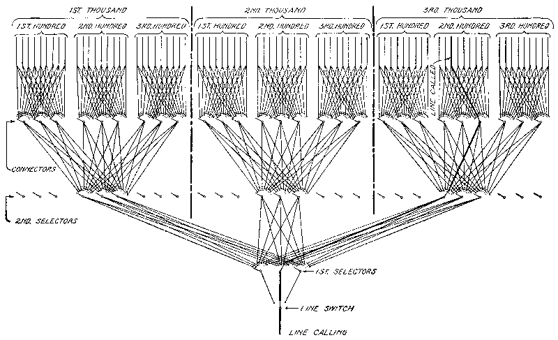
First Selector Action. We will assume that the calling subscriber desires to connect with No. 3213. The first movement of the subscriber's signal transmitter will send, therefore, three impulses over the line. These impulses will act on the vertical magnet of the first selector switch to move it up three steps. On this "level" of the contact bank of this switch all of the contacts will represent second selector trunks leading to the third thousand group. The other ends of these trunks will terminate in the wipers and also in the controlling magnets of second selectors serving this thousand. This function on the part of the first selector controlled by the act of the subscriber will have thus selected a group of trunks leading to the third thousand, but the subscriber has nothing to do with which one of the trunks of this group will actually be used. Immediately following the vertical movement of the first selector switch the rotary movement of this switch will start and will continue until the wipers of that switch have found contacts of an idle trunk leading to a second selector. Assuming that the first trunk was the one found idle, the first selector wipers would pause on the first pair of contacts in the third level of its bank, and the trunk chosen may be seen leading from that contact off to the group of second selectors belonging to the third thousand. For clearness, the chosen trunks in this assumed connection are shown heavier than the others.
Second Selector Action. The next movement of the dial by the subscriber in establishing his desired connection will send two impulses, it being desired to choose the second hundred in the third thousand. The first selector will have become inoperative before this second series of impulses is sent and, therefore, only the second selector will respond. Its vertical magnet acting under the influence of these two impulses will step up its wiper contacts opposite the second row of bank contacts, and the subscriber will thus have chosen the group of trunks leading to the second hundred in the third thousand. Here, again, the automatic operation of picking out the first idle one of this chosen group of trunks will take place without the volition of the subscriber, and it will be assumed that the first two trunks on this level of the second selector were found already engaged and that the third was therefore chosen. The connection continues, as indicated by heavy lines in Fig. 381, to the third one of the connectors in the second hundred of the third thousand. Any one of these connectors would have accomplished the purpose but this is assumed to be the first one found idle by the second selector.
Connector Action. The third movement of the subscriber's dial will send but one impulse, this corresponding to the first group of ten in the second hundred in the third thousand. This impulse will move the connector shaft up to the first level of bank contacts; and from now on the action of the connector differs radically from that of the selectors. The connector is not searching for an idle trunk in the group but for a particular line and, therefore, having chosen the group of ten lines in the desired hundred, the connector switch waits for further guidance from the subscriber. This comes in the form of the final set of impulses sent by the subscriber's signal transmitter which, in this case, will be three in number, corresponding to the final digit in the number of the called subscriber. This series of impulses will control the rotary movement of the connector wipers which will move along the first level and stop on the third one. The process is seen to be one of successive selection, first of a large group, then of a smaller, again of a smaller, and finally of an individual.
If the line is found not busy, the connection between the two subscribers is complete and the called subscriber's bell will be rung. If it is found busy, however, the connector will refuse to connect and will drop back to its normal position, sending a busy signal back to the calling subscriber. The details of ringing and the busy-back operation may only be understood by a discussion of drawings, subsequently to be referred to.
Two-Wire and Three-Wire Systems. In most of the systems of the Automatic Electric Company in use today the impulses by which the subscriber controls the central-office apparatus flow over one side of the line or the other and return by ground. The metallic circuit is used for talking and for ringing the called subscriber's bell, while ground return circuits, on one side of the line or the other, are used for sending all the switch controlling impulses.
Recently this company has perfected a system wherein no ground is required at the subscriber's station and no ground return path is used for any purpose between the subscriber and the central office. This later system is known as the "two-wire" system, and in contra-distinction to it, the earlier and most used system has been referred to as the "three-wire." It is not meant by this that the line circuits actually have three wires but that each line employs three conductors, the two wires of the line and the earth. The three-wire system will be referred to and described in detail, and from it the principles of the two-wire system will be readily understood.
Fig. 382. Automatic Wall Set View full size illustration.
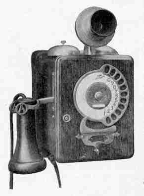
Fig. 383. Automatic Desk Stand View full size illustration.
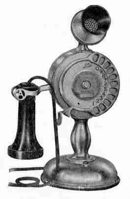
Subscriber's Station Apparatus. The detailed operation of the three-wire system may be best understood by considering the subscriber's station apparatus first. The general appearance of the wall set is shown in Fig. 382, and of the desk set in Fig. 383. These instruments embody the usual talking and call-receiving apparatus of a common-battery telephone and in addition to this, the signal transmitter, which is the thing especially to be considered now. The diagrammatic illustration of the signal transmitter and of the relation that its parts bear to the other elements of the telephone set is shown in Fig. 384. It has already been stated that the subscriber manipulates the signal transmitter by rotating the dial on the face of the instrument. A clearer idea of this dial and of the finger stop for it may be obtained from Figs. 382 and 383.
Fig. 384. Circuits of Telephone Set View full size illustration.
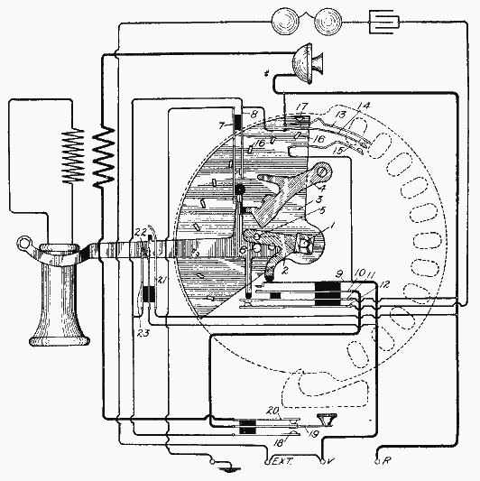
Operation. To make a call for a given number the subscriber removes his receiver from its hook, then places his forefinger in the hole opposite the number corresponding to the first digit of the desired number. By means of the grip thus secured, he rotates the dial until its movement is stopped by the impact of the finger against the stop. The dial is then released and in its return movement it sends the number of impulses corresponding to the first digit in the called number. A similar movement is made for each digit.
In Fig. 384 is given a phantom view of the dial, in order to show more clearly the relation of the mechanical parts and contacts controlled by it. For a correct idea of its mechanical action it must be understood that the shaft 1, the lever 2, and the interrupter segment 3 are all rigidly fastened to the dial and move with it. A coiled spring always tends to move the dial and these associated parts back to their normal positions when released by the subscriber, and a centrifugal governor, not shown, limits the speed of the return movement.
The subscriber's hook switch is mechanically interlocked with the dial so as to prevent the dial being moved from its normal position until the hook is in its raised position. This interlocking function involves also the pivoted dog 4. Normally the lower end of this dog lies in the path of the pin 5 carried on the lever 2, and thus the shaft, dial, and segment are prevented from any considerable movement when the receiver is on the hook. However, when the receiver is removed from its hook, the upwardly projecting arm from the hook engages a projection on the dog 4 and moves the dog out of the path of the pin 5. Thus the dial is free to be rotated by the subscriber. The pin 6 is mounted in a stationary position and serves to limit the backward movement of the dial by the lever 2 striking against it.
Ground Springs:—Five groups of contact springs must be considered, some of which are controlled wholly by the position of the switch hook, others jointly by the position of the switch hook and the dial, others by the movement of the dial itself, and still others by the pressure of the subscriber's finger on a button. The first of these groups consists of the springs 7 and 8, the function of which is to control the continuity of the ground connection at the subscriber's station. The arrangement of these two springs is such that the ground connection will be broken until the subscriber's receiver is removed from its hook. As soon as the receiver is raised, these springs come together in an obvious manner, the dog 4 being lifted out of the way by the action of the hook. The ledge on the lower portion of the spring 7 serves as a rest for the insulated arm of the dog 4 to prevent this dog, which is spring actuated, from returning and locking the dial until after the receiver has been hung up.
Bell and Transmitter Springs:—The second group is that embracing the springs 9, 10, 11, and 12. The springs 10 and 11 are controlled by the lower projection from the switch hook, the spring 11 engaging the spring 12 only when the hook is down. The spring 10 engages the spring 9 only when the hook lever is up and not then unless the dial is in its normal position. While the hook is raised, therefore, the springs 9 and 10 break contact whenever the dial is moved and make contact again when it returns to its normal position. The springs 11 and 12 control the circuit through the subscriber's bell while the springs 9 and 10 control the continuity of the circuit from one side of the line to the other so as to isolate the limbs from each other while the signal transmitter is sending its impulses to the central office.
Impulse Springs:—The third group embraces springs 13, 14, and 15 and these are the ones by which the central-office switches are controlled in building up a connection.
Something of the prevailing nomenclature which has grown up about the automatic system may be introduced at this point. The movements of the selecting switches at the central office are referred to as vertical and rotary for obvious reasons. On account of this the magnet which causes the vertical movement is referred to as the vertical magnet and that which accomplishes the rotary movement as the rotary magnet. It happens that in all cases the selecting impulses sent by the subscriber's station, corresponding respectively to the number of digits in the called subscriber's number, are sent over one side of the line and in nearly all cases these selecting impulses actuate the vertical movements of the selecting switches. For this reason the particular limb of the line over which the selecting impulses are sent is called the vertical limb. The other limb of the line is the one over which the single impulse is sent after each group of selecting impulses, and it is this impulse in every case which causes the selector switch to start rotating in its hunt for an idle trunk. This side of the line is, therefore, called rotary. For the same reasons the impulses over the vertical side of the line are called vertical impulses and those over the rotary side, rotary impulses. The naming of the limbs of the line and of the current impulses vertical and rotary may appear odd but it is, to say the least, convenient and expressive.
Coming back to the functions of the third group of springs, 13, 14, and 15, 15 may be called the vertical spring since it sends vertical impulses; 13, the rotary spring since it sends rotary impulses; and 14, the ground spring since, when the hook is up, it is connected with the ground.
On the segment 3 there are ten projections or cams 16 which, when the dial is moved, engage a projection of the spring 15. When the dial is being pulled by the subscriber's finger, these cams engage the spring 15 in such a way as to move it away from the ground spring and no electrical contact is made. On the return of the dial, however, these cams engage the projection on the spring 15 in the opposite way and the passing of each cam forces this vertical spring into engagement with the ground spring. It will readily be seen, therefore, by a consideration of the spacing of these cams on the segment and the finger holes in the dial that the number of cams which pass the vertical spring 15 will correspond to the number on the hole used by the subscriber in moving the dial.
Near the upper right-hand corner of the segment 3, as shown in Fig. 384, there is another projection or cam 17, the function of which is to engage the rotary spring 13 and press it into contact with the ground spring. Thus, the first thing that happens in the movement of the dial is for the projection 17 to ride over the hump on the rotary spring and press the contact once into engagement with the ground spring; and likewise, the last thing that happens on the return movement of the dial is for the rotary spring to be connected once to the ground spring after the last vertical impulse has been sent.
If both the rotary and vertical sides of the line are connected with the live side of the central-office battery, it follows that every contact between the vertical and the ground spring or between the rotary and the ground spring will allow an impulse of current to flow over the vertical or the rotary side of the line.
We may summarize the action of these impulse springs by saying that whenever the dial is moved from its normal position, there is, at the beginning of this movement, a single rotary impulse over the rotary side of the line; and that while the dial returns, there is a series of vertical impulses over the vertical side of the line; and just before the dial reaches its normal position, after the sending of the last vertical impulse, there is another impulse over the rotary side of the line.
The mechanical arrangements of the interrupter segment 3 and its associated parts have been greatly distorted in Fig. 384 in order to make clear their mode of operation. This drawing has been worked out with great care, with this in mind, at a sacrifice of accuracy in regard to the actual structural details.
Ringing Springs:—The fourth group of springs in the subscriber's telephone is the ringing group and embraces the springs 18, 19, and 20. The springs 19 and 20 are normally closed and maintain the continuity of the talking circuit. When, however, the button attached to the spring 19—which button may be seen projecting from the instrument shown in Fig. 382, and from the base of the one shown in Fig. 383—is pressed, the continuity of the talking circuit is interrupted and the vertical side of the line is connected with the ground. It is by this operation, after the connection has been made with the desired subscriber's line, that the central-office apparatus acts to send ringing current out on that line.
Release Springs:—The fifth set of springs is the one shown at the left-hand side of Fig. 384, embracing springs 21, 22, and 23. The long curved spring 21 is engaged by the projecting lug on the switch hook when it rises so as to press this spring away from the other two. On the return movement of the hook, however, this spring is pressed to the left so as to bring all three of them into contact, and this, it will be seen, grounds both limbs of the line at the subscriber's station. This combination cannot be effected by any of the other springs at any stage of their operation, and it is the one which results in the energization of such a combination of relays and magnets at the central office as will release all parts involved in the connection and allow them to return to their normal positions ready for another call.
Salient Points. If the following things are borne in mind about the operation of the subscriber's station apparatus, an understanding of the central-office operations will be facilitated. First, the selective impulses always flow over the vertical side of the line; they are always preceded and always followed by a single impulse over the rotary side of the line. The ringing button grounds the vertical side of the line and the release springs ground both sides of the line simultaneously.
The Line Switch. The first thing to be considered in connection with the central-office apparatus is the line switch. This, it will be remembered, is the device introduced into each subscriber's line at the central office for the purpose of effecting a reduction of the number of first selectors required at the central office, and also for bringing about certain important functional results in connection with trunking between central and sub-offices. The function of the line switch in connection with the subscriber's line, however, is purely that of reducing the number of first selectors.
The line switches of one hundred lines are all associated to form a single unit of apparatus, which, besides the individual line switches, includes certain other apparatus common to those lines. Such a group of one hundred line switches and associated common apparatus is called a line-switch unit, or frequently, a Keith unit. Confusion is likely to arise in the mind of the reader between the individual line switch and the line-switch unit, and to avoid this we will refer to the piece of apparatus individual to the line as the line switch, and to the complete unit formed of one hundred of these devices as a line-switch unit.
Line and Trunk Contacts. Each line switch has its own bank of contacts arranged in the arc of a circle, and in this same arc are also placed the contacts of each of the ten individual trunks which it is possible for that line to appropriate. The contacts individual to the subscriber's line in the line switch are all multipled together, the arrangement being such that if a wedge or plunger is inserted at any point, the line contacts will be squeezed out of their normal position so as to engage the contacts of the trunk corresponding to the particular position in the arc at which the wedge or plunger is inserted. A small plunger individual to each line is so arranged that it may be thrust in between the contact springs in the line-switch bank in such manner as to connect any one of the trunks with the line terminals represented in that row, the particular trunk so connected depending on the portion of the arc toward which the plunger is pointed at the time it is thrust in the contacts.
These banks of lines and trunk contacts are horizontally arranged, and piled in vertical columns of twenty-five line switches each. The ten trunk contacts are multipled vertically through the line-switch banks, so that the same ten trunks are available to each of the twenty-five lines. We thus have, in effect, an old style, Western Union, cross-bar switchboard, the line contacts being represented in horizontal rows and the trunk contacts in vertical rows, the connection between any line and any trunk being completed by inserting a plunger at the point of intersection of the horizontal and the vertical rows corresponding to that line and trunk.
Trunk Selection. The plungers by which the lines and trunks are connected are, as has been said, individual to the line, and all of the twenty-five plungers in a vertical row are mounted in such manner as to be normally held in the same vertical plane, and this vertical plane is made to oscillate back and forth by an oscillating shaft so as always to point the plungers toward a vertical row of trunk contacts that represent a trunk that is not in use at the time. The to-and-fro movement of this oscillating shaft, called the master bar, is controlled by a master switch and the function of this master switch is always to keep the plungers pointed toward the row of contacts of an idle trunk. The thrusting movement of the individual plungers into the contact bank is controlled by magnets individual to the line and under control of the subscriber in initiating a call. As soon as the plunger of a line has been thus thrust into the contact bank so as to connect the terminals of that line with a given trunk, the plunger is no longer controlled by the master bar and remains stationary. The master bar then at once moves all of the other plungers that are not in use so that they will point to the terminals of another trunk that is not in use. The plungers of all the line switches in a group of twenty-five are, therefore, subject to the oscillating movements of the master bar when the line is not connected to a first selector trunk. As soon as a call is originated on a line, the corresponding plunger is forced into the bank and is held stationary in maintaining the connection to a first selector trunk, and all of the other plungers not so engaged, move on so as to be ready to engage another idle trunk.
Trunk Ratio. The assignment of ten trunks to twenty-five lines would be a greater ratio of trunks than ordinary traffic conditions require. This ratio of trunks to lines is, however, readily varied by multipling the trunk contacts of several twenty-five line groups together. Thus, ten trunks may be made available to one hundred subscribers' lines by multipling the trunks of four twenty-five line switch groups together. In this case the four master bars corresponding to the four groups of twenty-five line switches are all mechanically connected together so as to move in unison under the control of a single master switch. If more than ten and less than twenty-one trunks are assigned to one hundred lines, then each set of ten trunks is multipled to the trunk contacts of fifty line switches, the two master bars of these switches being connected together and controlled by a common master switch.
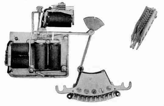
Structure of Line Switch. The details of the parts of a line switch that are individual to the line are shown in Fig. 385, the line and trunk contact bank being shown in the lower portion of this figure and also in a separate view in the detached figure at the right. A detailed group of several such line switches with the oscillating master bar is shown in Fig. 386. This figure shows quite clearly the relative arrangement of the line and trunk contact banks, the plungers for each bank, and the master bar.
Fig. 385. Line Switch View full size illustration.
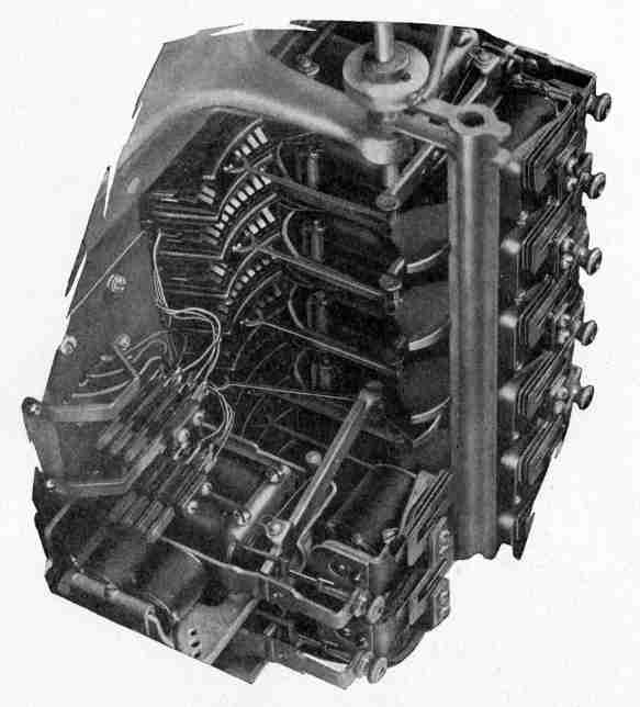
In practice, four groups of twenty-five line switches each are mounted on a single framework and the group of one hundred line switches, together with certain other portions of the apparatus that will be referred to later, form a line-switch unit. A front view of such a unit is shown in Fig. 387. In order to give access to all portions of the wiring and apparatus, the framework supporting each column of fifty line switches is hinged so as to open up the interior of the device as a whole. A line-switch unit thus opened out is shown in Fig. 388.
Fig. 386. Portion of Line-Switch Unit View full size illustration.
Circuit Operation. The mode of operation of the line switch may be best understood in connection with Fig. 389, which shows in a schematic way the parts of a line switch that are individual to a subscriber's line, and also those that are common to a group of fifty or one hundred lines. Those portions of Fig. 389 which are individual to the line are shown below the dotted line extending across the page. The task of understanding the line switch will be made somewhat easier if Figs. 385 and 389 are considered together. The individual parts of the line switch are shown in the same relation to each other in these two figures with the exception that the bank of line and trunk springs in the lower right-hand corner of Fig. 389 have been turned around edgewise so as to make an understanding of their circuit connections possible.
Fig. 387. Line-Switch Unit View full size illustration.
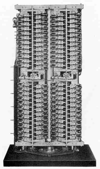
Fig. 388. Line-Switch Unit View full size illustration.
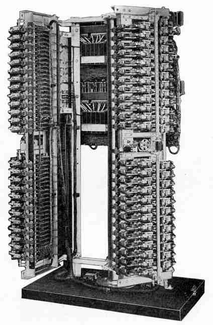
Fig. 389. Circuits of Line-Switch Unit View full size illustration.
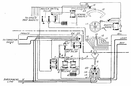
The vertical and rotary sides of the subscriber's line are shown entering at the lower left-hand corner of this figure, and they pass to the springs of the contact bank. Immediately adjacent to these springs are the trunk contacts from which the vertical and the rotary limbs of the first selector trunk proceed. The plunger is indicated at 1, it being in the form of a wheel of insulating material. It is carried on the rod 2 pivoted on a lever 3, which, in turn, is pivoted at 4 in a stationary portion of the framework. A spring 5, secured to the underside of the lever 3 and projecting to the left beyond the pivot 4 of this lever, serves always to press the right-hand portion of the lever 3 forward in such direction as to tend to thrust it into the contact bank. The plunger is normally held out of the contact bank by means of the latch 6 carried on the armature 7 of the trip magnet. When the trip magnet is energized it pulls the armature 7 to the left and thus releases the plunger and allows it to enter the contact bank.
The master bar is shown at 8, and a feather on this bar engages a notch in the segment attached to the rear end of the plunger rod 2. This master bar is common to all of the plunger rods and by its oscillatory movement, under the influence of the master switch, it always keeps all of the idle plunger bars pointed toward the contacts of an idle trunk. As soon, however, as the trip magnet is operated to cause the insertion of a plunger into the contact bank, the feather on the master bar is disengaged by the notch in the segment of the plunger rod, and the plunger rod is, therefore, no longer subject to the oscillating movement of the master bar.
When the release magnet is energized, it attracts its armature 9 and this lifts the armature 7 of the trip magnet so that the latch 6 rides on top of the left-hand end of the lever 3. Then, when the release magnet is de-energized, the spring 5, which was put under tension by the latch, moves the entire structure of levers back to its normal position, withdrawing the plunger from the bank of contacts. The notch on the edge of the segment of the plunger rod, when thus released, will probably not strike the feather on the master bar, and the plunger rod will thus not come under the control of the master bar until the master bar has moved, in its oscillation, so that the feather registers with the notch, after which this bar will move with all the others.
If, while the plunger is waiting to be picked up by the master bar, the same subscriber should call again, his line will be connected with the same trunk as before. There is no danger in this, however, that the trunk will be found busy, because the master bar will not have occupied a position which would make it possible for any of the lines to appropriate this trunk during the intervening time.
Master Switch. Associated with each master bar there is a master switch which determines the position in which the master bar shall stop in order that the idle plungers may be pointed always to the contacts of an idle trunk. The arm 10 of this switch is attached to the master bar and oscillates with it and serves to connect the segment 11 successively with the contacts 12, which are connected respectively to the third, or release wire of each first selector trunk. In the figure the arm 10 is shown resting on the sixth contact of the switch and this sixth contact is connected to a spring 13 in the line-switch contact bank that has not yet been referred to. As soon as the plunger is inserted into the contact bank, the spring 14 will be pressed into engagement with the spring 13, and this spring 14 is connected with the live side of the battery through the release magnet winding.
The contact strip 11 on the master switch is thus connected through the release magnet to the battery and from this current flows through the left-hand winding of the master-switch relay. This energizes this relay and causes the closure of the circuit of the locking magnet which magnet unlocks the master bar to permit its further rotation. The unlocking of the master bar brings the spring 15 into engagement with 16 and thus energizes the master magnet, the armature of which vibrates back and forth after the manner of an electric-bell armature, and steps the wheel 17 around. The wheel 17 is mechanically connected to the master bar so that each complete revolution of the wheel will cause one complete oscillation of the master bar. The master bar will thus be moved so as to cause all the idle plungers to sweep through an arc and this movement will stop as soon as the master-switch arm 10 connects the arc 11 with one of the contacts 12 that is not connected to the live side of the battery through the springs 13 and 14 of some other line switch. It is by this means that the plungers of the line switches are always kept pointing at the contacts of an idle trunk. The way in which this feature has been worked out must demand admiration and accounts for the marvelous quickness of this line switch. The fact that the plungers are pointed in the right direction before the time comes for their use, leaves only the simple thrusting motion of the plunger to accomplish the desired connection immediately upon the initiation of a call by the subscriber.
Locking Segment. It will be understood that the locking segment 18 and the master-switch contact finger 10 are both rigidly connected with the master bar 8 and move with it, the locking segment 18 serving always to determine accurately the angular position at which the master bar and the master-switch arm are brought to rest.
Bridge Cut-Off. One important feature of automatic switching, particularly as exemplified in the system of the Automatic Electric Company, is the disconnection, after its use, of each operating magnet of each piece of apparatus involved in making a connection. Since these operating magnets are always bridged across the line at the time of their operation and then cut off after they have performed their function, this feature may be referred to as the bridge cut-off.
Guarding Functions. Still another feature of importance is the means for guarding a line or a piece of apparatus that has already been appropriated or made busy, so that it will not be appropriated or connected with for use in some other connection. For this latter purpose contacts and wires are associated with each piece of apparatus, which are multipled to similar contacts on other pieces of apparatus in much the same way and for a similar purpose that the test thimbles in a multiple switchboard are multipled together. Such wires and contacts in the Automatic Electric Company's apparatus are called private wires and contacts.
The bridge cut-off and guarding functions are provided for in the line switch by a bridge cut-off relay shown in Fig. 389 and also in Fig. 385, it being the upper one of the individual line relays in each of those figures. This bridge cut-off relay is operated as soon as the plunger of the line is thrust into the bank; the contacts 19 and 20, closed by the plunger, serving to complete the circuit of this relay. To make clear the bridge cut-off feature it will be noted that the trip magnet of a line switch is connected in a circuit traced from the rotary side of the line through the contacts 21 and 22 of the bridge cut-off relay, thence through the coil of the trip magnet to the common wire leading to the spring 23 of the master-bar locking device and thence to the live side of the battery. Obviously, therefore, as soon as the bridge cut-off relay operates, the trip magnet becomes inoperative and can cause no further action of the line switch because its circuit is broken between the springs 21 and 22.
The private or guarding feature is taken care of by the action of the plunger in closing contacts 19 and 20, since the private wire leading to the bridge cut-off relay is, as has already been stated, connected to ground when these contacts are closed. This private wire leads off and is multipled to the private contacts on all the connectors that have the ability to reach this line, and the fact that this wire is grounded by the line switch as soon as it becomes busy, establishes such conditions at all of the connectors that they will refuse to connect with this line as long as it is busy, in a way that will be pointed out later on.
Relation of Line Switch and Connectors. The vertical and rotary wires of the subscriber's line are shown leading off to the connector banks at the left-hand side of Fig. 389, and one side of this connection passes through the contacts 24 and 25 of the bridge cut-off relay on the line switch. It is through this path that a connection from some other line through a connector to this line is established and it is seen that this path is held open until the bridge cut-off relay of the line switch is operated. For such a connection to this line the bridge cut-off relay of the line switch is operated over the private wire leading from the connector, and the operation of the bridge cut-off relay at this time serves to render inoperative the line switch, so that it will not perform its usual functions should the called subscriber start to make a call after his line had been seized.
Summary of Line-Switch Operation. To summarize the operation of a line switch when a call is originated on its line, the first movement of the calling subscriber's dial will ground the rotary side of the line and operate the trip magnet. This will cause the plunger to be inserted into the bank, and thus extend the line to the first selector trunk through the closing of the right-hand set of springs shown in the lower right-hand corner of Fig. 389. The insertion of the plunger will also connect the battery through the left-hand winding of the master-switch relay and, by the sequence of operations which follows, cause the master bar to move all of the idle plungers so as to again point them to an idle trunk. The closure of contacts 19 and 20 by the plunger causes the operation of the bridge cut-off relay which opens the circuit of the trip magnet, rendering it inoperative; and also establishes ground potential on all the private wire contacts of that line in the banks of the connectors, so as to guard the line and its associated apparatus against intrusion by others. The line is cut through, therefore, to a first selector and all of the line-switch apparatus is completely cut off from the talking circuit.
It must be remembered that all of the actions of the line switch, which it has taken so long to describe, occur practically instantaneously and as a result of the first part of the first movement of the subscriber's dial. The line switch has done its work and "gone out of business" before the selective impulses of the first digit begin to take place.
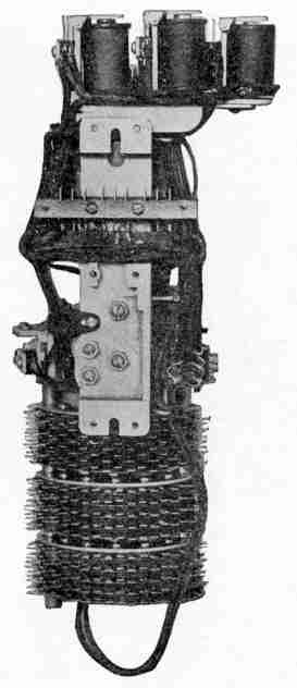
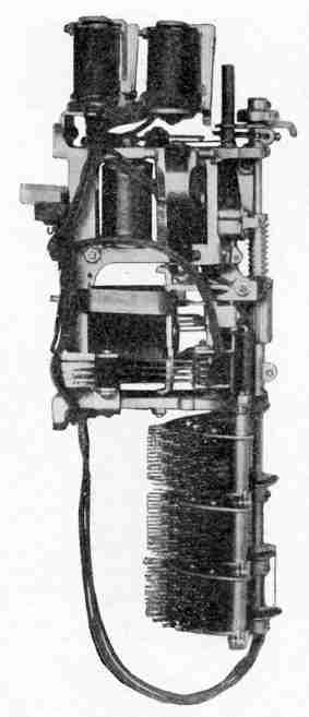
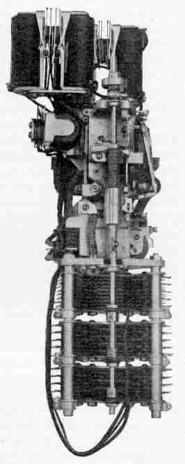
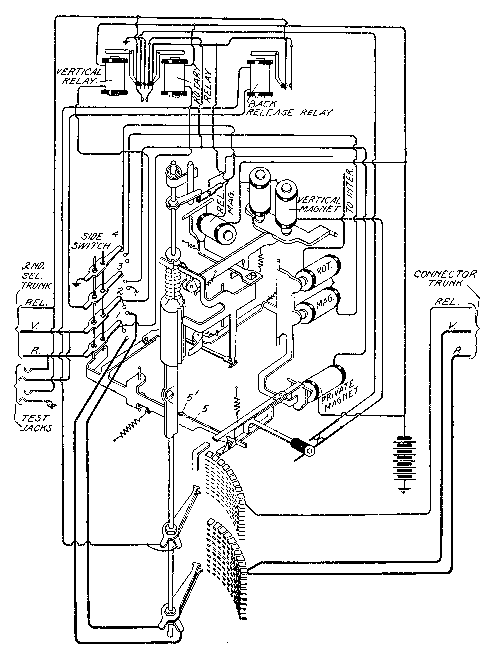
Selecting Switches. The first selector is now in control of the calling subscriber. The circuits and elements of the first selector switch are shown in Fig. 390. The general mechanical structure of the first selectors, second selectors, and connectors, is the same and may be referred to briefly here. Fig. 391 shows a rear view of a first selector; Fig. 392, a side view of a second selector; and Fig. 393, a front view of a connector. The arrangement of the vertical and rotary magnets, of the selector shafts, and of the contact banks are identical in all three of these pieces of apparatus and all these switches work on the "up-and-around principle" referred to in connection with Fig. 380. It is thought that with the general structure shown in Figs. 391, 392, and 393 in mind, the actual operation may be understood much more readily from Fig. 390.
Four magnets—the vertical, the rotary, the private, and the release—produce the switching movements of the machine. These magnets are controlled by various combinations brought upon the circuits by three relays—the vertical, the rotary, and the back release. The fourth relay shown, called the off-normal, is purely for signaling purposes, as will be described.
Side Switch. Another important element of the selecting switches is the so-called side switch which might better be called a pilot switch—but we are not responsible for its name. This side switch has for its function the changing of the control of the subscriber's line to successive portions of the selector mechanism, rendering inoperative those portions that have already performed their functions and that, therefore, are no longer needed. This switch may be seen best in Fig. 392 just above the upper bank of contacts. It is shown in Fig. 390 greatly distorted mechanically so as to better illustrate its electrical functions.
Fig. 390. Circuits of First Selector View full size illustration.
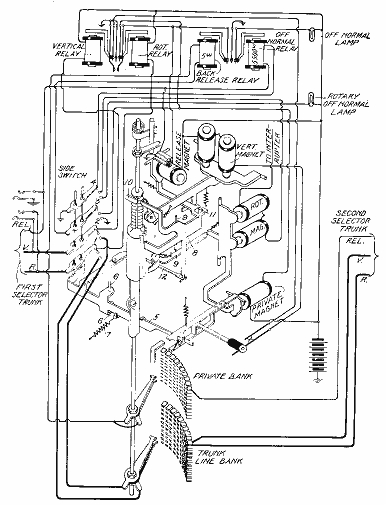
The contact levers 1, 2, 3, and 4 of the side switch are carried upon the arm 5 which is pivoted at 6. All of these contact levers, therefore, move about 6 as an axis. The side switch has three positions and it is shown, in Fig. 390, in the first one of these. When the private magnet armature is attracted and released once, the escapement carried by it permits the spring 7 to move the arm 5 so as to bring the wipers of the side switch into its second position; the second pulling up and release of the private magnet armature will cause the movement of the side switch wipers into the third position. It is to be noted that the escapement which releases the side switch arm may be moved either by the private or by the rotary magnet, since the armature of the latter has a finger which engages the private magnet armature.
Fig. 391. Rear View of First Selector View full size illustration.
Functions of Side Switch. The functions of the side switch may be briefly outlined in connection with the first selector, as an example. In the first position it extends the control of the subscriber's signal transmitter through the first selector trunk and line relays to the vertical and private magnets so that these magnets will be responsive to the selecting impulses corresponding to the first digit. In its second position it brings about such a condition of affairs that the rotary magnet will be brought into play and automatically move the wipers over the bank contacts in search of an idle trunk. In its third position, both the vertical and rotary relays are cut off and the line is cut straight through to the second selector trunk, and only those parts of the first selector apparatus are left in an operative state which have to do with the private or guarding circuits and with the release. Similar functions are performed by the side switch in connection with the other selecting switches.
Fig. 392. Side View of Second Selector View full size illustration.
Release Mechanism. Another one of the features of the switch that needs to be considered before a detailed understanding of its operation may be had, is the mechanical relation of the holding and the release dog. This dog is shown at 8 and, in the language of the art, is called the double dog. As will be seen, it has two retaining fingers, one adapted to engage the vertical ratchet and the other, the rotary ratchet on the selector shaft. This double dog is pivoted at 9 and is interlinked in a peculiar way with the armature of the vertical magnet, the armature of the release magnet, and the arm of the side switch. The function of this double dog is to hold the shaft in whatever vertical position it is moved by the vertical magnet and then, when the rotary magnet begins to operate, to hold the shaft in its proper angular position. It will be noted that the fixed dog 10 is ineffective when the shaft is in its normal angular position. But as soon as the shaft is rotated, this fixed dog 10 becomes the real holding pawl so far as the vertical movement is concerned. The double dog 8 is normally held out of engagement with the vertical and the rotary ratchets by virtue of the link connection, shown at 11, between the release magnet armature and the rear end of the double dog. On the previous release of the switch the attraction of the release magnet armature permitted the link 11 to hook over the end of the dog 8 and thus, on its return movement, to pull this dog out of engagement with its ratchets. This movement also resulted in pushing on the link 12 which is pivoted to the side switch arm 5, and thus the return movement of the release magnet is made to restore the side switch to its normal position. In order that the double dog may be made effective when it is required, and in order that the side switch may be free to move under the influence of the private magnet, the double dog is released from its connection with the release magnet armature by the first movement of the vertical magnet in a manner which is clear from the drawing.
First Selector Operation. In discussing the details of operation of the various selectors it will be found convenient to divide the discussion according to the position of the side switch. This will bring about a logical arrangement because it is really the side switch which determines by its position the sequence of operation.
Fig. 393. Front View of Connector View full size illustration.
First Position of Side Switch. This is the position shown in Fig. 390, and is the normal position. The vertical and the rotary lines extending from the calling subscriber are continued by the levers 1 and 2 of the side switch through the vertical and the rotary relay coils, respectively, to the live side of battery. The lever 4 of the side switch in this position connects to ground the circuit leading from the line switch through the release trunk, and the winding of the off-normal relay. This winding is thus put in series with the release magnet of the line switch, but on account of high resistance of the off-normal relay no operation of the release magnet is caused. This will, however, permit such current to flow through the release circuit as will energize the sensitive off-normal relay and cause it to attract its armature and light the off-normal lamp. If this lamp remains lighted more than a brief period of time, it will attract notice and will indicate that the corresponding selector has been appropriated by a line switch and that for some reason the selector has gone no further. This lamp, therefore, is an aid in preventing the continuance of this abnormal condition.
The first thing that happens after the line switch has connected the calling subscriber with the first selector is a succession of impulses over the vertical side of the line, this being the set of impulses corresponding in number to the thousands digit or to the office, if there is more than one. It will be understood that here we are considering a single office of ten-thousand-line capacity or thereabouts, and that, therefore, this first set of impulses corresponds to the thousands digit in the called subscriber's line. Each one of these impulses will flow from the battery through the vertical relay and each movement of this relay armature will close the circuit of the vertical magnet and cause the shaft of the selector to be stepped up to the proper level. Immediately following the first series of selecting impulses from the subscriber's station, a single impulse follows over the rotary side of the line. This gives the rotary relay armature one impulse and this in turn closes the circuit of the private magnet once. The single movement of the private magnet armature allows the escapement finger on the arm 5 to move one step and this brings the side switch contacts into the second position.
Second Position of Side Switch. In this position lever 4 of the side switch places a ground on the wire leading through the rotary magnet to a source of interrupted battery current. The impulses which thus flow through the rotary magnet occur at a frequency dependent upon the battery interrupter and this is at a rate of approximately fifteen impulses per second. The rotary magnet will step the selector shaft rapidly around until something occurs to stop these impulses. This something is the finding by the private wiper of an ungrounded private contact in the bank, since all of the contacts corresponding to busy trunks are grounded, as will be explained.
The action of the private magnet enters into this operation in the following way: A circuit may be traced from the battery through the private magnet to the third side switch wiper when in its second position, thence through the back release relay to the private wiper. If the wiper is at the time on the private bank contact of a busy trunk, it will find that contact grounded and the private magnet will be energized. The energizing of this magnet will not, however, cause the release of the side switch. It must be energized and de-energized. The private magnet armature will, therefore, be operated by the finger of the rotary magnet armature on the first rotary step. The private magnet will be energized and hold its armature operated if the private wiper finds a ground on the first bank contact and will stay energized as long as the private wiper is passing over private contacts of busy trunks. Its armature will not be allowed to fall back during the passage of the wiper from one trunk to another, because during that interval the finger of the rotary magnet will hold it operated. As soon, however, as the private wiper reaches the private bank contact of an idle trunk, no ground will be found and the circuit of the private magnet will be left open. When the impulse through the rotary magnet ceases, the private magnet armature will fall back and the side switch will be released to its third position.
Third Position of Side Switch. The first thing to be noted in this position is that the calling line is cut straight through to the second selector trunk, the connection being clean with no magnets bridged across or tapped off. The third wiper of the side switch, when in its third position, is grounded and this connects the release wire of the second selector trunk, on which the switch wipers rest, through the private wiper, the winding of the back release magnet, and the third wiper of the side switch to ground. This establishes a path for the subsequent release current through the back release magnet; and, of equal importance, it places a ground on the private bank contact of that trunk so that the private wiper of any other switch will be prevented from stopping on the contacts of this trunk in the same manner that the wiper of this switch was prevented from stopping on other trunks that were already in use.
The fourth lever on the side switch, when in its third position, serves merely to close the circuit of the rotary off-normal lamp. This lamp is for the purpose of calling attention to any first selector switch that has been brought into connection with some second selector trunk and which, for some reason, has failed in its release. These off-normal lamps are so arranged that they may be switched off manually to avoid burning them during the hours of heaviest traffic. At night they afford a ready means of testing for switches that have been left off-normal, since the manual switches controlling these lamps may then be closed, and any lamps which burn will show that the switches corresponding to them are off-normal. Simple tests then suffice to show whether they are properly or improperly in their off-normal position.
Release of the First Selector. As will be shown later, the normal way of releasing the switches is from the connector back over the release wire. It is sufficient to say at this point that when the proper time for release comes, an impulse of current will come back over the second selector trunk release wire through the private wiper, to the back release relay magnet, and thence to ground through the third wiper of the side switch which is in its third position. It may be asked why the back release magnet was not energized during the previous operations described, when current passed through it. The reason for this is that in those previous operations the private magnet was always included in series in the circuit and on account of the high resistance of the private magnet, sufficient current did not pass through the back release magnet to energize it.
When the back release relay is energized, it closes the circuit of the release magnet and thus, through the link 11, draws the double dog away from its engagement with the shaft ratchets and at the same time, through the link 12, restores the side switch to its normal position. Whenever the release magnet is operated it acts as a relay to close a pair of contacts associated with it and thus to momentarily ground the release wire of the first selector trunk extending back to the line switch. Referring to Fig. 389, it will be seen that this path leads through the contacts 13 and 14 and the release magnet to the battery. It is by this means that the line switch is released, the release impulse being relayed back from the first selector.
Second Selector Operation. For the purpose of considering the action of the second selector, we will go back to the point where the first selector had connected with a second selector trunk and where its side switch had moved into its third position. In this condition, it will be remembered, the trunk line was cut through to a second selector trunk and all first selector apparatus cleared from the talking circuit.
The second selector chosen is one corresponding to the thousands group as determined by the first digit of the called subscriber's number. The circuits of a second selector are shown in Fig. 394 and it must be borne in mind that the mechanical arrangements for producing the vertical and the rotary movement of the shaft and for operating the side switch are practically the same as those of the first selector. As in the first selector, the sequence of operation is controlled by the successive positions of the side switch, the first position permitting the selection of the hundreds corresponding to the vertical impulses, the second position allowing the selector to search for an idle trunk in that hundred, and the third position cutting the trunk through and clearing the circuit of obstructing apparatus.
First Position of Side Switch. The first thing that happens when the subscriber begins to move his dial in the transmission of the second series of selecting impulses is the sending of a preliminary impulse over the rotary side of the line. This, in the case of the second selector, energizes the rotary relay which, in turn, energizes the private magnet; but the private magnet in the case of the second selector can do nothing toward the release of the side switch because the projection 5', on the side switch arm 5, meets a projection on the rear of the selector shaft which thus prevents the movement of the side switch arm 5 until the selector shaft has been moved out of its normal position.
Immediately after the establishment of the connection to the selector, the second set of selecting impulses comes in over the vertical wire from the subscriber's station. These impulses, corresponding in number to the hundreds digit, will energize the vertical relay and cause it, in turn, to energize the vertical magnet, stepping up the selector shaft to the level corresponding to the hundred sought. The single rotary impulse, which follows just before the subscriber's dial reaches its normal position, will energize the rotary relay of the second selector. This, in turn, energizes the private magnet which makes a single movement of its armature and allows the escapement finger on the side switch arm to move one step and bring the side switch contacts into the second position.
Fig. 394. Circuits of Second Selector View full size illustration.
Second Position of Side Switch. No detailed discussion of this is necessary, since, with the side switch in its second position, the actions which occur in causing the wipers of the second selector to seek and connect with an idle trunk line, are exactly the same as in the case of the first selector. When the second selector wipers finally reach a resting place on the bank contacts, the private magnet armature, operated during the hunting process, is released and the side switch is thus shifted into the third position.
Third Position of Side Switch. The moving of the side switch into its final position brings about the same state of affairs with respect to the second selector that already exists with respect to the first selector. The trunk line is cut straight through and all bridge circuits or by-paths from it are cut off. The same guarding conditions are established to prevent other lines or other pieces of apparatus from making connections that will interfere with the one being established, and the same provisions are made for working the back release when the proper impulse comes from the connector, and for passing this back release impulse on to the first selector in the same way that the first selector passes it on to the line switch. The line of the calling subscriber has now been extended to a connector, and that connector is one of a group—usually ten—which alone has the ability to reach the particular hundred lines containing the line of the desired subscriber. The selection has, therefore, been narrowed down from one in ten thousand to one in one hundred.
The Connector—Its Functions. It has already been stated that the connector is of the same general type of apparatus as the first and the second selectors. Unlike the first and the second selectors, however, the connector is required to make a double selection under the guidance of the subscriber. The first selector makes a single selection of a group under the guidance of the subscriber and then an automatic selection in that group not controlled by the subscriber. So it is with the second selector. The connector, however, makes a selection of a group of ten under the guidance of the subscriber and then, again under the guidance of the subscriber, it picks out a particular one of that group.
The connector also has other functions in relation to the ringing of the called subscriber and the giving of a busy signal to the calling subscriber in case the line wanted is found busy. It has still other functions in that the talking current, which is finally supplied to connected subscribers, is supplied through paths furnished by it.
Location of the Connectors. Connectors are the only ones of the selecting switches that are in any sense individual to the subscribers' lines. None of them is individual to a subscriber's line, but it may be said that a group of ten connectors is individual to a group of one hundred subscribers' lines. Since each group of one hundred lines has a group of connectors of its own and since each one hundred lines also has a line-switch unit of its own, and since the lines of this group must be multipled through the bank contacts of the connectors of this individual group and through the bank contacts of the line switches of this particular unit, it follows that on account of the wiring problems involved there is good reason for mounting the connectors in close proximity to the line switches representing the same group of lines. Some help in the grasping of this thought may result if it be remembered that the line switch is, so to speak, the point of entry of a call and that the connector is the point of exit, and, in order to reduce the amount of wiring and to economize space, the point of exit and the point of entry are made as close together as possible.
The relative locations and grouping of the line switches and connectors are clearly shown in Fig. 395, which is a rear view of the same line-switch unit that was illustrated in Figs. 387 and 388.
Operation of the Connector. The circuits of the connector are shown in Fig. 396. In addition to the features that have been pointed out in the first and the second selectors, all of which are to be found, with some modifications, perhaps, in the connector, there must be considered the features in the connector of busy-signal operation, of ringing the called subscriber, of battery supply to both subscribers, and of the trunk release operation. These may be best understood by tracing through the operations of the connector from the time it is picked up by a second selector until the connection is finally completed, or until the busy signal has been given in case completion was found impossible. As in the first and the second selectors, the sequence of operations is determined by the position of the side switch.
Fig. 395. Connector Side of Line-Switch Unit View full size illustration.
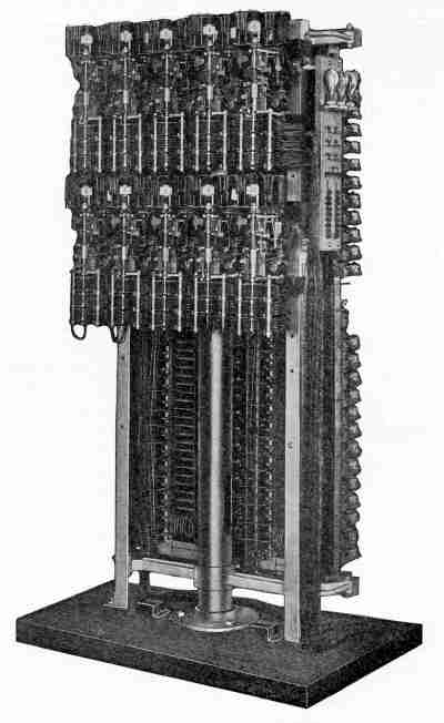
Fig. 396. Circuits of Connector View full size illustration.
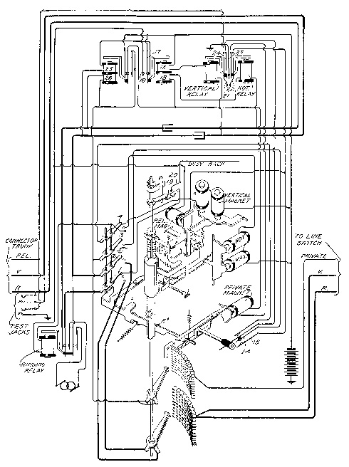
First Position of Side Switch. The connector in a ten-thousand-line system is the recipient of the impulses resulting from the third and fourth movements of the subscriber's dial. Considering the third movement of the subscriber's dial, the first impulse resulting from it comes over the rotary side of the line and results in the rotary relay attracting its armature once. This results in a single impulse through the private magnet which, however, does nothing because the projection 5' strikes against a projection on the selector shaft. These two projections interfere only when the selector shaft is in its normal position. Then follows the series of impulses from the subscriber's station corresponding to the tens digit in the called subscriber's number. These pass over the vertical side of the line and through the vertical relay, energizing that relay a corresponding number of times.
The vertical magnet, as in the case of the first and the second selectors, is included in the circuit controlled by the vertical relay and this results in the connector shaft being stepped up to the level corresponding to the particular tens group containing the called subscriber's number. It will be noted that the impulses from the vertical side of the line, which cause this selection, pass through one winding 13 of the calling battery supply relay. This relay is operated by these vertical selecting impulses, but in this position of the side switch the closure of its local circuits accomplishes nothing.
Immediately after the tens group of selecting impulses over the vertical side of the line, there follows a single rotary impulse from the subscriber's station which, as in the case of the first and the second selectors, energizes the rotary relay and causes it to give one impulse to the private magnet. This impulse is now able, since the shaft has moved from its normal position, to release the side switch arm one notch, and the side switch, therefore, moves into its second position.
Second Position of Side Switch. It is principally in this second position of the side switch that the connector selecting function differs from that of the first and the second selector. There is no trunk to be hunted, but rather the rotary movement of the connector wipers must be made in response to the impulses, from the subscriber's station, which correspond to the units digit in the selected number. The first impulse corresponding to the fourth movement of the subscriber's dial is a rotary one, and, as usual, it passes through the rotary relay winding and this, in turn, gives an impulse to the private magnet. The private magnet at this time has already released the side switch arm to its second position, but it is unable to release it further because of a feather on the wiper shaft—which projects just far enough to engage the lug 5', when the shaft is in its normal angular position—thus preventing the side switch arm from moving farther than its second position.
Then follows over the vertical side of the line the last set of selecting impulses corresponding to the units digit. This, as before, energizes the vertical relay, but in the second position of the side switch, it is to be noted, that the vertical relay no longer controls the vertical magnet; the side switch has shifted the control of the vertical relay to the rotary magnet. The rotary magnet is, therefore, energized a number of times corresponding to the last digit in the called number and the wipers of the connectors are thus brought to the contacts of the line sought—their final goal. At this point many things may happen, and the things that do happen depend on whether the called subscriber's line is idle or busy.
Called-Line Busy:—It will first be assumed that the called line is busy. The testing operation at the connectors occurs in the second position of the side switch. If the called line is busy, it will be either because it is connected to by some other connector or because it has itself made a call. In the former case the private contacts of that line in the banks of all the connectors serving that hundreds group of lines will be grounded through the private wiper of some other connector. That this is so, may be seen by tracing the circuit from the private wiper on the shaft to the third side switch wiper which is grounded in the third position; the other connector that has already engaged the line will, of course, have its side switch in its final, or third position. Again, if the line called is busy, because a call has already been made from this line to some other line, the private contacts on the connectors corresponding to the line will be grounded, as will be seen by tracing from the private bank contacts, which are shown in Fig. 396, through the private wire to the line switch, which is shown in Fig. 389, and from thence to ground through the springs 19 and 20, which are brought together when the line switch is operated.
In any event, therefore, the determining condition of a busy line is that its private bank contacts on all connectors of its group shall be grounded. Under the present assumed condition, therefore, the connector wipers, which have been brought to the bank contacts of the desired line, will find a ground at the private bank contact. The connector shaft stops for an instant on the contacts of this busy line and immediately there follows over the rotary side of the line the inevitable single rotary impulse. This energizes the rotary relay and this, as usual, energizes the private magnet. Remembering now that the connector side switch is in its second position and that the private wiper of the connector has found a ground, we may trace back from the private wiper through the third side switch wiper to its second contact; thence through the contact springs 14 and 15, closed by the private magnet; thence through the release magnet; thence through the contact springs 16 and 17 of the calling battery supply relay to the live side of the battery. This calling battery supply relay will, at this time, have its core energized because the coil 18 is in series with the rotary relay coil which, as just stated, was energized by the last rotary impulse. This series of operations has led to the energizing of the release magnet, and, as a result, the double dog of the connector is pulled out of the connector shaft ratchets and the shaft and the side switch are restored to their normal position.
Busy-Back Signal:—The connector has dropped back to normal in all respects. The calling subscriber, not knowing this, presses his ringing button. This grounds the vertical side of the line at his station and operates the vertical relay at the connector. This steps the shaft of the connector up one step and causes the closure of the contacts 19 and 20 at the top of the connector shaft. This establishes a connection to a circuit carrying periodically interrupted battery current on which an inductive hum is placed. This circuit may be traced from this source through the springs 20 and 19 to the first wiper of the side switch, thence through the normally closed contacts of the ringing relay to the rotary side of the line, and the varying potential to which this path is subjected produces an inductive flow back to the calling subscriber's telephone, and gives him the necessary signal which consists of a hum or buzzing noise with which all users of automatic systems soon become familiar.
Release on Busy Connection:—The connector, since its last release, has been stepped up one notch and must again be released. When the subscriber hangs up his receiver after receiving the busy signal, he grounds both sides of his line momentarily by the action of the springs 21, 22, and 23 of Fig. 384. This operates the rotary and the vertical relays on the connector simultaneously and brings together for the first time the springs 21 and 22 of Fig. 396. This establishes a connection from the battery through the springs 16 and 17 on the calling battery supply relay, thence through the release magnet of the connector, thence through the springs 22 and 21 of the vertical and the rotary relay, thence through the release trunk back to the second selector. From here the circuit passes through the private wiper of that selector and the back release relay to ground through the third side switch wiper which is in the third position. Considering this circuit in respect to its action on the connector it is obvious that it energizes the release magnet on the connector which restores the connector to normal as before. At the second selector this circuit passed through the back release relay, which closed a circuit through the release magnet and through the back release relay contacts, thence back over the second selector release trunk to the back release relay of the first selector, and through the third wiper of the side switch on that selector to ground, since that side switch also is in its third position. The current through this circuit energizes the release magnet of the second selector and restores it to its normal position and also energizes the back release relay of the first selector. This, in turn, closes the circuit from the battery through the release magnet of the first selector and contacts of the back release relay to ground. This works the release magnet of the first selector and restores that selector to normal. The contacts on the first selector release magnet, shown in Fig. 390, are closed by the action of the release magnet and this closes the path from ground back through the first selector release wire, and through the contacts 13 and 14 of the line switch, through the line switch release magnet to battery, and this restores the line switch to normal.
The reason for the term back release will now be apparent. The release operation at the connector is relayed back to the second selector; that of the second selector back to the first selector; and that of the first selector back to the line switch. Until this plan was adopted, the release magnet of each selector and connector involved in a connection was left bridged across the talking circuit so as to be available for release; and it sometimes occurred that a first selector would be released before a second selector or connector, which latter switches would thus be left off-normal until rescued by an attendant. The back release plan makes it impossible for the connection necessary for the release of a switch to be torn down until the release is actually accomplished.
Called Line Found Idle:—It will be remembered that, before the digression necessary to trace through the operations occurring upon the finding of a busy line, the connector wipers had been brought, by the influence of the calling subscriber's impulses, into engagement with the contacts of the desired line; that the connector side switch was in its second position; and that the final rotary impulse following the last series of selecting impulses had not been sent. The condition now to be assumed is that the called subscriber's line is free and the private wiper, therefore, has found and rests on an ungrounded private bank contact. The final rotary impulse which immediately follows will operate the rotary relay and this, in turn, will operate the private magnet. This happened under the assumed condition that the line was busy, but in that case the release magnet was also operated at the same time and restored all conditions to normal. Under the present condition the operation of the private magnet will perform its usual function and move the side switch of the connector into its third position.
Third Position of Side Switch. When the side switch of the connector moves to its third position, it, as usual, cuts the talking circuit straight through from the vertical and the rotary sides of the trunk leading from the previous selector to the outgoing terminal of the subscriber's line, which may be traced upon Fig. 396 back through the line switch, shown in Fig. 389. Several things are to be noted about the talking circuit so established: First, the inclusion of the condensers in the vertical and the rotary sides of the connector circuit. The purpose of this will be referred to later. Second, the inclusion in this circuit at the connector of a pair of normally closed contacts in the ringing relay. It may be said in passing that the ringing relay corresponds exactly in function to a ringing key in a manual switchboard. Third, the talking circuit leading from the connector to the called subscriber's line passes on one side through the springs 24 and 25 of the bridge cut-off relay of the line switch, which is shown in Fig. 389. These springs are normally open and would prevent the completion of the talking circuit but for the fact that the bridge cut-off relay of the line switch is energized over the private wire leading to the connector bank and then through the connector wiper to the third side switch wiper which, at this time, is in its third position. The talking circuit is thus complete. The operation of this bridge cut-off relay on the line switch has not only completed the talking circuit but it has also opened the circuit of the trip magnet of the line switch so as to prevent the operation of the trip magnet by the subscriber on that line in case he should attempt to make a call during the interval between the time when his line was connected with by the connector and the time when he answers the call.
The third wiper of the connector side switch when moved into its third position, puts the ground on all of the private bank contacts of the line chosen and thus guards that line against connection by others, as already described. It also operates the bridge cut-off relay of the line switch as just mentioned.
The fourth wiper of the side switch, when moved into its third position, establishes such a connection as will place the ringing relay under the control of the vertical relay. This may be seen by tracing from ground to the vertical relay springs 23 and 24, thence through the normally closed upper pair of contacts on the private magnet, thence through the fourth wiper on the side switch to its third contact, thence through the ringing relay magnet, and through the springs 16 and 17 of the calling battery supply relay and to battery. The calling battery supply relay winding being in series with the vertical relay winding, the two operate together and close the two normally open points in the ringing relay circuit. This ringing relay acts as an ordinary ringing key and connects the generator to the called subscriber's line in an obvious manner, at the same time opening the talking circuit back of the ringing relay in order to prevent the ringing current chattering the relays in the circuit back of it. All that remains now is for the called subscriber to respond. When he does he closes the metallic circuit of the line through his talking apparatus.
Battery Supply to Connected Subscriber. Throughout the whole process of building up a connection, it will be remembered that both sides of the calling line are connected through the respective vertical and rotary relays involved in building up the connection with the live side of the battery. At the time when the connection is finally established and the called subscriber rung, both sides of the calling line are connected through various relay windings to the live side of the battery. Such a condition leaves both sides of the line at the same potential and, therefore, there is no tendency for current to flow through the calling subscriber's talking apparatus, even though it is connected across the circuit of the line. It remains, therefore, to be seen how these conditions are so changed after the building up of a connection as to supply the calling subscriber with talking current.
The calling subscriber can get no current until the called subscriber responds. When the connection is first made with the called subscriber's line, battery connection to his line is made from the live side of battery through the normally closed contacts of the calling battery supply relay, thence through the winding 25 of the called battery supply relay to the vertical side of the called line. The grounded side of the battery is connected to the rotary side of his line through the third wiper of the connector and the coil 26 of the called battery supply relay. As a result, this subscriber receives proper talking current through the coils 25 and 26, and this relay is operated by the flow of this current. The operation of this called battery supply relay merely shifts the connection of the rotary side of the calling subscriber's line from its normal battery connection, to ground, and thus the battery is placed straight across the calling subscriber's line so as to supply talking current. This supply circuit to the calling subscriber may be traced from the live side of the battery through the winding 13 of the calling battery supply relay and the winding of the vertical relay to the vertical side of the line, and from the grounded side of battery through the third side switch wiper in its third position to the now closed pair of contacts in the called battery supply relay through the coil 18 of the calling battery supply relay and the coil of the rotary relay to the rotary side of the line.
It will be noted that the system of battery supply is that of the standard condenser and retardation coil scheme largely employed in manual practice; and that aside from the coils through which the battery current is supplied to the connected subscribers, there are no taps from, or bridges across, the two sides of the talking circuit.
Release after Conversation. It remains now only to secure the disconnection of the subscribers after they are through talking. When the calling subscriber hangs up, the whole disconnection is brought about, all of the apparatus, including connector, selectors, and line switch, returning to normal. This is done by the back release system and is accomplished in almost the same way as has already been described in connection with the disconnect after an unsuccessful call. There is this difference, however: after an unsuccessful call when the line called for was found busy, the release was made while the connector side switch was in its normal position. In the present case, the release must be made with the connector side switch in its third position and with the talking battery bridged across the metallic circuit rather than connected between each limb of the line and ground. It must be remembered that the calling battery supply relay, while traversed by current during the conversation, is not magnetically energized because, with the current flowing through the metallic circuit of the line, the two windings exert a differential effect. As soon, however, as the calling subscriber hangs up his receiver, this differential action ceases, due to the grounding of both sides of the line at the subscriber's station. This relay, therefore, operates and cuts off battery from the called battery supply relay and this, in turn, releases its armature and thus changes the connection of the rotary side of the calling line from ground to live side of the battery. The normal condition of the battery connection now being restored, both the vertical and the rotary relays at the connector become operated, due to the ground on both sides of the line at the subscriber's station, and this, as we have seen, is the condition which brings about the operation of the connector release magnet, and the relaying back of the disconnect impulse successively through the selectors to the line switch.
Multi-Office System. In exchanges involving more than one office, the same general principles and mode of operation already outlined apply. If the total number of subscribers in the multi-office exchange is to be less than ten thousand, then four digit numbers suffice, and the first movement of the dial may be made to select the office into which the connection is to go, the subscribers' lines being so numbered with respect to the offices that each office will contain only certain thousands. The choosing of the thousand by the calling subscriber, therefore, takes care in itself of the choice of offices. Where, however, a multi-office exchange is to provide for connections among a greater number of lines than ten thousand and less than one hundred thousand, then it will take five movements of the dial to make the selection—the five movements corresponding either to the five digits in a number or to the name of an office, as indicated on the dial, and the four digits of a smaller number. The lines may all carry five digit numbers or, what is considered better practice, may be designated by an office name followed by a four digit number. In this latter case the numbers of the subscribers' lines will in each case be contained in one or more of the tens of thousands groups, no number having more than four digits. And the first movement of the dial, whether the name or number plan be adopted, will select an office; or, looking at it another way, will select a group of ten thousand and this being done, the next four successive movements of the dial will select the numbers in that ten thousand in just the some way that has been already described.
Certain difficulties arise, however, in multi-office working due to the fact that the three-wire trunks between offices would in most cases be objectionable. As long as the trunks extend between the various groups of apparatus in the same office, it is cheaper to provide three wires for each of them than it is to make any additional complication in the apparatus. Where the trunking is done between offices, however, the system may be so modified as to work over two wire inter-office trunks.
The Trunk Repeater. The purpose of the trunk repeater is to enable the inter-office trunking to be done over two wires. It may be said that the trunk repeater is a device placed in the outgoing trunk circuit at the office in which a call originates, which will do over the two wires of the trunk leading from it to the distant office just the same thing that the subscriber's signal transmitter does over the two wires of the subscriber's lines. It has certain other functions in regard to feeding the battery for talking purposes back to the calling subscriber's line, taking the place in this respect of the calling battery feed relay in the connector in a single office exchange.