TRANSACTIONS (continued 2)
Reading edition
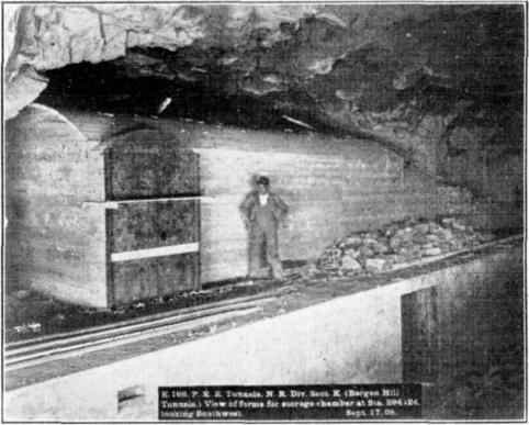
Fig. 2. K 166. P.R.R. Tunnels, N. R. Div. Sect. K. (Bergen Hill Tunnels.) View of forms for storage chamber at Sta. 294+24, looking Southward. Sept. 17, 08.
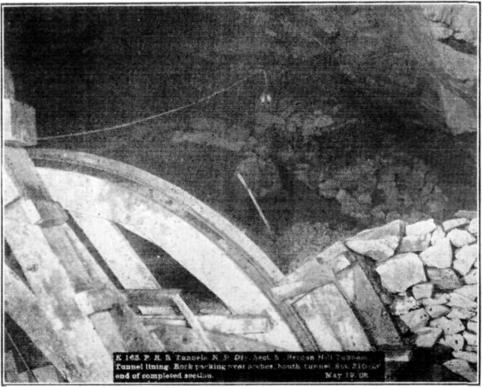
Fig. 3. K 163. P.R.R. Tunnels, N. R. Div. Sect. K. (Bergen Hill Tunnels.) Tunnel lining. Rock packing over arches, South tunnel Sta. ???+?? end of completed section. May 19, 08.
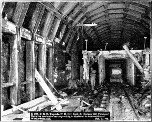
Fig. 4. K 168. P.R.R. Tunnels, N. R. Div. Sect. K. (Bergen Hill Tunnels.) Showing method of waterproofing in timbered tunnel section at Weehawken end. Oct. 21, 08.
A gang of four rough carpenters and a foreman was employed on the day shift; they moved and set the bench-wall forms or sand-wall forms, as the case might be, and moved the traveling gantry into position. This was done in the afternoon, and required about 3 hours. They also took out, cleaned, repaired, and set all ditch forms, all passenger forms, circuit-breaker forms, and did all other repair work. The ladder forms, the refuge-niche forms, and overhead conductor
In concreting the bench-walls, the concrete was first placed on the side containing the single conduit until it reached the top of the four tiers laid, then the concrete gang was turned over to the side with the 4-way conduits while four more tiers of single conduits were laid, the work thus progressing, the conduits being laid on one side while concrete was placed on the other. On the side of the 4-way conduits the concrete was built in two layers while that on the side of the single ducts was built in three; the interval between the different layers was not sufficiently long to prevent a complete bond being obtained, and there were only one or two instances where there was any mark on the face to indicate a break.
After the work had been in progress some time, it was found to be quite feasible to build all the 4-way conduits at night and half the single conduits, that is, 6 ducts high, as the mandrels proved amply sufficient to hold them in place; in fact, had it been necessary, the writer has no doubt that all the ducts might have been laid and held in place with very little extra precaution, by the use of the expanding mandrels, as described under the head of conduit laying. A V-shaped joint about ½ in. deep was made between each section of bench-wall so that the expansion cracks would follow this joint rather than show irregularly on the face. These joints divided the face into the even 25-ft. panels, and were very effectual in concealing what few cracks there were.
After the construction of the sand-walls was discontinued, the space behind the bench-walls, between the neat line and the rock, was filled with rock packing, which was generally built, part way up at least, as a dry wall ahead of the construction of the bench-wall, or it was put in place simultaneously with the concrete, care being taken to keep it as free as possible for the drainage of any water there might be. Toward the latter part of the work, owing to the difficulty of getting sufficient rock packing during the day, a rough back form
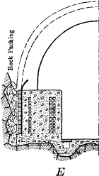
In the sections where water-proofing was required, where no sand-wall was built, the rock was taken out for 2 ft. outside the neat line, if the excavation was not already that far out (at the expense of the contractors, who preferred to do this rather than build the sand-walls for the short sections required), so that there would be sufficient room for placing the water-proofing on the back of the bench-walls, as shown by Fig. 18, E. The water-proofing of these sections was left until just before the arch was to be built, and after being placed it was protected by a single row of brick laid on edge before the rock packing was filled in.
Arches.—The centering used for the arches is shown very clearly in Fig. 4, Plate XXV, which is a view of the back end of the first section built at Weehawken. In this part of the tunnel, the lower part of the arch, about 5 ft. above the bench-wall, was built first, as previously referred to, but the centers, as will be seen, were built so that they could be used for the whole of the arch. The forward bulkhead, and the shoveling platform on a section being built, are shown in Fig. 3, Plate XXVI.
The front bulkheads used were made in nine sections, bolted to a 2½ by 2½-in. angle bent to the radius of the arch, as shown in Fig. 3, Plate XXVI, and fitting on the end of the lagging; when set they were braced partly against the rock of the roof and partly against the gantry. After the ribs and part of the lagging had been set by the night gang for a fresh section of arch, the braces holding the bulkheads were knocked out, the concrete placed during the day having set sufficiently by this time; the whole of the bulkhead was then easily moved ahead, sliding along the lagging to the forward end, and made ready for the next day’s work. The middle section at the top was taken out temporarily, to facilitate working at the sides, until it was needed.
The traveling gantry used in handling the concrete for the arch is shown in Fig. 1, Plate XXVI, which also shows the form for the circuit-breaker chamber, and a car of rock packing on the track beneath.
The arches were built in 10-ft. sections, the ribs being spaced 5 ft. apart, the end ribs of each section supporting the end of the lagging
The lagging was made from 3 by 6-in. clear, hard pine, 10 ft. long, dressed to about 2½ in. in thickness, about 5½ in. in width, and the sides to radial lines. As it was placed, every third or fourth piece was lightly nailed to the ribs; when the latter were released and taken down, the nails pulled out, and the lagging was left in place until one piece was pried out, allowing the others to fall. A light A-frame, about 8 ft. long, spanning the bench-walls, was placed below, in order to break the fall and allow the lagging to slide to the top of the bench-walls rather than fall to the track beneath.
Cross-passages between the two tunnels were built every 300 ft., their form being shown on Plate VIII of the paper by Mr. Jacobs. There were two circuit-breaker chambers, one at Station 286 and the other at Station 310. Steel doors are provided so that all the openings between the two tunnels can be closed. At Station 294+24, the core-wall broke through for a length of about 40 ft., and instead of filling this in, a storage chamber 34 ft. long and 11 ft. wide, inside, was built there, the form for which is shown in Fig. 2, Plate XXVI. This photograph, as well as Fig. 1, Plate XXVI, a form for a circuit-breaker chamber, shows the method of setting the steel doors in the forms, so that they were built into the concrete instead of being fastened in with expansion bolts afterward, thus showing a perfect fit and a much neater job.
During construction the arches in each tunnel were kept even with each other, so that when the cross-passages were reached, they, and the sections of arch which they joined, could be completed at one operation.
By the methods used on this work, one section of arch was easily built in a shift, so that the monolithic construction of each section was easily secured, and concrete, as wet as it was possible to handle with
The gangs placing the arches were paid over-time when they were required to work after 6 o’clock to finish their section, which was generally only necessary when the quantity of rock packing to be placed was very large. If they finished their section before 6 o’clock, however, they were allowed to quit when this was done, and were given a full day’s pay. The difference in time, when there was any, was usually due to the greater or less quantity of rock packing, as the excavation varied from the standard section line.
In building the arches, the night gang set the two ribs (one at the center and one at the forward end of the section to be built), placed the lagging on the sides, 4 or 5 ft. high, built the shoveling platform on the horizontal cross-braces of the ribs, and placed the traveling gantry in position for use. The forward end of the gantry (that is, the end farthest from the arch being built), as shown in Fig. 1, Plate XXVI, was loaded with rock packing to be used as required. As the concrete was brought into the tunnel it was hoisted and dumped on the end of the gantry next the arch, and shoveled from there to the platform on the ribs and from there into place. The rock packing brought in during the day was dumped on the front or back end of the gantry, as was most convenient, and handled into the work in the intervals between batches of concrete. The concrete and rock packing, with the back-lagging and water-proofing, where these were used, were placed simultaneously, or nearly so, and brought up the sides together until the key was reached; the latter was then worked from the back toward the front. The key was usually made about 5 ft. wide, the lagging for this width was made 5 ft. long and put up in two sections. It was found to be more convenient to have the key of this width than narrower.
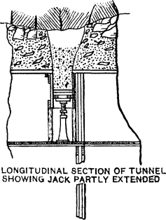
The method used in making the closures where two sections of the arch came together is shown by Fig. 17.
Skip to Text
Fig. 17.
SKETCH SHOWING METHOD OF MAKING ARCH CLOSURE
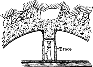
CROSS-SECTION OF TUNNEL SHOWING JACK PARTLY EXTENDED


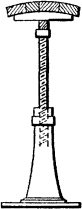
PLAN OF BOX PLAN OF PLUNGER BOTTOM OF BOX
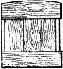
END VIEW END VIEW OF PLUNGER JACK FULLY EXTENDED
Water-proofing.—As already pointed out, the original design for the lining of these tunnels provided for a brick arch. It was intended to cover this arch with water-proofing, this latter extending over the whole of the roof and down the sides as far as the bottom of the conduit lines. The water-proofing was to be placed against the sand-walls 10 and 14. Over the arch, after being placed, it was to be protected by an armor course of brick, laid flat, the space between the brick and the excavation, which was required to be not less than 4 in. (and, as a matter of fact, was actually a great deal more), being filled with rock packing. Besides filling the space, this latter was designed to allow any water from the roof of the tunnel to find its way easily to the top of the sand-wall, from there being carried through the 4-in. cast-iron pipes, shown on Plate VIII4 to the side ditches in the floor of the tunnel.
All the water-proofing placed in these tunnels was of felt and pitch, six-ply felt and seven layers of pitch. The felt was required to be Hydrex, or of equal quality, and the pitch, “Straight run coal-tar pitch which will soften at 60° Fahr., of a grade in which the distillate oils will have a specific gravity of 1.05.”
In addition to tests as to the above qualities, the pitch was analyzed
It was considered quite important that there should be absolutely free drainage on the outer side of the lining, so that there would be no chance for any water to acquire a head. More than three-quarters of the length of these tunnels is below the level of mean high water, and while it was hardly expected that there would be any direct connection between the water in the Hudson River and the groundwater of the section penetrated, it was thought wise to provide ample drainage.
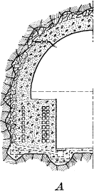
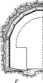
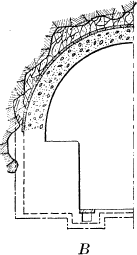
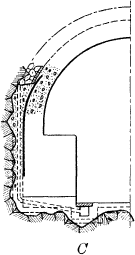
Before the lining was started, however, the excavation had progressed sufficiently to show that the tunnels, while very wet in places, and varying from that to quite damp, would be, on the whole, much dryer than had been anticipated. It was then decided to substitute concrete for the brick in the arch and omit the water-proofing over the top, except at places where water came into the tunnels in sufficiently large quantities to form practically a continuous stream. Three general types of construction for the arch were decided on, as shown in Fig. 18. The first, as shown at A, was to be used where the tunnel was quite dry. In this type, the sand-wall was omitted entirely, and the concrete and rock packing were built up together, the rock packing impinging to a certain extent on the concrete, and the concrete squeezing somewhat into the rock packing, as shown by Fig. 4, Plate XXV. The section shown at B was used where the tunnels were damp, or where there were slight droppers not forming a continuous stream. The back lagging, of 1-in. boards, which was left in place, provided a practically smooth outer surface on the concrete arch, and allowing the concrete and rock packing to be built almost simultaneously. It was considered that the free drainage through the rock packing, the surface of the boards, and the smooth outer surface of the concrete in the arch would allow the comparatively small quantity of water in these parts of the tunnel to find its way to the sides, and thence to the ditches at the bottom, rather than to percolate through the concrete, and this proved to be very generally the case, as is shown by the dry condition of the tunnel as built. The back lagging was used over the arch, both where the sand-wall was built and where it was omitted, as well as being placed over the water-proofing of the arch as an armor course where water-proofing was required. Where the sand-walls C, Fig. 18.
Skip to Text
Fig. 18.
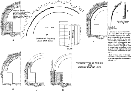
VARIOUS TYPES OF ARCHES, AND WATER-PROOFING USED
Method of making joint when work on section was not continuous. Part of joint on radial line, part sloping slightly toward outside of arch.
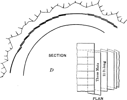
Method of Lapping Mats over Arch
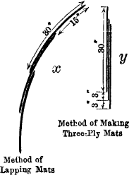
DETAILS OF WATER-PROOFING One layer of felt with 4" overlap to be nailed to lagging of inch boards, using tin washers on nails over the whole of the intrados of the arch before starting any concrete or placing any of the permanent felt and pitch water-proofing. The water-proofing over the arch can be laid in mats of three thicknesses of felt properly joined together with pitch made as shown diagrammatically at “x” Each of these mats of three-ply felt will be overlapped half the width of the mat, as shown diagrammatically at “y”
The third method provided for water-proofing the whole of the arch, and was the same as B except for the addition of the water-proofing inside the back lagging. In placing this water-proofing, the felt was cut in strips about 11 ft. long (about 1 ft. longer than the length of a section of arch), and six thicknesses were cemented together with hot pitch. These mats were then laid shingle-fashion, as shown at D, Fig. 18, up the sides of the arch until a space about 5 ft. wide remained at the crown; shorter mats were then brought out over this, laying them perpendicular to the axis of the tunnel. Care was taken in making all laps, irrespective of the direction in which the arch was built, so that they would lay with the grade, that is, so that the water would tend to flow over the edges of the laps rather than against them.
Most of the wet sections of the tunnel were at the ends, where sand-walls had been built for the purpose of providing a smooth surface against which the water-proofing was to be placed; there were several wet places at isolated points in the tunnels, however, and, in order to avoid building sand-walls at these points, the method shown at E, Fig. 18, was adopted. This involved a slightly larger excavation, 2 ft. outside of the neat line, up to the height of the top of the bench, where there was not already that much room. The bench-wall was built with a back form on the neat line, the water-proofing was placed as shown, protected by an armor course of brick, and then continued over the arch when this latter was built. The excavation and refilling with rock packing were done at the contractor’s expense, which he was willing to assume rather than build these short sections of sand-wall.
Skip to text
PLATE XXVII. TRANS. AM. SOC. CIV. ENGRS. VOL. LXVIII, No. 1154. LAVIS ON PENNSYLVANIA R.R. TUNNELS: BERGEN HILL TUNNELS.
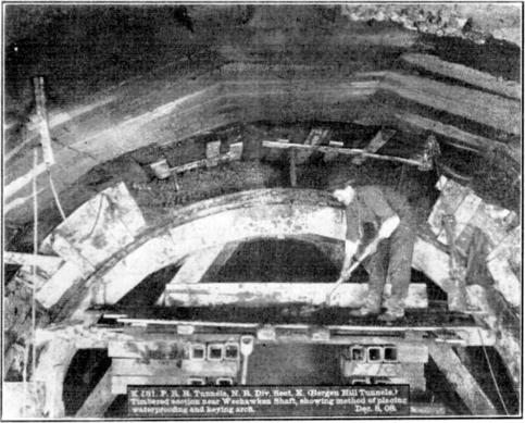
Fig. 1. K 181. P.R.R. Tunnels, N. R. Div. Sect. K. (Bergen Hill Tunnels.) Timbered section near Weehawken Shaft, showing method of placing waterproofing and keying arch. Dec. 8, 08.
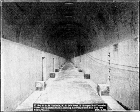
Fig. 2. K 184. P.R.R. Tunnels, N. R. Div. Sect. K. (Bergen Hill Tunnels). View of completed tunnel looking Eastward from Sta. 323+60. South Tunnel. Feb. 8, 09.
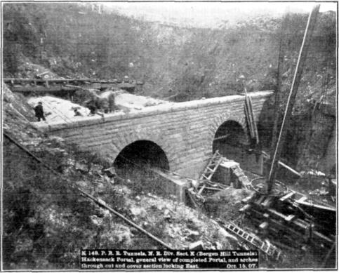
Fig. 3. K 149. P.R.R. Tunnels, N. R. Div. Sect. K. (Bergen Hill Tunnels) Hackensack Portal, general view of completed Portal, and arches through cut and cover section looking East. Oct. 15, 07.
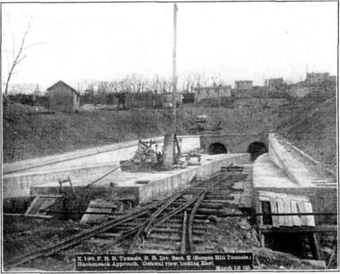
Fig. 4. K 190. P.R.R. Tunnels, N. R. Div. Sect. K. (Bergen Hill Tunnels.) Hackensack Approach. General view, looking East. March 16, 09.
The method of water-proofing that part of the timbered section which was very wet, is shown at F, Fig. 18, and in Fig. 4, Plate XXVI, and Fig. 1, Plate XXVII. A lagging of 1-in. boards was nailed up the sides and to the soffit of the segmental timbering, all the spaces outside of this lagging being carefully filled with rock packing. Before starting any concrete work, a single thickness of water-proofing felt was nailed to the inner side of the lagging, which not only served to protect the finished surfaces of the concrete from the
In placing the water-proofing in this section on the sides, the strips of felt were placed vertically, nailed at the top to the wall-plate, to support their weight, and lapped and cemented with pitch to the sides as on the sand-walls, except that there was no trouble from the overhang. After the bench-wall had been built, the felt was cut just below the nails and about 2 ft. above the top of the bench, so that the mats which were placed over the arch could be inserted behind it. The roof was covered with three-ply mats and lapped over a little more than half, as shown diagrammatically on the drawing.
When the upper part of the arch was reached, where the cementing strength of the pitch was not sufficient to hold the felt in place, the mats were braced temporarily from the centering, as shown by Fig. 1, Plate XXVII, until the concrete could be packed against it.
Where the water-proofing was placed against the sand-wall, the method of securing the sheets at the top is shown in the small sketch on Fig. 14 and by Figs. 3 and 4, Plate XXIV. Fig. 3, Plate XXV, shows the laps of the sheets and the method of hanging. At the start an attempt was made to stick the water-proofing to the sand-wall, but this could not be done on account of its dampness and the overhang at the top.
The sand-wall water-proofing was kept about 35 ft. ahead of the finished bench-wall, as shown by Fig. 3, Plate XXV. As the bench-wall form was moved ahead and set, the mat was braced back against the sand-wall from the forms at a point just above the top of the finished bench, care being taken to avoid wrinkles, as, if these were once formed, it was practically impossible to straighten them out.
The completion of the bench-wall left the upper part of this water-proofing stretched taut across the curved top of the sand-wall, forming a chord of the arc. As the arch was built up, the top was gradually slackened so as to allow the concrete to press the mat back into place until the top of the sand-wall was reached, when the end was turned in, as shown at C, Fig. 18, or the water-proofing was continued over the arch, if that was necessary.
The desire to obtain a dry tunnel, and the methods adopted to A, Fig. 18, could have been used exclusively, and, except for the fact that monolithic concrete might not have been obtained, there would have been no objection to building longer lengths.
The quantity of water reaching the tunnel drains and flowing out of their lower ends after the completion of the lining was about 100,000 gal. per day, or 75 gal. per min.; of this it is estimated that considerably less than 1% comes through the lining in the form of leaks. The very general distribution of this water over the roof is indicated by the fact that, during the excavation of the first 1,000 ft. of both tunnels from the Weehawken end, oilskins had to be provided for the laborers to induce them to work at all. The success, therefore, of the rock packing as a means of diverting this water to the side drains, is shown, especially in view of the fact that, excluding the cut-and-cover section, only 10% of the length of the arch, 1,189 ft., was water-proofed.
Considerable care was taken to make all joints in the concrete which were in such a position that water might follow through them to the inside of the tunnel lining, in such a manner that they would slope outward toward the rock. The top of the sand-wall is shown by Figs. 14 and 18. The slope of the back of the foundation may be noted in Fig. 18, and the method of making the joint in the arch, in the few instances where a section was not completed at one operation, is shown at A, Fig. 18. These joints in the arch were not allowed to be made above a point 60° above the springing line.
Skip to Text
Fig. 19.
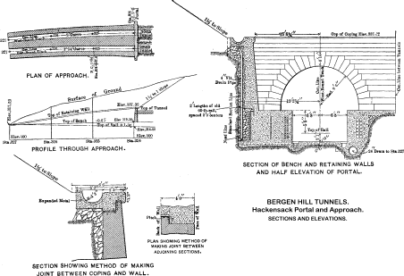
BERGEN HILLS TUNNELS. Hackensack Portal and Approach. SECTIONS AND ELEVATIONS.
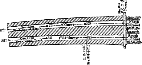
PLAN OF APPROACH.
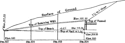
PROFILE THROUGH APPROACH.
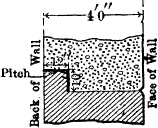
SECTION SHOWING METHOD OF MAKING JOINT BETWEEN COPING AND WALL.
PLAN SHOWING METHOD OF MAKING JOINT BETWEEN ADJOINING SECTIONS.
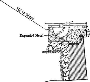
SECTION OF BENCH AND RETAINING WALLS AND HALF ELEVATION OF PORTAL.
Hackensack Portal and Approach.
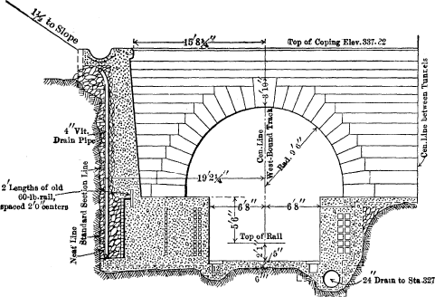
The approach cut at the western end is 300 ft. long, the alignment being a 2° curve, as shown in Fig. 19. The bench-walls and conduit lines built throughout the length of the tunnels are extended through the approach cut, the top of the former gradually sloping from the portal to the mouth of the cut, where they are just level with the top of the rail, the conduits also being depressed to the same relative position with the tops of the benches.
The top of the rock at the mouth of the cut, Station 327, was from 4 to 6 ft. below the top of the rail, and gradually rose through Fig. 19. The rock throughout the approach was water-bearing to a considerable extent, and a face-wall was built at the sides with free drainage, through rock packing and vitrified and cast-iron drains behind it, to keep this water from flowing over the tops of the bench-walls, and also to keep the lines of conduits dry.
The retaining walls were built in 25-ft. sections, the joints corresponding to those in the benches, being at the even stations, +08, +33, +58, and +83. V-shaped joints were made down the face, and the ends of the sections were made as shown by Fig. 19. The back part of the joint was mopped with hot pitch before the next section was built, so that there was practically no bond between any two adjoining sections.
The concrete in these walls was placed late in the season, and the expansion cracks, which were entirely confined to the V-shaped joints, were quite small even in the coldest weather of the following winter, nor were there any indications during the past summer of any stresses due to expansion. The coping and drain at the top of the wall were built together, but separate from the rest of the wall, the joint being made as shown in the sketch on Fig. 19. Thus far, there has seemed to be no seepage through either the vertical or horizontal joints.
The portal is built of granite, a half elevation being shown on Fig. 19, the stone being supplied by the Millstone Granite Company, Millstone Point, Conn. Fig. 3, Plate XXVII, shows the portal and the cut-and-cover section after the arches were completed but not covered.
The forms for the concrete in the approach were made of ordinary dressed lumber, and the surface was rubbed twice after the forms were removed, which was as soon as possible after the concrete had set. The surface was first very lightly rubbed with a piece of soft, light-colored, sandstone to remove any irregularities, being wetted slightly if necessary while being rubbed. After the concrete had become fairly hard and dry, it was rubbed a second time and a uniform texture and color obtained. The completion of this work was delayed until the second week in January, and considerable difficulty was encountered in obtaining a good finish of that part which was built after Plate XXVII.
TABLE 6.
Title. Day. Night.
No. Rate. Amount. No. Rate. Amount.
Walking bosses 2 $5.00 $10.00
Timekeeper 2 3.00 6.00
Watchmen 5 $2.00 $10.00
Waterboys 1 1.50 1.50
Carpenter foremen 2 3.50 7.00 1 4.00 4.00
Carpenters 14 2.50 35.00 8 2.50 20.00
Pipe-fitters 1 3.00 3.00
Pipe-fitter’s helper 1 1.75 1.75
Wheelwright 1 2.75 2.75
Wheelwright’s helper 1 1.75 1.75
Blacksmith 1 3.00 3.00
Blacksmith’s helper 1 1.75 1.75
Foremen riggers 1 3.00 3.00
Riggers 6 1.75 10.50
Foremen trackmen 1 3.00 3.00
Trackmen 6 1.50 9.00
Machinist 2 3.00 6.00
Machinist’s helper 1 1.75 1.75
Electrician 2 3.00 6.00 1 2.50 2.50
Electrician’s helper 1 1.75 1.75
Lampman 1 1.50 1.50
Pumpman 1 1.50 1.50
Finishers 3 2.50 7.50
Hoist engineers 12 3.00 36.00
Dinky engineers 5 2.75 13.75 1 2.75 2.75
Brakemen 5 1.75 8.75 1 1.75 1.75
Switchmen 1 1.50 1.50
Barnmen 1 2.00 2.00 1 2.50 2.50
Drivers 9 1.50 13.50
Foremen ductmen 2 2.50 2.50
Ductmen 5 2.00 10.00
Foremen laborers 13 3.50 45.50 2 3.50 7.00
Laborers 120 1.75 210.00 20 1.75 35.00
Compressor engineer 1 3.50 3.50 1 3.50 3.50
Firemen 2 2.50 5.00 1 2.50 2.50
Oiler 1 1.75 1.75
Coal passers 2 1.75 3.50 1 1.75 1.75
Totals 334 $469.75 50 $108.25
Total daily labor expense $578.00
The water finding its way into the side ditches in the approach, which of course included all rain falling in this area, was intercepted just inside the portal and carried back to the mouth of the cut through 24-in. cast-iron pipes laid beneath the conduits in the central bench-wall, thus disposing by natural drainage of a not inconsiderable
About 100 ft. of the tunnel immediately east of the Hackensack Portal was built by the cut-and-cover method, and the arch section used in the tunnel was modified by widening the haunches, the thickness of the arch at the crown being gradually increased from 22 in. at the portal, Station 324, to 34 in. at Station 323, where the regular segmental timbering at the tunnel commenced. A general view of the approach during construction is shown by Fig. 1, Plate XXV.
Contractor’s Organization.
Table 6 shows approximately the number of men employed daily on the tunnel lining, by both the contractor and the sub-contractors, their occupation, the average rate of wages and the total daily expense for labor when the work was in full swing.
Engineering Organization.
The whole of the work of the North River Division was designed and executed under the direction of Charles M. Jacobs, M. Am. Soc. C. E., Chief Engineer, and James Forgie, M. Am. Soc. C. E., Chief Assistant Engineer, the construction of Section “K,” Bergen Hill Tunnels, being directly in charge of the writer as Resident Engineer.
PENNSYLVANIA TUNNEL AND TERMINAL RAILROAD COMPANY, SECTION “K”—BERGEN HILL TUNNELS.
Organization of Staff of Resident Engineer.
Organization Previous to the Holing Through of the Tunnels.
Fig. 20.
Resident Engineer.
Assistant Engineer. Assistant Engineer.
Cost and Office Records. Field Inspection. Alignment.
Weehawken. Hackensack. Weehawken. Hackensack.
Inspector. Chief Inspector. Chief Inspector.
Two Clerks. Stenographer. Telephone Operator. Messenger. Janitors. Inspector, N. Tunnel. ——”—— S. Tunnel. ——”—— Mixer. ——”—— Excavation and Force Account. Inspector, Night. Cement Warehouseman. Inspector, N. Tunnel. ——”—— S. Tunnel. ——”—— Mixer. ——”—— Excavation and Force Account. Inspector, Night. Cement Warehouseman. Chief of Party. Instrumentman. Rodman. Chainman. Chief of Party. Instrumentman. Rodman. Chainman.
Conduit Inspector.
Organization After the Tunnels Had Been Holed Through.
Fig. 21.
Resident Engineer.
Assistant Engineer. Assistant Engineer.
Alignment.
Cost and Office Records. Field Inspection.
Tunnels. Conduit Inspector. 1 Instrumentman. 1 Draftsman. 2 Rodmen. 3 Chainmen.
Two Inspectors. Two Clerks. Stenographer. Telephone Operator. Messenger. Janitor. Chief Inspector. | 8 Tunnel Inspectors. 2 Mixer Inspectors. 1 Night Inspector. Inspector, Hackensack Approach.
The general organization of the staff is shown by the two diagrams, Figs. 20 and 21. Fig. 20 shows the organization previous to the holing through of the tunnels, during which time a separate office was maintained at the western end for the use of the men stationed there; Fig. 21 shows the organization during the latter part of the time, after the tunnels were holed through. The Assistant Engineer in charge of the construction was J. R. Taft, Assoc. M. Am. Soc. C. E.; the Chief Inspector, J. S. Frazer, Jun. Am. Soc. C. E., had charge of about 75% of the work of the lining of the tunnels. The alignment has been from the beginning under the charge of R. L. Reynolds, Assistant Engineer.
List of Illustrations
(added by transcriber)
Plates are numbered continuously through the volume; Figures are numbered from 1 within each article.
Some illustrations have been repositioned to avoid breaking up the text. Page numbers in the table refer to the original printed volume. Plates were unpaginated; numbers such as “85” or “129” mean “facing page 84“, “facing page 128”. When a Figure took up a full (numbered) page, its page number is shown in italics. They may be slightly out of sequence with nearby page numbers.
Plate Page
XXI. Hackensack Portal, Bergen Hill Tunnels; Method of Using Cross-Section Rod; and Belt Conveyor for Handling and Placing Concrete 85
XXII. Scaffold Car; Headhouse; and Round Holes in Concrete Forms 87
XXIII. Record of Drilling, Air Pressure, Mucking, etc., in Bergen Hill Tunnels 95
XXIV. Belt Conveyor for Handling and Placing Concrete; Water-Proofing, Portion of Completed Sand-Wall, etc.; and Methods of Placing Concrete in Forms and Bench-Walls 119
XXV. Telephone and Telegraph Ducts and Mandrels; Tunnel Lining Forms; Placing Water-Proofing; and Section of Completed Lining 129
XXVI. Form of Circuit-Breaker Chamber and Traveling Gantry; Forms for Storage Chamber; Rock Packing Over Arches; Method of Water-Proofing in Timbered Tunnels, etc. 137
XXVII. Method of Placing Water-Proofing and Keying Arch; View of Completed Tunnel; General View of Completed Hackensack Tunnel and Arches Through Cut-and-Cover Section; and View of Hackensack Approach 145
Fig. 1. Drilling Method No. 1 88
2. Drilling Method No. 2 89
3. Drilling Method No. 3 90
4. Drilling Method No. 4 91
5. Muck Car Used at Weehawken Shaft 92
6. Progress Profiles of North and South Tunnels Showing Monthly Excavation 93
7. Method of Emptying Dump Cars at Weehawken Shaft 98
8. Ventilation System (no caption) 101
9. Progress Profile—North Tunnel 107
10. Sketch Showing Division of Lining for Purposes of Construction, and Names of Sections 115
11. A Cross-Section of Hains Mixer Installation, at Weehawken Shaft B Cross-Section of Hains Mixer Installation, Stone and Sand Bins Above and Screen of Crusher, at Hackensack Portal 118
12. Details of Traveling Gantry Used in the Construction of the Tunnel Lining 121
13. Plan Showing Various Methods of Building Floor and Foundation, and Details of Forms 125
14. Traveling Form for Building Sand-Wall 128
15. Electrical Conduits: Methods of Laying, Rodding, etc. 131
16. Details of Traveling Forms Used in the Construction of the Bench Walls 131
17. Sketch Showing Method of Making Arch Closure 141
18. Various Types of Arches, and Water-Proofing Used 143
19. Bergen Hills Tunnels. Hackensack Portal and Approach. Sections and Elevations. 148
20. Organization of Staff of Resident Engineer. Organization Previous to the Holing Through of the Tunnels. 150
21. Organization of Staff of Resident Engineer. Organization After the Tunnels Had Been Holed Through. 151