Chapter XI · MAGNETIC EFFECTS OF THE ELECTRIC CURRENT.
Reading edition
91. Electromagnetism is the name given to magnetism that is developed by electricity. We have seen that if a magnetic needle be placed in the field of a magnet, its N pole will point in the direction taken by the lines of force as they pass from the N to the S pole of the magnet.
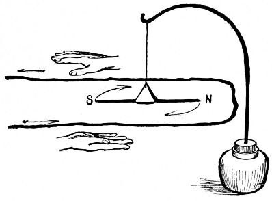
Fig. 89.
92. Lines of Force about a Wire. When a current passes through a wire, the magnetic needle placed over or under it tends to take a position at right angles to the wire. Fig. 89 shows such a wire and needle, and how the needle is deflected; it twists right around from its N and S position as soon as the current begins to flow. This shows that the lines of force pass around the wire and not in the direction of its length. The needle does not swing entirely perpendicular to the wire, that is, to the E and W line, because the earth is at the same time pulling its N pole toward the N.
Fig. 90 shows a bent wire through which a current passes from C to Z. If you look along the wire from C toward the points A and B, you will see that under the wire the lines of force pass to the left. Looking along the wire from Z toward D you will see that the lines of force pass opposite to the above, as the current comes toward you. This is learned by experiment. (See "Study," Exp. 152, § 385, etc.)
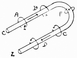
Fig. 90.
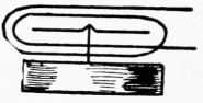
Fig. 91.
Rule. Hold the right hand with the thumb extended (Fig. 89) and with the fingers pointing in the direction of the current, the palm being toward the needle and on the opposite side of the wire from the needle. The north-seeking pole will then be deflected in the direction in which the thumb points.
93. Current Detectors. As there is a magnetic field about a wire when a current passes through it, and as the magnetic needle is affected, we have a means of detecting the presence of a current. When the current is strong it is simply necessary to let it pass once over or under a needle; when it is weak, the wire must pass several times above and below the needle, Fig. 91, to give the needle motion. (See "Apparatus Book," Chapter XIII., for home-made detectors.)
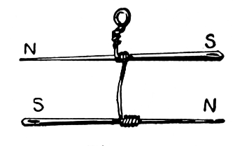
Fig. 92.
94. Astatic Needles and Detectors. By arranging two magnetized needles with their poles opposite each other, Fig. 92, an astatic needle is formed. The pointing-power is almost nothing, although their magnetic fields are retained. This combination is used to detect feeble currents. In the ordinary detector, the tendency of the needle to point to the N and S has to be overcome by the magnetic field about the coil before the needle can be moved; but in the astatic detector and galvanoscope this pointing-power is done away with. Fig. 93 shows a simple astatic galvanoscope. Fig. 67 shows an astatic galvanometer for measuring weak currents.
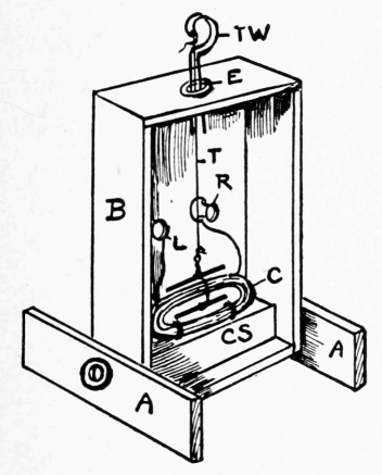
Fig. 93.
95. Polarity of Coils. When a current of electricity passes through a coil of wire, the coil acts very much like a magnet, although no iron enters into its construction. The coil becomes magnetized by the electric current, lines of force pass from it into the air, etc. Fig. 94 shows a coil connected to copper and zinc plates, so arranged with cork that the whole can float in a dish of dilute sulphuric acid. The current passes as shown by the arrows, and when the N pole of a magnet is brought near the right-hand end, there is a repulsion, showing that that end of the coil has a N pole.
Rule. When you face the right-hand end of the coil, the current is seen to pass around it in an anti-clockwise direction; this produces a N pole. When the current passes in a clockwise direction a S pole is produced.
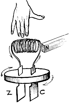
Fig. 94.
96. Electromagnets. A coil of wire has a stronger field than a straight wire carrying the same current, because each turn adds its field to the fields of the other turns. By having the central part of the coil made of iron, or by having the coil of insulated wire wound upon an iron core, the strength of the magnetic field of the coil is greatly increased.
Lines of force do not pass as readily through air as through iron; in fact, lines of force will go out of their way to go through iron. With a coil of wire the lines of force pass from its N pole through the air on all sides of the coil to its S pole; they then pass through the inside of the coil and through the air back to the N pole. When the resistance to their passage through the coil is decreased by the core, the magnetic field is greatly strengthened, and we have an electromagnet.
The coil of wire temporarily magnetizes the iron core; it can permanently magnetize a piece of steel used as a core. (See "Study," Chapter XXII., for experiments.)
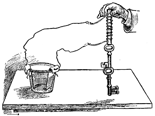
Fig. 95.
97. Forms of Electromagnets. Fig. 95 shows a straight, or bar electromagnet. Fig. 96 shows a simple form of horseshoe electromagnet. As this form is not easily wound, the coils are generally wound on two separate cores which are then joined by a yoke. The yoke merely takes the place of the curved part shown in Fig. 96. In Fig. 97 is shown the ordinary form of horseshoe electromagnet used for all sorts of electrical instruments. (See "Apparatus Book," Chapter IX., for home-made electromagnets.)
98. Yokes and Armatures. In the horseshoe magnet there are two poles to attract and two to induce. The lines of force pass through the yoke on their way from one core to the other, instead of going through the air. This reduces the resistance to them. If we had no yoke we should simply have two straight electromagnets, and the resistance to the lines of force would be so great that the total strength would be much reduced. Yokes are made of soft iron, as well as the cores and armature. The armature, as with permanent horseshoe magnets, is strongly drawn toward the poles. As soon as the current ceases to flow, the attraction also ceases.
Fig. 96 Fig. 97.
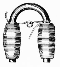
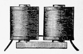
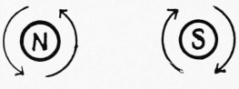
Fig. 98.
Beautiful magnetic figures can be made with horseshoe magnets. Fig. 98 shows that the coils must be joined so that the current can pass around the cores in opposite directions to make unlike poles. (See "Study," Exp. 164 to 173.)