Thomson Houston Dynamo Operates.
Reading edition
In the diagram Fig. 19 the rotation is as in practice against the hands of the watch when seen from the commutator end of shaft. The three coils of the armature are represented by three lines A, B, C, united at their inner extremities each being joined to a segment of the commutator. There are two positive brushes P and F and two negative ones P´ and F´. The current delivered to P and F goes round one of the field magnet coils, then to the outer circuit consisting of regulating gear, lamps, motors, etc., through the other field magnet coil to brushes P´ and F´. Now from Fig. 20, we observe that supposing the loop to be rotating against the hands of the watch in a magnetic field the diagram represents by arrows the direction of the electro-motive forces induced in those loops. The action is a maximum along the line of the resultant magnetic field m m´ and the minimum along the line n n´ which is at right angles to m m´. The reason that m m´ is not horizontal is that the induced poles of the armature is in advance of the poles of the field magnet and is constantly tending to be drawn back. Applying Fig. 20 to Fig. 19, we see that there will be an outward current in B, an inward one in C, A generating no current for that moment.
Now the following pair of brushes F F´ are shifted backward three times as far as P P´ is shifted forwards. When the current is the greatest possible the brushes P and F and P´ and F´ are 60° apart thus leaving P and F´ and P´ and F´ just 120° apart and since the segments of the commutator are each 120° in length[3] there will always be two coils in parralel with one another and in series with the third. Taking one sixth of a revolution and continuing all the way round we find the following tabulated statement showing brushes in contact with coils, to be true viz:—
{ P - C } { P´ }
From external circuit { } B { } to external circuit
{ F - A } { F´ }
{ P } { P´ - B }
” “ ” { } A { } ” “ ”
{ F } { F´ - C }
{ P - A } { P´ }
” “ ” { } C { } ” “ ”
{ F - B } { F´ }
{ P } { P´ - C }
” “ ” { } B { } ” “ ”
{ F } { F´ - A }
{ P - B } { P´ }
” “ ” { } A { } ” “ ”
{ F - C } { F }
{ P } { P´ - A }
” “ ” { } C { } ” “ ”
{ F } { F´ - B }
Now suppose the current to become to strong owing to any cause, the following brushes are made to recede. This can but shorten the time that the brushes are in contact with the commutator when the coil is passing through that position in which it is generating the maximum amount of current and also hasten the time when it goes into parralel with a comparatively idle coil. If the current is to weak then the brushes are made to close up thus reducing the time that the most active coil is in parralel with one less active and also makes the brushes be longer in contact with the segment when the coil is generating its maximum amount of current. The motion of advance and retreat of the brushes is accomplished by the Thomson Regulating Gear before described. On Fig. 23 can be seen all the dynamo’s details except the Controller magnet.
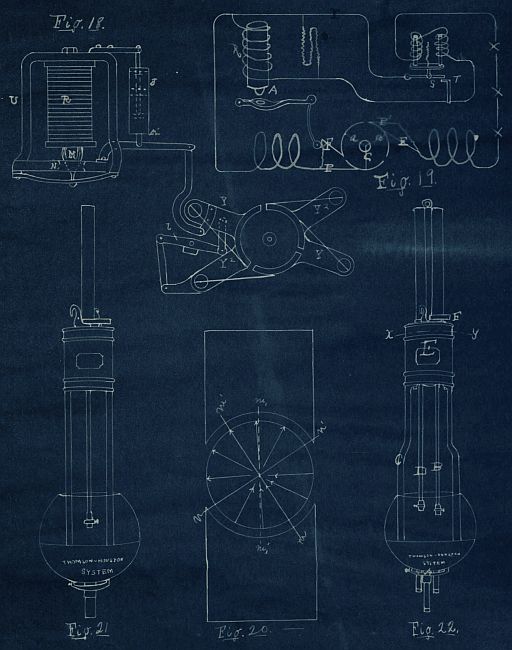
Fig. 18. Fig. 19. Fig. 20. Fig. 21. Fig. 22.
As regards the Thomson-Houston Dynamo it will be found to produce the steadiest and most uniform current of any dynamo now in use. It regulating gear is the simplest and most natural one ever used. In its ability to reduce the current simaltaneously to one tenth of its former quantity inside of one or two minutes without injury to itself and lamps it stands alone, in practice.
Fig. 23.
Your engraving representing “Dynamo Electric Machine with Thomsons Spherical Armature”
—Taken from one of your catalogues, and pasted on a sheet of this paper—
In a system the most important thing next to the dynamo is the lamps. The first experimenter who produced an electric glow was Otto von Guericke. But neither the glow nor electric spark have been used to produce electric light for practical purposes, this was left to the voltaic arc on the one hand and the incandescent lamp on the other. Davy in 1800 mentions experiments in which electric light was obtained by electric sparks between two carbon points. He showed the arc[4] light for the first time in 1810 at the Royal Institute, which with Foucalt’s hand regulator (1844) Deleuil lit the Place de la Concorde, Paris. Thomas Wright in London (1845) devised the first apparatus which automatically adjusted the carbons. W. C. Staite used the electric current for the regulation of the carbons in 1848. In 1855 Serrin constructed a lamp which would have been used on a large scale had it not been for the cost of generating electricity. In 1876 Paul Jablochkoff invented his electric candles and in 1881 there were 4000 in use, but as their use increased their defects were found out. Regulated lamps were again brought into use and with them experimenters again endeavored to solve the problem of dividing the electric light. In 1877 Tschikoliff solved the problem in a very simple manner. He reasoned that, if the current be divided and part go through the carbons and make the arc and the rest go through an electromagnet and regulate the arc and the the current unite and when another light is wanted the current be again divided and reunited, the current may be divided any number of times and the scheme work nicely. When put in practice it worked very nicely and is used on most lamps at present. Suppose there be a lamp placed in the circuit. The current divides and the larger half goes through the carbons, as here there is no resistance as the carbons touche, while the remainder, going through a spiral of high resistance, is small. When the carbons burn away a little the arc is formed and the resistance increasing brings the regulating gear into operation. Now the strength of the current is the same after it has gone through the lamp as before because the current is going to get through either one way or the other, hence any number of lamps may go on in series, depending only upon the tension of the current.
Incandescent lamps were produced as early as 1859 but not till 1879 when Swan, Edison, Sawyer and others were they ever in a practical form. The first glow lamp Edison constructed had platinum wire to be heated. He however examined the properties of organic substances and finally fixed on bamboo fibre. The bamboo is divided into fibres one millimeter in diameter and twelve millimeters long. These fibres are pressed in U-shaped moulds and baked in ovens where they are allowed to become carbonized. The carbonized filament is attached to platinum wires which are fused in a glass vessel from which the air has been exhausted. We will speak more fully of the incandescent lamp when describing the Thomson Houston System’s incandescent lamp.
The Thomson Arc lamps was used by the Thomson Houston System since its begining till about two years ago when they stopped manufacturing them, only furnishing broken parts. The arc lamps at present used is