Chapter X · LOCOMOTIVE ENGINES ON RAILWAYS.
Reading edition
High-pressure Engines. — Leupold's Engine. — Trevithick and Vivian. — Effects of Improvement in Locomotion. — Historical Account of the Locomotive Engine. — Blenkinsop's Patent. — Chapman's Improvement. — Walking Engine. — Stephenson's First Engines. — His Improvements. — Liverpool and Manchester Railway Company. — Their Preliminary Proceedings. — The Great Competition of 1829. — The Rocket. — The Sanspareil. — The Novelty. — Qualities of the Rocket. — Successive Improvements. — Experiments. — Defects of the Present Engines. — Inclined Planes. — Methods of surmounting them. — Circumstances of the Manchester Railway Company. — Probable Improvements in Locomotives. — Their capabilities with respect to speed. — Probable Effects of the Projected Railroads. — Steam Power compared with Horse Power. — Railroads compared with Canals.
(80.) In the various modifications of the steam engine which we have hitherto considered, the pressure introduced on one side of the piston derives its efficacy either wholly or partially from the vacuum produced by condensation on the other side. This always requires a condensing apparatus, and a constant and abundant supply of cold water. An engine of this kind must therefore necessarily have considerable dimensions and weight, and is inapplicable to uses in which a small and light machine only is admissible. If the condensing apparatus be dispensed with, the piston will always be resisted by a force equal to the atmospheric pressure, and the only part of the steam pressure which will be available as a moving power, is that part by which it exceeds the pressure of the atmosphere. Hence, in engines which do not work by condensation, steam of a much higher pressure than that of the atmosphere is indispensably necessary, and such engines are therefore called high-pressure engines.
We are not, however, to understand that every engine, in which steam is used of a pressure exceeding that of the atmosphere, is what is meant by a high-pressure engine; for in the ordinary engines in common use, constructed on Watt's principle, the safety-valve is loaded with from 3 to 5 lbs. on the square inch; and in Woolf's engines, the steam is produced under a pressure of 40 lbs. on the square inch. These would therefore be more properly called condensing engines than high-pressure engines; a term quite inapplicable to those of Woolf. In fact, by high-pressure engines is meant engines in which no vacuum is produced, and, therefore, in which the piston works against a pressure equal to that of the atmosphere.
In these engines, the whole of the condensing apparatus, viz. the cold-water cistern, condenser, air-pump, cold-water pump, &c. are dispensed with, and nothing is retained except the boiler, cylinder, piston, and valves. Consequently, such an engine is small, light, and cheap. It is portable also, and may be moved, if necessary, along with its load, and is therefore well adapted to locomotive purposes.
(81.) High-pressure engines were one of the earliest modifications of the steam engine. The contrivance, which is obscurely described in the article already quoted (27.), from the Century of Inventions, is a high-pressure engine; for the power there alluded to is the elastic force of steam working against the atmospheric pressure. Newcomen, in 1705, applied the working-beam, cylinder, and piston to the atmospheric engine; and Leupold, about 1720, combined the working-beam and cylinder with the high-pressure principle, and produced the earliest high-pressure engine worked by a cylinder and piston. The following is a description of Leupold's engine:—
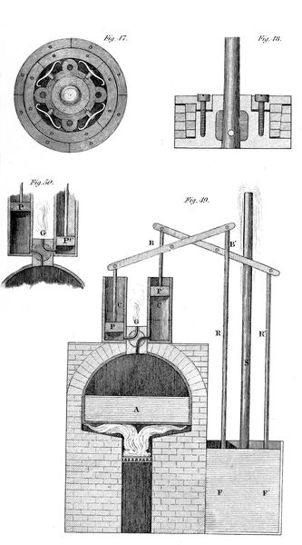
A (fig. 49.) is the boiler, with the furnace beneath it; C C´ are two cylinders with two solid pistons, P P´, connected with the working-beams B B´, to which are attached the pump-rods, R R´, of two forcing-pumps, F F´, which communicate with a great force-pipe S; G is a four-way cock (66.) already described. In the position in which it stands in the figure, the steam is issuing from below the piston P into the atmosphere, and the piston is descending by its own weight; steam from the boiler is at the same time pressing up the piston P´, with a force equal to the difference between the pressure of the steam and that of the atmosphere. Thus the piston R of the forcing-pump is being drawn up, and the piston P´ is forcing the piston R´ down, and thereby driving water into the force-pipe S. On the arrival of the piston P at the bottom of the cylinder C, and P´ at the top of the cylinder C´, the position of the cock is changed as represented in fig. 50. The steam, which has just pressed up the piston P´, is allowed to escape into the atmosphere, while the steam, passing from the boiler below the piston P, presses it up, and thus P ascends by the steam pressure, and P´ descends by its own weight. By these means the piston R is forced down, driving before it the water in the pump cylinder into the force-pipe S, and the piston R´ is drawn up to allow the other pump-cylinder to be re-filled; and so the process is continued.
A valve is placed in the bottom of the force-pipes, to prevent the water which has been driven into it from returning. This valve opens upwards; and, consequently, the weight of the water pressing upon it only keeps it more effectually closed. On each descent of the piston, the pressure transmitted to the valve acting upwards being greater than the weight of the water resting upon it, forces it open, and an increased quantity of water is introduced.
(82.) From the date of the improvement of Watt until the commencement of the present century, high-pressure engines were altogether neglected in these countries. In the year 1802, Messrs. Trevithick and Vivian constructed the first high-pressure engine which was ever brought into extensive practical use in this kingdom. A section of this machine, made by a vertical plane, is represented in fig. 51.
The boiler A B is a cylinder with flat circular ends. The fire-place is constructed in the following manner:—A tube enters the cylindrical boiler at one end; and, proceeding onwards, near the other extremity, is turned and recurved, so as to be carried back parallel to the direction in which it entered. It is thus conducted out of the boiler, at another part of the same end at which it entered. One of the ends of this tube communicates with the chimney E, which is carried upwards, as represented in the figure. The other mouth is furnished with a door; and in it is placed the grate, which is formed of horizontal bars, dividing the tube into two parts; the upper part forming the fire-place, and the lower the ash-pit. The fuel is maintained in a state of combustion, on the bars, in that part of the tube represented at C D; and the flame is carried by the draft of the chimney round the curved flue, and issues at E into the chimney. The flame is thus conducted through the water, so as to expose the latter to as much heat as possible.
A section of the cylinder is represented at F, immersed in the boiler, except a few inches of the upper end, where the four-way cock G is placed for regulating the admission of the steam. A tube is represented at H, which leads from this four-way cock into the chimney; so that the waste steam, after working the piston, is carried off through this tube, and passes into the chimney. The upper end of the piston-rod is furnished with a cross-bar, which is placed in a direction at right angles to the length of the boiler, and also to the piston-rod. This bar is guided in its motion by sliding on two iron perpendicular rods fixed to the sides of the boiler, and parallel to each other. To the ends of this cross-bar are joined two connecting rods, the lower ends of which work two cranks fixed on an axis extending across and beneath the boiler, and immediately under the centre of the cylinder. This axis is sustained in bearings formed in the legs which support the boiler, and upon its extremity is fixed the fly-wheel as represented at B. A large-toothed wheel is placed on this axis; which, being turned with the cranked axle, communicates motion to other wheels; and, through them, to any machinery which the engine may be applied to move.
As the four-way cock is represented in the figure, the steam passes from the boiler through the curved passage G above the piston, while the steam below the piston is carried off through a tube which does not appear in the figure, by which it is conducted to the tube H, and thence to the chimney. The steam, therefore, which passes above the piston presses it downwards; while the pressure upwards does not exceed that of the atmosphere. The piston will therefore descend with a force depending on the excess of the pressure of the steam produced in the boiler above the atmospheric pressure. When the piston has arrived at the bottom of the cylinder, the cock is made to assume the position represented in the figure 52. This effect is produced by the motion of the piston-rod. The steam now passes from above the piston, through the tube H, into the chimney, while the steam from the boiler is conducted through another tube below the piston. The pressure above the piston, in this case, does not exceed that of the atmosphere; while the pressure below it will be that of the steam in the boiler. The piston will therefore ascend with the difference of these pressures. On the arrival of the piston at the top of the cylinder, the four-way cock is again turned to the position represented in fig. 51., and the piston again descends; and in the same manner the process is continued. A safety-valve is placed on the boiler at V, loaded with a weight W, proportionate to the strength of the steam with which it is proposed to work.
Pl. XI.
Engr. by P. Maverick
In the engines now described, this valve was frequently loaded at the rate of from 60 to 80 lbs. on the square inch. As the boilers of high-pressure engines were considered more liable to accidents from bursting than those in which steam of a lower pressure was used, greater precautions were taken against such effects. A second safety-valve was provided, which was not left in the power of the engine-man. By this means he had a power to diminish the pressure of the steam, but could not increase it beyond the limit determined by the valve which was removed from his interference. The greatest cause of danger, however, arose from the water in the boiler being consumed by evaporation faster than it was supplied; and therefore falling below the level of the tube containing the furnace. To guard against accidents arising from this circumstance, a hole was bored in the boiler, at a certain depth, below which the water should not be allowed to fall; and in this hole a plug of metal was soldered with lead, or with some other metal, which would fuse at that temperature which would expose the boiler to danger. Thus, in the event of the water being exhausted, so that its level would fall below the plug, the heat of the furnace would immediately melt the solder, and the plug would fall out, affording a vent for the steam, without allowing the boiler to burst. The mercurial steam-gauge, already described, was also used as an additional security. When the force of the steam exceeded the length of the column of mercury which the tube would contain, the mercury would be blown out, and the tube would give vent to the steam. The water by which the boiler was replenished was forced into it by a pump worked by the engine. In order to economise the heat, this water was contained in a tube T, which surrounded the pipe H. As the waste steam, after working the piston, passed off through H, it imparted a portion of its heat to the water contained in the tube T, which was thus warmed to a certain temperature before it was forced into the boiler by the pump. Thus a part of the heat, which was originally carried from the boiler in the form of steam, was returned again to the boiler with the water with which it was fed.
It is evident that engines constructed in this manner may be applied to all the purposes to which the condensing engines are applicable.
(e) To the plates of the English edition has been added one, (plate A) representing a high-pressure engine as constructed by the West Point Foundry in the state of New York. The principal parts will be readily distinguished from their resemblance to the analogous parts of a condensing engine. The condenser and air-pump of that engine, it will be observed, are suppressed. At v x and y z are forcing-pumps by which a supply of water is injected into the boiler at each motion of the engine. For the four-way cock, used in the English high-pressure engines, a slide valve at r s, is substituted, and is found to work to much greater advantage. It is set in motion by an eccentric, in a manner that will be more obvious from an inspection of the plate than from any description.—A. E.
(f) A very safe and convenient boiler for a high-pressure engine has been invented in the United States by Mr. Babcock. The boiler consists of small tubes, into which water is flashed by a small forcing-pump at every stroke of the engine. The tubes are kept so hot in a furnace, as to generate steam of the required temperature, but not hot enough to cause any risk of the decomposition of the water. The strength of the apparatus is such, and the quantity of water exposed to heat at one time so small, as to leave hardly any risk of danger.—A. E.
(83.) Two years after the date of the patent of this engine, its inventor constructed a machine of the same kind for the purpose of moving carriages on railroads; and applied it successfully, in the year 1804, on the railroad at Merthyr Tydvil, in South Wales. It was in principle the same as that already described. The cylinder however was in a horizontal position, the piston-rod working in the direction of the line of road: the extremity of the piston-rod, by means of a connecting rod, worked cranks placed on the axletree, on which were fixed two cogged wheels: these worked in others, by which their motion was communicated finally to cogged wheels fixed on the axle of the hind wheels of the carriage, by which this axle was kept in a state of revolution. The hind wheels being fixed on the axletree, and turning with it, were caused likewise to revolve; and so long as the weight of the carriage did not exceed that which the friction of the road was capable of propelling, the carriage would thus be moved forwards. On this axle was placed a fly-wheel to continue the rotatory motion at the termination of each stroke. The fore wheels are described as being capable of turning like the fore wheels of a carriage, so as to guide the vehicle. The projectors appear to have contemplated, in the first instance, the use of this carriage on turnpike roads; but that notion seems to have been abandoned, and its use was only adopted on the railroad before mentioned. On the occasion of its first trial, it drew after it as many carriages as contained 10 tons of iron a distance of nine miles; which stage it performed without any fresh supply of water, and travelled at the rate of five miles an hour.
(84.) Capital and skill have of late years been directed with extraordinary energy to the improvement of inland transport; and this important instrument of national wealth and civilisation has received a proportionate impulse. Effects are now witnessed, which, had they been narrated a few years since, could only have been admitted into the pages of fiction or volumes of romance. Who could have credited the possibility of a ponderous engine of iron, loaded with several hundred passengers, in a train of carriages of corresponding magnitude, and a large quantity of water and coal, taking flight from Manchester and arriving at Liverpool, a distance of about thirty miles, in little more than an hour? And yet this is a matter of daily and almost hourly occurrence. Neither is the road, on which this wondrous performance is effected, the most favourable which could be constructed for such machines. It is subject to undulations and acclivities, which reduce the rate of speed much more than similar inequalities affect the velocity on common roads. The rapidity of transport thus attained is not less wonderful than the weights transported. Its capabilities in this respect far transcend the exigencies even of the two greatest commercial marts in Great Britain. Loads, varying from 50 to 150 tons are transported at the average rate of 15 miles an hour; but the engines in this case are loaded below their power; and in one instance we have seen a load—we should rather say a cargo—of wagons, conveying merchandise to the amount of 230 tons gross, transported from Liverpool to Manchester at the average rate of 12 miles an hour.
The astonishment with which such performances must be viewed, might be qualified, if the art of transport by steam on railways had been matured, and had attained that full state of perfection which such an art is always capable of receiving from long experience, aided by great scientific knowledge, and the unbounded application of capital. But such is not the present case. The art of constructing locomotive engines, so far from having attained a state of maturity, has not even emerged from its infancy. So complete was the ignorance of its powers which prevailed, even among engineers, previous to the opening of the Liverpool railway, that the transport of heavy goods was regarded as the chief object of the undertaking, and its principal source of revenue. The incredible speed of transport, effected even in the very first experiments in 1830, burst upon the public, and on the scientific world, with all the effect of a new and unlooked-for phenomenon. On the unfortunate occasion which deprived this country of Mr. Huskisson, the wounded body of that statesman was transported a distance of about fifteen miles in twenty-five minutes, being at the rate of thirty-six miles an hour. The revenue of the road arising from passengers since its opening, has, contrary to all that was foreseen, been nearly double that which has been derived from merchandise. So great was the want of experience in the construction of engines, that the company was at first ignorant whether they should adopt large steam-engines fixed at different stations on the line, to pull the carriages from station to station, or travelling engines to drag the loads the entire distance. Having decided on the latter, they have, even to the present moment, laboured under the disadvantage of the want of that knowledge which experience alone can give. The engines have been constantly varied in their weight and proportions, in their magnitude and form, as the experience of each successive month has indicated. As defects became manifest they were remedied; improvements suggested were adopted; and each quarter produced engines of such increased power and efficiency, that their predecessors were abandoned, not because they were worn out, but because they had been outstripped in the rapid march of improvement. Add to this, that only one species of travelling engine has been effectively tried; the capabilities of others remain still to be developed; and even that form of engine which has received the advantage of a course of experiments on so grand a scale to carry it towards perfection, is far short of this point, and still has defects, many of which, it is obvious, time and experience will remove. If then travelling steam engines, with all the imperfections of an incipient invention—with the want of experience, the great parent of practical improvements—with the want of the common advantage of the full application of the skill and capital of the country—subjected to but one great experiment, and that experiment limited to one form of engine; if, under such disadvantages, the effects to which we have referred have been produced, what may we not expect from this extraordinary power, when the enterprise of the country shall be unfettered, when greater fields of experience are opened, when time, ingenuity, and capital have removed the existing imperfections, and have brought to light new and more powerful principles? This is not mere speculation on possibilities, but refers to what is in a state of actual progression. Railways are in progress between the points of greatest intercourse in the United Kingdom, and travelling steam engines are in preparation for the common turnpike roads; the practicability and utility of that application of the steam engine having not only been established by experiment to the satisfaction of their projectors, but proved before the legislature in a committee of inquiry on the subject.
The important commercial and political effects attending such increased facility and speed in the transport of persons and goods, are too obvious to require any very extended notice here. A part of the price (and in many cases a considerable part) of every article of necessity or luxury, consists of the cost of transporting it from the producer to the consumer; and consequently every abatement or saving in this cost must produce a corresponding reduction in the price of every article transported; that is to say, of everything which is necessary for the subsistence of the poor, or for the enjoyment of the rich, of every comfort, and of every luxury of life. The benefit of this will extend, not to the consumer only, but to the producer: by lowering the expense of transport of the produce, whether of the soil or of the loom, a less quantity of that produce will be spent in bringing the remainder to market, and consequently a greater surplus will reward the labour of the producer. The benefit of this will be felt even more by the agriculturist than by the manufacturer; because the proportional cost of transport of the produce of the soil is greater than that of manufactures. If 200 quarters of corn be necessary to raise 400, and 100 more be required to bring the 400 to market, then the net surplus will be 100. But if by the use of steam carriages the same quantity can be brought to market with an expenditure of 50 quarters, then the net surplus will be increased from 100 to 150 quarters; and either the profit of the farmer, or the rent of the landlord, must be increased by the same amount.
But the agriculturist would not merely be benefited by an increased return from the soil already under cultivation. Any reduction in the cost of transporting the produce to market would call into cultivation tracts of inferior fertility, the returns from which would not at present repay the cost of cultivation and transport. Thus land would become productive which is now waste, and an effect would be produced equivalent to adding so much fertile soil to the present extent of the country. It is well known, that land of a given degree of fertility will yield increased produce by the increased application of capital and labour. By a reduction in the cost of transport, a saving will be made which may enable the agriculturist to apply to tracts already under cultivation the capital thus saved, and thereby increase their actual production. Not only, therefore, would such an effect be attended with an increased extent of cultivated land, but also with an increased degree of cultivation in that which is already productive.
It has been said, that in Great Britain there are above a million of horses engaged in various ways in the transport of passengers and goods, and that to support each horse requires as much land as would, upon an average, support eight men. If this quantity of animal power were displaced by steam engines, and the means of transport drawn from the bowels of the earth, instead of being raised upon its surface, then, supposing the above calculation correct, as much land would become available for the support of human beings as would suffice for an additional population of eight millions; or, what amounts to the same, would increase the means of support of the present population by about one-third of the present available means. The land which now supports horses for transport would then support men, or produce corn for food.
The objection that a quantity of land exists in the country capable of supporting horses alone, and that such land would be thrown out of cultivation, scarcely deserves notice here. The existence of any considerable quantity of such land is extremely doubtful. What is the soil which will feed a horse and not feed oxen or sheep, or produce food for man? But even if it be admitted that there exists in the country a small portion of such land, that portion cannot exceed, nor indeed equal, what would be sufficient for the number of horses which must after all continue to be employed for the purposes of pleasure, and in a variety of cases where steam must necessarily be inapplicable. It is to be remembered, also, that the displacing of horses in one extensive occupation, by diminishing their price must necessarily increase the demand for them in others.
The reduction in the cost of transport of manufactured articles, by lowering their price in the market, will stimulate their consumption. This observation applies of course not only to home but to foreign markets. In the latter we already in many branches of manufacture command a monopoly. The reduced price which we shall attain by cheapness and facility of transport will still further extend and increase our advantages. The necessary consequence will be, an increased demand for manufacturing population; and this increased population again reacting on the agricultural interests, will form an increased market for that species of produce. So interwoven and complicated are the fibres which form the texture of the highly civilized and artificial community in which we live, that an effect produced on any one point is instantly transmitted to the most remote and apparently unconnected parts of the system.
The two advantages of increased cheapness and speed, besides extending the amount of existing traffic, call into existence new objects of commercial intercourse. For the same reason that the reduced cost of transport, as we have shown, calls new soils into cultivation, it also calls into existence new markets for manufactured and agricultural produce. The great speed of transit which has been proved to be practicable, must open a commerce between distant points in various articles, the nature of which does not permit them to be preserved so as to be fit for use beyond a certain time. Such are, for example, many species of vegetable and animal food, which at present are confined to markets at a very limited distance from the grower or feeder. The truth of this observation is manifested by the effects which have followed the intercourse by steam on the Irish Channel. The western towns of England have become markets for a prodigious quantity of Irish produce, which it had been previously impossible to export. If animal food be transported alive from the grower to the consumer, the distance of the market is limited by the power of the animal to travel, and the cost of its support on the road. It is only particular species of cattle which bear to be carried to market on common roads and by horse carriages. But the peculiar nature of a railway, the magnitude and weight of the loads which may be transported on it, and the prodigious speed which may be attained, render the transport of cattle, of every species, to almost any distance, both easy and cheap. In process of time, when the railway system becomes extended, the metropolis and populous towns will therefore become markets, not as at present to districts within limited distances of them, but to the whole country.
We propose in the present chapter to lay before our readers some account of the means whereby the effects above referred to have been produced; of the manner and degree in which the public have availed themselves of these means; and of the improvements of which they seem to us to be susceptible.
(85.) It is a singular fact, that in the history of this invention considerable time and great ingenuity were vainly expended in attempting to overcome a difficulty, which in the end turned out to be purely imaginary. To comprehend distinctly the manner in which a wheel carriage is propelled by steam, suppose that a pin or handle is attached to the spoke of the wheel at some distance from its centre, and that a force is applied to this pin in such a manner as to make the wheel revolve. If the face of the wheel and the surface of the road were absolutely smooth and free from friction, so that the face of the wheel would slide without resistance upon the road, then the effect of the force thus applied would be merely to cause the wheel to turn round, the carriage being stationary, the surface of the wheel would slip or slide upon the road as the wheel is made to revolve. But if, on the other hand, the pressure of the face of the wheel upon the road is such as to produce between them such a degree of adhesion as will render it impossible for the wheel to slide or slip upon the road by the force which is applied to it, the consequence will be, that the wheel can only turn round in obedience to the force which moves it by causing the carriage to advance, so that the wheel will roll upon the road, and the carriage will be moved forward, through a distance equal to the circumference of the wheel, each time it performs a complete revolution.
It is obvious that both of these effects may be partially produced; the adhesion of the wheel to the road may be insufficient to prevent slipping altogether, and yet it may be sufficient to prevent the wheel from slipping as fast as it revolves. Under such circumstances the carriage would advance and the wheel would slip. The progressive motion of the carriage during one complete revolution of the wheel would be equal to the difference between the complete circumference of the wheel and the portion through which in one revolution it has slipped.
When the construction of travelling steam engines first engaged the attention of engineers, and for a considerable period afterwards, a notion was impressed upon their minds that the adhesion between the face of the wheel and the surface of the road must necessarily be of very small amount, and that in every practical case the wheels thus driven would either slip altogether, and produce no advance of the carriage, or that a considerable portion of the impelling power would be lost by the partial slipping or sliding of the wheels. It is singular that it should never have occurred to the many ingenious persons who for several years were engaged in such experiments and speculations, to ascertain by experiment the actual amount of adhesion in any particular case between the wheels and the road. Had they done so, we should probably now have found locomotive engines in a more advanced state than that to which they have attained.
To remedy this imaginary difficulty, Messrs. Trevithick and Vivian proposed to make the external rims of the wheels rough and uneven, by surrounding them with projecting heads of nails or bolts, or by cutting transverse grooves on them. They proposed, in cases where considerable elevations were to be ascended, to cause claws or nails to project from the surface during the ascent, so as to take hold of the road.
In seven years after the construction of the first locomotive engine by these engineers, another locomotive engine was constructed by Mr. Blinkensop, of Middleton Colliery, near Leeds. He obtained a patent, in 1811, for the application of a rack-rail. The railroad thus, instead of being composed of smooth bars of iron, presented a line of projecting teeth, like those of a cog-wheel, which stretched along the entire distance to be travelled. The wheels on which the engine rolled were furnished with corresponding teeth, which worked in the teeth of the railroad; and, in this way, produced a progressive motion in the carriage.
The next contrivance for overcoming this fictitious difficulty, was that of Messrs. Chapman, who, in the year 1812, obtained a patent for working a locomotive engine by a chain extending along the middle of the line of railroad, from the one end to the other. This chain was passed once round a grooved wheel under the centre of the carriage; so that, when this grooved wheel was turned by the engine, the chain being incapable of slipping upon it, the carriage was consequently advanced on the road. In order to prevent the strain from acting on the whole length of the chain, its links were made to fall upon upright forks placed at certain intervals, which between those intervals sustained the tension of the chain produced by the engine. Friction-rollers were used to press the chain into the groove of the wheel, so as to prevent it from slipping. This contrivance was soon abandoned, for the very obvious reason that a prodigious loss of force was incurred by the friction of the chain.
The following year, 1813, produced a contrivance, of singular ingenuity, for overcoming the supposed difficulty arising from the want of adhesion between the wheels and the road. This was no other than a pair of mechanical legs and feet, which were made to walk and propel in a manner somewhat resembling the feet of an animal.
Fig. 53.
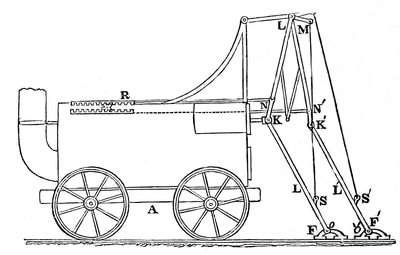
A sketch of these propellers is given in fig. 53. A is the carriage moving on the railroad, L and L´ are the legs, F and F´ the feet. The foot F has a joint at O, which corresponds to the ankle; another joint is placed at K, which corresponds to the knee; and a third is placed at L, which corresponds to the hip. Similar joints are placed at the corresponding letters in the other leg. The knee-joint K is attached to the end of the piston of the cylinder. When the piston, which is horizontal, is pressed outwards, the leg L presses the foot F against the ground, and the resistance forces the carriage A onwards. As the carriage proceeds, the angle K at the knee becomes larger, so that the leg and thigh take a straighter position; and this continues until the piston has reached the end of its stroke. At the hip L there is a short lever, L M, the extremity of which is connected by a cord or chain with a point, S, placed near the shin of the leg. When the piston is pressed into the cylinder, the knee, K, is drawn towards the engine, and the cord, M S, is made to lift the foot, F, from the ground; to which it does not return until the piston has arrived at the extremity of the cylinder. On the piston being again driven out of the cylinder, the foot, F, being placed on the road, is pressed backwards by the force of the piston-rod at K; but the friction of the ground preventing its backward motion, the re-action causes the engine to advance: and in the same manner this process is continued.
Attached to the thigh, at N, above the knee, by a joint, is a horizontal rod, N R, which works a rack, R. This rack has beneath it a cog-wheel. This cog-wheel acts in another rack below it. By these means, when the knee K is driven from the engine, the rack R is moved backwards; but the cog-wheel, acting on the other rack beneath it, will move the latter in the contrary direction. The rack R being then moved in the same direction with the knee, K, it follows that the other rack will always be moved in a contrary direction. The lower rack is connected by another horizontal rod with the thigh of the leg, L´ F´, immediately above the knee, at N´. When the piston is forced inwards, the knee, K´, will thus be forced backwards; and when the piston is forced outwards, the knee, K´, will be drawn forwards. It therefore follows that the two knees, K and K´, are pressed alternately backwards and forwards. The foot, F´, when the knee, K´, is drawn forward, is lifted by the means already described for the foot, F.
It will be apparent, from this description, that the piece of mechanism here exhibited is a contrivance derived from the motion of the legs of an animal, and resembling in all respects the fore legs of a horse. It is however to be regarded rather as a specimen of great ingenuity than as a contrivance of practical utility.
In 1814, an engine was constructed at Killingworth, by Mr. Stephenson, having two cylinders with a cylindrical boiler, and working two pair of wheels, by cranks placed at right angles; so that when the one was in full operation, the other was at its dead points. By these means the propelling power was always in action. The cranks were maintained in this position by an endless chain, which passed round two cogged wheels placed under the engine, and which were fixed on the same axles on which the wheels were placed. The wheels in this case were fixed on the axles, and turned with them.
Fig. 54.
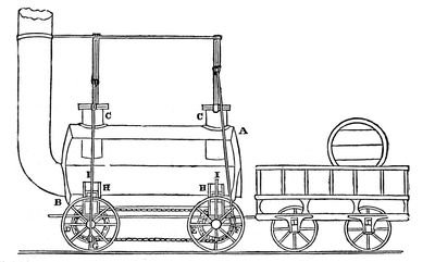
This engine is represented in fig. 54., the sides being open, to render the interior mechanism visible. A B is the cylindrical boiler; C C are the working cylinders; D E are the cogged wheels fixed on the axle of the wheels of the engine, and surrounded by the endless chain. These wheels being equal in magnitude, perform their revolutions in the same time; so that, when the crank, F, descends to the lowest point, the crank, G, rises from the lowest point to the horizontal position, D; and, again, when the crank, F, rises from the lowest point to the horizontal position, E, the other crank rises to the highest point; and so on. A very beautiful contrivance was adopted in this engine, by which it was suspended on springs of steam. Small cylinders, represented at H, are screwed by flanges to one side of the boiler, and project within it a few inches; they have free communication at the top with the water or steam of the boiler. Solid pistons are represented at I, which move steam-tight in these cylinders; the cylinders are open at the bottom, and the piston-rods are screwed on the carriage of the engine, over the axle of each pair of wheels, the pistons being presented upwards. As the engine is represented in the figure, it is supported on four pistons, two at each side. The pistons are pressed upon by the water or steam which occupies the upper chamber of the cylinder; and the latter being elastic in a high degree, the engine has all the advantage of spring suspension. The defect of this method of supporting the engine is, that when the steam loses that amount of elasticity necessary for the support of the machine, the pistons are forced into the cylinders, and the bottoms of the cylinders bear upon them. All spring suspension is then lost. This mode of suspension has consequently since been laid aside.
In an engine subsequently constructed by Mr. Stephenson, for the Killingworth railroad, the mode adopted of connecting the wheels by an endless chain and cog-wheels was abandoned; and the same effect was produced by connecting the two cranks by a straight rod. All such contrivances, however, have this great defect, that, if the fore and hind wheels be not constructed with dimensions accurately equal, there must necessarily be a slipping or dragging on the road. The nature of the machinery requires that each wheel should perform its revolution exactly in the same time; and consequently, in doing so, must pass over exactly equal lengths of the road. If, therefore, the circumference of the wheels be not accurately equal, that wheel which has the lesser circumference must be dragged along so much of the road as that by which it falls short of the circumference of the greater wheel; or, on the other hand, the greater must be dragged in the opposite direction, to compensate for the same difference. As no mechanism can accomplish a perfect equality in four, much less in six, wheels, it may be assumed that a great portion of that dragging effect is a necessary consequence of the principle of this machine; and even were the wheels, in the first instance, accurately constructed, it is not possible that their wear could be so exactly uniform as to continue equal.
(87.) The next stimulus which the progress of this invention received, proceeded from the great national work undertaken at Liverpool, by which that town and the extensive commercial mart of Manchester were connected by a double line of railway. When this project was undertaken, it was not decided what moving power it might be most expedient to adopt as a means of transport on the proposed road: the choice lay between horse-power, fixed steam engines, and locomotive engines; but the first, for many obvious reasons, was at once rejected in favour of one or other of the last two.
The steam engine may be applied, by two distinct methods, to move wagons either on a turnpike road or on a railway. By the one method the steam engine is fixed, and draws the carriage or train of carriages towards it by a chain extending the whole length of road on which the engine works. By this method the line of road over which the transport is conducted is divided into a number of short intervals, at the extremity of each of which an engine is placed. The wagons or carriages, when drawn by any engine to its own station, or detached, and connected with the extremity of the chain worked by the next stationary engine; and thus the journey is performed, from station to station, by separate engines. By the other method the same engine draws the load the whole journey, travelling with it.
The Directors of the Liverpool and Manchester railroad, when that work was advanced towards its completion, employed, in the spring of the year 1829, Messrs. Stephenson and Lock and Messrs. Walker and Rastrick, experienced engineers, to visit the different railways where practical information respecting the comparative effects of stationary and locomotive engines was likely to be obtained; and from these gentlemen they received reports on the relative merits, according to their judgment, of the two methods. The particulars of their calculations are given at large in the valuable work of Mr. Nicholas Wood on railways; to which we refer the reader, not only on this, but on many other subjects connected with the locomotive steam engine into which it would be foreign to our subject to enter. The result of the comparison of the two systems was, that the capital necessary to be advanced to establish a line of stationary engines was considerably greater than that which was necessary to establish an equivalent power in locomotive engines; that the annual expense by the stationary engines was likewise greater; and that, consequently, the expense of transport by the latter was greater, in a like proportion. The subjoined table exhibits the results numerically:—
Capital. Annual Expense. Expense of taking a Ton of Goods One Mile.
£ s. d. £ s. d.
Locomotive Engines 58,000 0 0 25,517 8 2 0·164 of a penny.
Stationary Engines 121,496 7 0 42,031 16 5 0·269
Locomotive System—less 63,496 7 0 16,514 8 3 0·105
On the score of economy, therefore, the system of locomotive engines was entitled to a preference; but there were other considerations which conspired with this to decide the choice of the Directors in its favour. An accident occurring in any part of a road worked by stationary engines must necessarily produce a total suspension of work along the entire line. The most vigilant and active attention on the part of every workman, however employed, in every part of the line, would therefore be necessary; but, independently of this, accidents arising from the fracture or derangement of any of the chains, or from the suspension of the working of any of the fixed engines, would be equally injurious, and would effectually stop the intercourse along the line. On the other hand, in locomotive engines an accident could only affect the particular train of carriages drawn by the engine to which the accident might occur; and even then the difficulty could be remedied by having a supply of spare engines at convenient stations along the line. It is true that the probability of accident is, perhaps, less in the stationary than in the locomotive system; but the injurious consequences, when accident does happen, are prodigiously greater in the former. "The one system," says Mr. Walker, "is like a chain extending from Liverpool to Manchester, the failure of a single link of which would destroy the whole; while the other is like a number of short and unconnected chains," the destruction of any one of which does not interfere with the effect of the others, and the loss of which may be supplied with facility.
The decision of the Directors was, therefore, in favour of locomotive engines; and their next measure was to devise some means by which the inventive genius of the country might be stimulated to supply them with the best possible form of engines for this purpose. With this view, it was proposed and carried into effect to offer a prize for the best locomotive engine which might be produced under certain proposed conditions, and to appoint a time for a public trial of the claims of the candidates. A premium of 500l. was accordingly offered for the best locomotive engine to run on the Liverpool and Manchester Railway; under the condition that it should produce no smoke; that the pressure of the steam should be limited to 50 lbs. on the inch; and that it should draw at least three times its own weight, at the rate of not less than ten miles an hour; that the engine should be supported on springs, and should not exceed fifteen feet in height. Precautions were also proposed against the consequences of the boiler bursting; and other matters, not necessary to mention more particularly here. This proposal was announced in the spring of 1829, and the time of trial was appointed in the following October. The engines which underwent the trial were, the Rocket, constructed by Mr. Stephenson; the Sanspariel, by Hackworth; and the Novelty, by Messrs. Braithwait and Ericson. Of these, the Rocket obtained the premium. A line of railway was selected for the trial, on a level piece of road about two miles in length, near a place called Rainhill, between Liverpool and Manchester; the distance between the two stations was a mile and a half, and the engine had to travel this distance backwards and forwards ten times, which made altogether a journey of 30 miles. The Rocket performed this journey twice: the first time in 2 hours 14 minutes and 8 seconds; and the second time, in 2 hours 6 minutes and 49 seconds. Its speed at different parts of the journey varied: its greatest rate of motion was rather above 29 miles an hour; and its least, about 11-1/2 miles an hour. The average rate of the one journey was 13-4/10 miles an hour; and of the other, 14-2/20 miles. This was the only engine which performed the complete journey proposed, the others having been stopped from accidents which occurred to them in the experiment. The Sanspariel performed the distance between the stations eight times, travelling 22-1/2 miles in 1 hour 37 minutes and 16 seconds. The greatest velocity to which this engine attained was something less than 23 miles per hour. The Novelty had only passed twice between the stations when the joints of the boiler gave way, and put an end to the experiment.
(88.) The great object to be attained in the construction of these engines was, to combine with sufficient lightness the greatest possible heating power. The fire necessarily acts on the water in two ways: first, by its radiant heat; and, second, by the current of heated air which is carried by the draft through the fire, and finally passes into the chimney. To accomplish this object, therefore, it is necessary to expose to both these sources of heat the greatest possible quantity of surface in contact with the water. These ends were attained by the following admirable arrangement in the Rocket:—
Fig. 55.
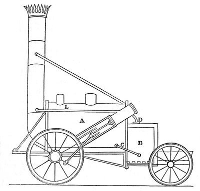
Fig. 56.
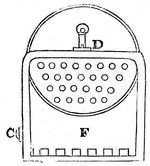
This engine is represented in fig. 55. It is supported on four wheels; the principal part of the weight being thrown on one pair, which are worked by the engine. The boiler consists of a cylinder 6 feet in length, with flat ends; the chimney issues from one end, and to the other end is attached a square box, B, the bottom of which is furnished with the grate on which the fuel is placed. This box is composed of two casings of iron, one contained within the other, having between them a space about 3 inches in breadth; the magnitude of the box being 3 feet in length, 2 feet in width, and 3 feet in depth. The casing which surrounds the box communicates with the lower part of the boiler by a pipe marked C; and the same casing at the top of the box communicates with the upper part of the boiler by another pipe marked D. When water is admitted into the boiler, therefore, it flows freely through the pipe C, into the casing which surrounds the furnace or fire-box, and fills this casing to the same level as that which it has in the boiler. When the engine is at work, the boiler is kept about half filled with water; and, consequently, the casing surrounding the furnace is completely filled. The steam which is generated in the water contained in the casing finds its exit through the pipe D, and escapes into the upper part of the boiler. A section of the engine, taken at right angles to its length is represented at fig. 56. Through the lower part of the boiler pass a number of copper tubes of small size, which communicate at one end with the fire-box, and at the other with the chimney, and form a passage for the heated air from the furnace to the chimney. The ignited fuel spread on the grate at the bottom of the fire-box disperses its heat by radiation, and acts in this manner on the whole surface of the casing surrounding the fire-box; and thus raises the temperature of the thin shell of water contained in that casing. The chief part of the water in the casing, being lower in its position than the water in the boiler, acquires a tendency to ascend when heated, and passes into the boiler; so that a constant circulation of the heated water is maintained, and the water in the boiler must necessarily be kept at nearly the same temperature as the water in the casing. The air which passes through the burning fuel, and which fills the fire-box, is carried by the draft through the tubes which extend through the lower part of the boiler; and as these tubes are surrounded on every side with the water contained in the boiler, this air transmits its heat through these tubes to the water. It finally issues into the chimney, and rises by the draft. The power of this furnace must necessarily depend on the power of draft in the chimney; and to increase this, and at the same time to dispose of the waste steam after it has worked the piston, this steam is carried off by a pipe L, which passes from the cylinder to the chimney, and escapes there in a jet which is turned upwards. By the velocity with which it issues from this jet, and by its great comparative levity, it produces a strong current upwards in the chimney, and thus gives force to the draft of the furnace. In fig. 56. the grate-bars are represented at the bottom of the fire-box at F. There are two cylinders, one of which works each wheel; one only appearing in the drawing, fig. 55., the other being concealed by the engine. The spokes which these cylinders work are placed at right angles on the wheels; the wheels being fixed on a common axle, with which they turn.
In this engine, the surface of water surrounding the fire-box, exposed to the action of radiant heat, amounted to 20 square feet, which received heat from the surface of 6 square feet of burning fuel on the bars. The surface exposed to the action of the heated air amounted to 118 square feet. The engine drew after it another carriage, containing fuel and water; the fuel used was coke, for the purpose of avoiding the production of smoke.
(89.) The Sanspareil of Mr. Hackworth is represented in fig. 57.; the horizontal section being exhibited in fig. 58.
Fig. 57.
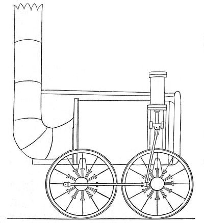
Fig. 58.
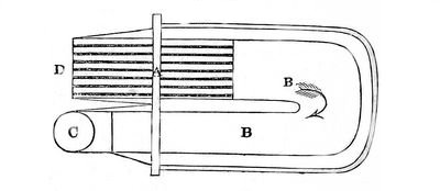
The draft of the furnace is produced in the same manner as in the Rocket, by ejecting the waste steam coming from the cylinder into the chimney; the boiler, however, differs considerably from that of the Rocket. A recurved tube passes through the boiler, somewhat similar to that already described in the early engine of Messrs. Trevithick and Vivian. In the horizontal section (fig. 58.), D expresses the opening of the furnace at the end of the boiler, beside the chimney. The grate-bars appear at A, supporting the burning fuel; and a curved tube passing through the boiler, and terminating in the chimney, is expressed at B, the direction of the draft being indicated by the arrow; C is a section of the chimney. The cylinders are placed, as in the Rocket, on each side of the boiler; each working a separate wheel, but acting on spokes placed at right angles to each other. The tube in which the grate and flue are placed diminishes in diameter as it approaches the chimney. At the mouth where the grate was placed, its diameter was 2 feet; and it was gradually reduced, so that, at the chimney, its diameter was only 15 inches. The grate-bars extended 5 feet into the tube. The surface of water exposed to the radiant heat of the fire was 16 square feet; and that exposed to the action of the heated air and flame was about 75 square feet. The magnitude of the grate or sheet of burning fuel which radiated heat, was 10 square feet.
(90.) The Novelty, of Messrs. Braithwait and Ericson, is represented in fig. 59.; and a section of the generator and boiler is exhibited in fig. 60.: the corresponding parts in the two figures are marked by the same letters.
Fig. 59.
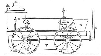
A is the generator or receiver, containing the steam which works the engine; this communicates with a lower generator, B, which extends in a horizontal direction the entire length of the carriage. Within the generator, A, is contained the furnace, F, which communicates in a tube, C; carried up through the generator, and terminated at the top by sliding shutters, which exclude the air, and which are only opened to supply fuel to the grate, F. Below the grate the furnace is not open, as usual, to the atmosphere, but communicates by a tube, E, with a bellows, D; which is worked by the engine, and which forces a constant stream of air, by the tube E, through the fuel on F, so as to keep that fuel in vivid combustion. The heated air, contained in the furnace, F, is driven on, by the same force, through a small curved tube marked e, which circulates like a worm (as represented in fig. 60.) through the horizontal generator or receiver; and, tapering gradually, until reduced to very small dimensions, it finally issues into the chimney, G. The air, in passing along this tube, imparts its heat to the water by which the tube is surrounded, and is brought to a considerably reduced temperature when discharged into the chimney. The cylinder, which is represented at K, works one pair of wheels, by means of a bell-crank; the other pair, when necessary, being connected with them.
Fig. 60.
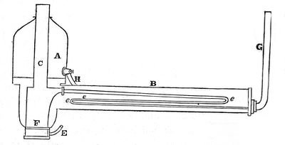
In this engine, the magnitude of the surface of burning fuel on the grate-bars is less than 2 square feet; the surface exposed to radiant heat is 9-1/2 square feet; and the surface of water exposed to heated air is about 33 square feet.
(91.) The great object to be effected in the boilers of these engines is, to keep a small quantity of water at an excessive temperature, by means of a small quantity of fuel kept in the most active state of combustion. To accomplish this, it is necessary, first, so to shape the boiler, furnace, and flues, that the water shall be in contact with as extensive a surface as possible, every part of which is acted on either immediately, by the heat radiating from the fire, or mediately, by the air which has passed through the fire, and which finally rushes into the chimney: and, secondly, that such a forcible draught should be maintained in the furnace, that a quantity of heat shall be extricated from the fuel, by combustion, sufficient to maintain the water at the necessary temperature, and to produce the steam with sufficient rapidity. To accomplish these objects, therefore, the chamber containing the grate should be completely surrounded by water, and should be below the level of the water in the boiler. The magnitude of the surface exposed to radiation should be as great as is consistent with the whole magnitude of the machine. The comparative advantage which the Rocket possessed in these respects over the other engines will be evident on inspection. In the next place, it is necessary that the heat, which is absorbed by the air passing through the fuel, and keeping it in a state of combustion, should be transferred to the water before the air escapes into the chimney. Air being a bad conductor of heat, to accomplish this it is necessary that the air in the flues should be exposed to as great an extent of surface in contact with the water as possible. No contrivance can be less adapted for the attainment of this end than one or two large tubes traversing the boiler, as in the earliest locomotive engines: the body of air which passes through the centre of these tubes had no contact with their surface, and, consequently, passed into the chimney at nearly the same temperature as that which it had when it quitted the fire. The only portion of air which imparted its heat to the water was that portion which passed next to the surface of the tube.
Several methods suggest themselves to increase the surface of water in contact with a given quantity of air passing through it. This would be accomplished by causing the air to pass between plates placed near each other, so as to divide the current into thin strata, having between them strata of water, or it might be made to pass between tubes differing slightly in diameter, the water passing through an inner tube, and being also in contact with the external surface of the outer tube. Such a method would be similar in principle to the steam-jacket used in Watt's steam engines, or to the condenser of Cartwright's engine already described. But, considering the facility of constructing small tubes, and of placing them in the boiler, that method, perhaps, is, on the whole, the best in practice; although the shape of a tube, geometrically considered, is most unfavourable for the exposure of a fluid contained in it to its surface. The air which passes from the fire-chamber, being subdivided as it passes through the boiler by a great number of very small tubes, may be made to impart all its excess of heat to the water before it issues into the chimney. This is all which the most refined contrivance can effect. The Rocket engine was traversed by 25 tubes, each 3 inches in diameter; and the principle has since been carried to a much greater extent.
The abstraction of a great quantity of heat from the air before it reaches the chimney is attended with one consequence, which, at first view, would present a difficulty apparently insurmountable; the chimney would, in fact, lose its power of draught. This difficulty, however, was removed by using the waste steam, which had passed from the cylinder after working the engine, for the purpose of producing a draught. This steam was urged through a jet presented upwards in the chimney, and driven out with such force in that direction as to create a sufficient draught to work the furnace.
It will be observed that the principle of draught in the Novelty is totally distinct from this: in that engine the draught is produced by a bellows worked by the engine. The question, as far as relates to these two methods, is, whether more power is lost in supplying the steam through the jet, as in the Rocket, or in working the bellows, as in the Novelty. The force requisite to impel the steam through the jet must be exerted by the returning stroke of the piston, and, consequently, must rob the working effect to an equivalent amount. On the other hand, the power requisite to work the bellows in the Novelty must be subducted from the available power of the engine. The former method is found to be the more effectual and economical.
The importance of these details will be understood, when it is considered that the only limit to the attainment of speed by locomotive engines is the power to produce in a given time a certain quantity of steam. Each stroke of the piston causes one revolution of the wheels, and consumes two cylinders full of steam: consequently, a cylinder of steam corresponds to a certain number of feet of road travelled over: hence it is that the production of a rapid and abundant supply of heat, and the imparting of that heat quickly and effectually to the water, is the key to the solution of the problem to construct an engine capable of rapid motion.
The method of subdividing the flue into tubes was carried much further by Mr. Stephenson after the construction of the Rocket; and, indeed, the principle was so very obvious, that it is only surprising that, in the first instance, tubes of smaller diameter than 3 inches were not used. In engines since constructed, the number of tubes vary from 90 to 120, the diameter being reduced to 2 inches or less, and in some instances tubes have been introduced, even to the number of 150, of 1-1/2 inch diameter. In the Meteor, 20 square feet are exposed to radiation, and 139 to the contact of heated air; in the Arrow, 20 square feet to radiation, and 145 to the contact of heated air. The superior economy of fuel gained by this means will be apparent by inspecting the following table, which exhibits the consumption of fuel which was requisite to convey a ton weight a mile in each of four engines, expressing also the rate of the motion:—
Engines. Average rate of speed in miles per hour. Consumption of Coke in pounds per ton per mile.
No. 1. Rocket 14 2·41
2. Sanspareil 15 2·47
3. Phœnix 12 1·42
4. Arrow 12 1·25
(92.) Since the period at which the railway was opened for the actual purposes of transport, the locomotive engines have been in a state of progressive improvement. Scarcely a month has passed without suggesting some change in the details, by which fuel might be economised, the production of steam rendered more rapid, the wear of the engine rendered slower, the proportionate strength of the different parts improved, or some other desirable end obtained. The consequence of this has been, that the particular engines to which we have alluded, and others of the same class, without having, as it were, lived their natural life, or without having been worn out by work, have been laid aside to give place to others of improved powers. By the exposure of the cylinders to the atmosphere in the Rocket, and engines of a similar form, a great waste of heat was incurred, and it was accordingly determined to remove them from the exterior of the boiler, and to place them within a casing immediately under the chimney: this chamber was necessarily kept warm by its proximity to the end of the boiler, but more by the current of heated air which constantly rushed into it from the tubes. This change, also, rendered necessary another, which improved the working of the engine. In the earlier engines the motion of the piston was communicated to the wheel by a connecting rod attached to one of the spokes on the exterior of the wheel, as represented in fig. 55. By the change to which we have just alluded, the cylinders being placed between the wheels under the chimney, this mode of working became inapplicable, and it was considered better to connect the piston-rods with two cranks placed at right angles on the axles of the great wheels. By this means, it was found that the working of the machine was more even, and productive of less strain than in the former arrangement. On the other hand, a serious disadvantage was incurred by the adoption of a cranked axle. The weakness necessarily arising from such a form of axle could only be counterbalanced by great thickness and weight of metal; and even this precaution does not prevent the occasional fracture of such axles at the angles of the cranks. The advantages, however, of this plan, on the whole, are considered to predominate.
In the most improved engines in present use two safety-valves are provided, of which only one is in the power of the engine-man. The tubes being smaller and more numerous than in the earlier engines, the heat is more completely extracted from the air before it enters the chimney. A powerful draft is rendered still more necessary by the smallness of the tubes: this is effected by forcing the steam which has worked the pistons through a contracted orifice, presented upwards in the chimney, by the regulation of which any degree of draft may be obtained.
One of the most improved engines at present in use is represented in fig. 61.
A represents the cylindrical boiler, the lower half of which is traversed by tubes, as described in the Rocket. They are usually from 80 to 100 in number, and about 1-1/2 inch in diameter; the boiler is about 7 feet in length; the fire-chamber is attached to one end of it, at F, as in the Rocket, and similar in construction; the cylinders are inserted in a chamber at the other end, immediately under the chimney. The piston-rods are supported in the horizontal position by guides; and connecting rods extend from them, under the engine, to the two cranks placed on the axle of the large wheels. The effects of any inequality in the road are counteracted by springs, on which the engine rests; the springs being below the axle of the great wheels, and above that of the less. The steam is supplied to the cylinders, and withdrawn, by means of the common sliding valves, which are worked by an eccentric wheel placed on the axle of the large wheels of the carriage. The motion is communicated from this eccentric wheel to the valve by sliding rods. The stand is placed for the attendant at the end of the engine, next the fire-place, F; and two levers, L, project from the end, which communicate with the valves by means of rods, by which the engine is governed, so as to stop or reverse the motion.
Fig. 61.
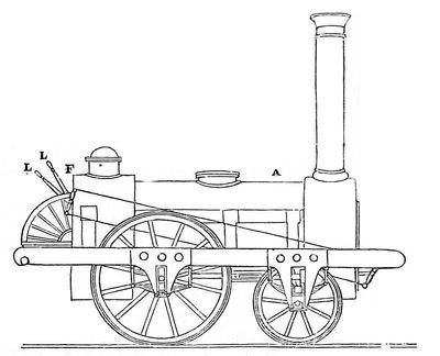
The wheels of these engines have been commonly constructed of wood, with strong iron tires, furnished with flanges adapted to the rails. But Mr. Stephenson has recently substituted, in some instances, wheels of iron with hollow spokes. The engine draws after it a tender carriage containing the fuel and water; and, when carrying a light load, is capable of performing the whole journey from Liverpool to Manchester without a fresh supply of water. When a heavy load of merchandise is drawn, it is usual to take in water at the middle of the trip.
The successive introduction of improvements in the engines, some of which we have mentioned, has been accompanied by corresponding accessions to their practical power, and to the economy of fuel; and they have now arrived at a point which is as far beyond the former expectations of the most sanguine locomotive projectors, as it assuredly is short of the perfection of which these wonderful machines are still susceptible.
In the spring of the year 1832, I made several experiments on the Manchester railway, with a view to determine, in the actual state of the locomotive engines at that time, their powers with respect to the amount of load and the economy of fuel. Since that time I am not aware that, in these respects, the engine has received any material improvement. The following are the particulars of three experiments thus made:—
I.
On Saturday, the 5th of May, the engine called the "Victory" took 20 wagons of merchandise, weighing gross 92 tons 19 cwt. 1 qr., together with the tender containing fuel and water, of the weight of which I have no account, from Liverpool to Manchester (30 miles,) in 1 h. 34 min. 45 sec. The train stopped to take in water half-way, for 10 minutes, not included in the above mentioned time. On the inclined plane rising 1 in 96, and extending 1-1/2 mile, the engine was assisted by another engine called the "Samson," and the ascent was performed in 9 minutes. At starting, the fire-place was well filled with coke, and the coke supplied to the tender accurately weighed. On arriving at Manchester the fire-place was again filled, and the coke remaining in the tender weighed. The consumption was found to amount to 929 pounds net weight, being at the rate of one third of a pound per ton per mile.
Speed on the level was 18 miles an hour; on a fall of 4 feet in a mile, 21-1/2 miles an hour; fall of 6 feet in a mile, 25-1/2 miles an hour; on the rise over Chatmoss, 8 feet in a mile 17-5/8 miles an hour; on level ground sheltered from the wind, 20 miles an hour. The wind was moderate, but direct ahead. The working wheels slipped three times on Chatmoss, and the train was retarded from 2 to 3 minutes.
The engine, on this occasion, was not examined before or after the journey, but was presumed to be in good working order.
II.
On Tuesday, the 8th of May, the same engine performed the same journey, with 20 wagons, weighing gross 90 tons 7 cwt. 2 qrs., exclusive of the unascertained weight of the tender. The time of the journey was 1 h. 41 min. The consumption of coke 1040 lbs. net weight, estimated as before. Rate of speed:—
Level 17-5/8 miles per hour.
Fall of 4 feet in a mile 22
—— 6 22-1/2
Rise of 8 15
On this occasion there was a high wind ahead on the quarter, and the connecting rod worked hot, owing to having been keyed too tight. On arriving at Manchester, I caused the cylinders to be opened, and found that the pistons were so loose, that the steam blew through the cylinders with great violence. By this cause, therefore, the machine was robbed of a part of its power during the journey; and this circumstance may explain the slight decrease in speed, and increase in the consumption of fuel, with a lighter load in this journey compared with that performed on the 5th of May.
The Victory weighs 8 tons 2 cwt., of which 5 tons 4 cwt. rest on the drawing wheels. The cylinders are 11 inches diameter, and 16 inches stroke; and the diameter of the drawing wheels is 5 feet.
III.
On the 29th of May, the engine called the "Samson," (weighing 10 tons 2 cwt., with 14-inch cylinders, and 16-inch stroke; wheels 4 feet 6 inches diameter, both pairs being worked by the engine; steam 50 lbs. pressure, 130 tubes) was attached to 50 wagons, laden with merchandise; net weight about 150 tons; gross weight, including wagons, tender, &c., 223 tons 6 cwt. The engine with this load travelled from Liverpool to Manchester (30 miles) in 2 h. and 40 min., exclusive of delays upon the road for watering, &c., being at the rate of nearly 12 miles an hour. The speed varied according to the inclinations of the road. Upon a level, it was 12 miles an hour; upon a descent of 6 feet in a mile, it was 16 miles an hour: upon a rise of 8 feet in a mile, it was about 9 miles an hour. The weather was calm, the rails very wet; but the wheels did not slip, even in the slowest speed, except at starting, the rails being at that place soiled and greasy with the slime and dirt to which they are always exposed at the stations. The coke consumed in this journey, exclusive of what was raised in getting up the steam, was 1762 lbs., being at the rate of a quarter of a pound per ton per mile.
(94.) From the above experiments it appears that a locomotive engine, in good working order, with its full complement of load, is capable of transporting weights at an expense in fuel amounting to about 4 ounces of coke per ton per mile. The attendance required on the journey is that of an engine-man and a fire-boy; the former being paid 1s. 6d. for each trip of 30 miles, and the latter 1s. In practice, however, we are to consider, that it rarely happens that the full complement of load can be sent with the engines; and when lesser loads are transported, the proportionate expense must for obvious reasons, be greater.
The practical expenditure of fuel on the Liverpool and Manchester line may, perhaps, be fairly estimated at half a pound of coke per ton per mile.
(95.) Having explained the power and efficiency of these locomotive engines, it is now right to notice some of the defects under which they labour.
The great original cost, and the heavy expense of keeping the engines used on the railway in repair, have pressed severely on the resources of the undertaking. One of the best constructed of the later engines costs originally about 800l. It may be hoped that, by the excitement of competition, the facilities derived from practice, and from the manufacture of a greater number of engines of the same kind, some reduction of this cost may be effected. The original cost, however, is far from being the principal source of expense: the wear and tear of these machines, and the occasional fracture of those parts on which the greatest strain has been laid, have greatly exceeded what the directors had anticipated. Although this source of expense must be in part attributed to the engines not having yet attained that state of perfection, in the proportion and adjustment of their parts, of which they are susceptible, and to which experience alone can lead, yet there are some obvious defects which demand attention.
The heads of the boilers are flat, and formed of iron, similar to the material of the boilers themselves. The tubes which traverse the boiler were, until recently, copper, and so inserted into the flat head or ends as to be water-tight. When the boiler is heated, the tubes are found to expand in a greater degree than the other parts of the boiler; which frequently causes them either to be loosened at the extremities, so as to cause leakage, or to bend from want of room for expansion. The necessity of removing and refastening the tubes causes, therefore, a constant expense.
It will be recollected that the fire-place is situated at one end of the boiler, immediately below the mouths of the tubes: a powerful draught of air, passing through the fire, carries with it ashes and cinders, which are driven violently through the tubes, and especially the lower ones, situated near the fuel. These tubes are, by this means, subject to rapid wear, the cinders continually acting upon their interior surface. After a short time it becomes necessary to replace single tubes, according as they are found to be worn, by new ones; and it not unfrequently happens, when this is neglected, that tubes burst. After a certain length of time the engines require new tubing, which is done at the expense of about 70l., allowing for the value of the old tubes. This wear of the tubes might possibly be avoided by constructing the fire-place in a lower position, so as to be more removed from their mouths; or, still more effectually, by interposing a casing of metal, which might be filled with water, between the fire-place and those tubes which are the most exposed to the cinders and ashes. The unequal expansion of the tubes and boilers appears to be an incurable defect, if the present form of the engine be retained. If the fire-place and chimney could be placed at the same end of the boiler, so that the tubes might be recurved, the unequal expansion would then produce no injurious effect; but it would be difficult to clean the tubes if they were exposed, as they are at present, to the cinders. The next source of expense arises from the wear of the boiler-head, which is exposed to the action of the fire. These require constant patching and frequent renewal.
A considerable improvement has lately been introduced into the method of tubing, by substituting brass for copper tubes. We are not aware that the cause of this improvement has been discovered; but it is certain, whatever be the cause, that brass tubes are subject to considerably slower wear than copper.
It has been said by some whose opinions are adverse to the advantage of railways, but more especially to the particular species of locomotive engines now under consideration, that the repairs of one of these engines cost so great a sum as 1500l. per annum, and that the directors now think of abandoning them, or adopting either stationary engines or horse-power. As to the first of these statements I must observe, that the expense of repairs of such machines should never be computed in reference to time, but rather to the work done, or the distance travelled over. I have ascertained that engines frequently travel a distance of from 25,000 to 30,000 miles before they require new tubing. During that work, however, single tubes are, of course, occasionally renewed, and other repairs are made, the expense of which may safely be stated as under the original cost of the engine. The second statement, that the company contemplate substituting stationary engines, or horses, for locomotives, is altogether at variance with the truth. Whatever improvements may be contemplated in locomotives, the directors assuredly have not the slightest intention of going back in the progress of improvement, in the manner just mentioned.
The expense of locomotive power having so far exceeded what was anticipated at the commencement of the undertaking, it was thought advisable, about the beginning of the year 1834, to institute an inquiry into the causes which produced the discrepancy between the estimated and actual expenses, with a view to the discovery of some practical means by which they could be reduced. The directors of the company, for this purpose, appointed a sub-committee of their own body, assisted by Mr. Booth, their treasurer, to inquire and report respecting the causes of the amount of this item of their expenditure, and to ascertain whether any and what measures could be devised for the attainment of greater economy. A very able and satisfactory report was made by this committee, or, to speak more correctly by Mr. Booth.
It appears that, previous to the establishment of the railway, Messrs. Walker and Rastrick, engineers, were employed by the company to visit various places where steam power was applied on railways, for the purpose of forming an estimate of the probable expense of working the railway by locomotive and by fixed power. These engineers recommended the adoption of locomotive power, and their estimate was, that the transport might be effected at the rate of .278 of a penny, or very little more than a farthing per ton per mile. In the year 1833, five years after this investigation took place, it was found that the actual cost was .625 of a penny, or something more than a halfpenny per ton per mile, being considerably above double the estimated rate. Mr. Booth very properly directed his inquiries to ascertain the cause of this discrepancy, by comparing the various circumstances assumed by Messrs. Walker and Rastrick, in making their estimate, with those under which the transport was actually effected. The first point of difference which he observed was the speed of transport: the estimate was founded on an assumed speed of ten miles an hour, and it was stated that a fourfold speed would require an addition of 50 per cent. to the power, without taking into account wear and tear. Now the actual speed of transport being double the speed assumed in the statement, Mr. Booth holds it to be necessary to add 25 per cent. on that score.
The next point of difference is in the amount of the loads: the estimate is founded upon the assumption, that every engine shall start with its full complement of load, and that with this it shall go the whole distance. "The facts, however, are," says Mr. Booth, "that, instead of a full load of profitable carriage from Manchester, about half the wagons come back empty, and, instead of the tonnage being conveyed the whole way, many thousand tons are conveyed only half the way; also, instead of the daily work being uniform, it is extremely fluctuating." It is further remarked, that in order to accomplish the transport of goods from the branches and from intermediate places, engines are despatched several times a day, from both ends of the line, to clear the road; the object of this arrangement being rather to lay the foundation of a beneficial intercourse in future, than with a view to any immediate profit. Mr. Booth makes a rough estimate of the disadvantages arising from these circumstances by stating them at 33 per cent. in addition to the original estimate.
The next point of difference is the fuel. In the original estimate coal is assumed as the fuel, and it is taken at the price of five shillings and tenpence per ton: now the act of parliament forbids the use of coal which would produce smoke; the company have, therefore, been obliged to use coke, at seventeen shillings and sixpence a ton. Taking coke, then, to be equivalent to coal, ton for ton, this would add .162 to the original estimate.
These several discrepancies being allowed for, and a proportional amount being added to the original estimate, the amount would be raised to .601 of a penny per ton per mile, which is within one fortieth of a penny of the actual cost. This difference is considered to be sufficiently accounted for by the wear and tear produced by the very rapid motion, more especially when it is considered that many of the engines were constructed before the engineer was aware of the great speed that would be required.
"What then," says Mr. Booth, in the Report already alluded to, "is the result of these opposite and mutually counteracting circumstances? and what is the present position of the company in respect of their moving power? Simply, that they are still in a course of experiment, to ascertain practically the best construction, and the most durable materials, for engines required to transport greater weights, and at greater velocities, than had, till very recently, been considered possible; and which, a few years ago, it had not entered into the imagination of the most daring and sanguine inventor to conceive: and, farther, that these experiments have necessarily been made, not with the calm deliberation and quiet pace which a salutary caution recommends,—making good each step in the progress of discovery before advancing another stage,—but amidst the bustle and responsibilities of a large and increasing traffic; the directors being altogether ignorant of the time each engine would last before it would be laid up as inefficient, but compelled to have engines, whether good or bad; being aware of various defects and imperfections, which it was impossible at the time to remedy, yet obliged to keep the machines in motion, under all the disadvantages of heavy repairs, constantly going on during the night, in order that the requisite number of engines might be ready for the morning's work. Neither is this great experiment yet complete; it is still going forward. But the most prominent difficulties have been in a great measure surmounted, and your committee conceive, that they are warranted in expecting, that the expenditure in this department will, ere long, be materially reduced, more especially when they consider the relative performances of the engines at the present time compared with what it was two years ago."
In the half year ending 31st December, 1831, the six best engines performed as follows:—
Miles.
Planet 9,986
Mercury 11,040
Jupiter 11,618
Saturn 11,786
Venus 12,850
Etna 8,764
———
Making in all 66,044
———
In the half year ending 31st December, 1833, the six best engines performed as follows:—
Miles.
Jupiter 16,572
Saturn 18,678
Sun 15,552
Etna 17,763
Ajax 11,678
Firefly 15,608
———
Making in all 95,851
———
Now since 7-1/2 pounds is very nearly the 300th part of a ton, it follows that if an inclination upon a railroad rises at the rate of 1 foot in 300, or, what is the same, 17-1/2 feet in a mile, such an acclivity will add 7-1/2 pounds per ton to the force of traction. This acclivity therefore would require a force of traction twice as great as a level. In like manner a rise of 35 feet in a mile would require three times the force of traction of a level, 52-1/2 feet in a mile four times that force, and so on. In fact, for every 7 feet in a mile which an acclivity rises, 3 pounds per ton will be added to the force of traction. If we would then ascertain the power necessary to pull a load up any given acclivity upon a railroad, we must first take 7-1/2 pounds as the force necessary to overcome the common resistance of the road, and then add 3 pounds for every 7 feet which the acclivity rises per mile. For example, suppose an acclivity to rise at the rate of 70 feet in a mile, the force of traction necessary to draw a ton up it would be thus calculated:—
Friction 7-1/2 lbs.
70 feet = 10 times 3 lbs. 30
———
Total force 37-1/2
It will be apparent, therefore, that if a railroad undulates by inclined planes, even of the most moderate inclinations, the propelling power to be used upon it must be of such a nature as to be capable of increasing its intensity in a great degree, according to the elevation of the planes which it has to encounter. A plane which rises 52-1/2 feet per mile presents to the eye scarcely the appearance of an ascent, and yet requires the power of traction to be increased in a fourfold proportion.
It is the property of animal power, that within certain limits its energy can be put forth at will, according to the exigency of the occasion; but the intensity of mechanical power, in the instance now considered, cannot so conveniently be varied, except indeed within narrow limits.
In the application of locomotive engines upon railways the difficulty arising from inclined planes has been attempted to be surmounted by several methods, which we shall now explain.
1. Upon arriving at the foot of the plane the load is divided, and the engine carries it up in several successive trips, descending the plane unloaded after each trip. The objection to this method is the delay which it occasions,—a circumstance which is incompatible with a large transport of passengers. From what has been stated, it would be necessary, when the engine is fully loaded on a level, to divide its load into four parts, to be successively carried up when the incline rises 52 feet per mile. This method has been practised in the transport of merchandise occasionally, when heavy loads were carried on the Liverpool and Manchester line, upon the Rainhill incline.
2. A subsidiary or assistant locomotive engine may be kept in constant readiness at the foot of each incline, for the purpose of aiding the different trains, as they arrive, in ascending. The objection to this mode is the cost of keeping such an engine with its boiler continually prepared, and its steam up. It would be necessary to keep its fire continually lighted, whether employed or not; otherwise, when the train would arrive at the foot of the incline, it should wait until the subsidiary engine was prepared for work. In cases where trains would start and arrive at stated times, this objection, however, would have less force. This method is at present generally adopted on the Liverpool and Manchester line. This method, however, cannot be profitably applied to planes of any considerable length.
3. A fixed steam engine may be erected on the crest of the incline, so as to communicate by ropes with the train at the foot. Such an engine would be capable of drawing up one or two trains together, with their locomotives, according as they would arrive, and no delay need be occasioned. This method requires that the fixed engine should be kept constantly prepared for work, and the steam continually up in the boiler. This expedient is scarcely compatible with a large transit of passengers, except at the terminus of a line.
4. In working on the level, the communication between the boiler and the cylinder in the locomotives may be so restrained by partially closing the throttle valve, as to cause the pressure upon the piston to be less in a considerable degree than the pressure of steam in the boiler. If under such circumstances a sufficient pressure upon the piston can be obtained to draw the load on the level, the throttle valve may be opened on approaching the inclined plane, so as to throw on the piston a pressure increased in the same proportion as the previous pressure in the boiler was greater than that upon the piston. If the fire be sufficiently active to keep up the supply of steam in this manner during the ascent, and if the rise be not greater in proportion than the power thus obtained, the locomotive will draw the load up the incline without further assistance. It is, however, to be observed, that in this case the load upon the engine must be less than the amount which the adhesion of its working wheels with the railroad is capable of drawing; for this adhesion must be adequate to the traction of the same load up the incline, otherwise whatever increase of power might be obtained by opening the throttle valve, the drawing wheels would revolve without causing the load to advance. This method has been generally practised upon the Liverpool and Manchester line in the transport of passengers; and, indeed, it is the only method yet discovered, which is consistent with the expedition necessary for that species of traffic. The objections to this method are, the necessity of maintaining a much higher pressure in the boiler than is sufficient for the purposes of the load upon more level parts of the line.
In the practice of this method considerable aid may be derived also by suspending the supply of feeding water during the ascent. It will be recollected that a reservoir of cold water is placed in the tender which follows the engine, and that the water is driven from this reservoir into the boiler by a forcing-pump, which is worked by the engine itself. This pump is so constructed that it will supply as much cold water as is equal to the evaporation, so as to maintain constantly the same quantity of water in the boiler. But it is evident, on the other hand, that the supply of this water has a tendency to check the rate of evaporation, since in being raised to the temperature of the water with which it mixes, it must absorb a considerable portion of the heat supplied by the fire. With a view to accelerate the production of steam, therefore, in ascending the inclines, the engine-man may suspend the action of the forcing-pump, and thereby stop the supply of cold water to the boiler; the evaporation will go on with increased rapidity, and the exhaustion of water produced by it will be repaid by the forcing-pump on the next level, or still more effectually on the next descending incline. Indeed the feeding pump may be made to act in descending an incline if necessary, when the action of the engine itself is suspended, and when the train descends by its own gravity, in which case it will perform the part of a brake upon the descending train.
This method, on railroads intended for passengers, may be successfully applied on inclines which do not exceed 18 feet in a mile; and, with a sacrifice of the expense of locomotive power, inclines so steep as 36 feet in a mile may be worked in this manner. As, however, the sacrifice is considerable, it will, perhaps, be always better to work the more steep inclines by assistant engines.
5. The mechanical connexion between the piston of the cylinder and the points of contact of the working wheels with the road may be so altered, upon arriving at the incline, as to give the piston a greater power over the working wheels. This may be done in an infinite variety of ways, but hitherto no method has been suggested sufficiently simple to be applicable in practice; and even were any means suggested which would accomplish this, unless the intensity of the impelling power were at the same time increased, it would necessarily follow that the speed of the motion would be diminished in exactly the same proportion as the power of the piston over the working wheels would be increased. Thus, on the inclined plane, which rises 55 feet per mile, upon the Liverpool line, the speed would be diminished to nearly one fourth of its amount upon the level.