PREFACE. (continued 2)
Reading edition
By the experiments made at Woolwich in March 1801, it is recommended, that when cylinder powder is used on service, the charges of field ordnance with round shot, shall be reduced to the usual quantities for case shot. The same experiments recommend, that the thickness or length of the wood bottom be varied, in order to change the position of the shot, and thereby save the bore; and that the paper cap which is usually thrown away on service, shall be put over the shot before it is introduced into the piece.
For charges for small arms see the word Cartridges.
Charges of French Guns in French Weights.
lbs.
24 Prs. 8 Siege
16 Prs. 5½
12 Prs. 4 Field ¼ less for Case Shot.
8 Prs. 2½
4 Prs. 1½
CHEVAUX DE FRIZE.—The body or beam of a chevaux de frize is generally made 9 feet long, and 6 inches square, and weighs 41 lbs. The spears are 33 in number, weighing 2 lb. each, are 5 feet long, and 1¼ inches square. They are placed 9½ inches asunder.
COMPOSITION.—For the composition of fuzes, portfires, tubes, carcasses, see those words.
Composition for Kitt. For Fire Balls, 1794.
lbs. lbs. oz.
Rosin 9 Rosin 5 8
Pitch 6 Sulphur 3 0
Beeswax 6 Allum powder 1 8
Tallow 1 Starch, ” 0 8
Saltpetre 4 6
Mealed powder 8 0
Linseed oil ¼ pint.
Oil of spike 1 pint.
Bengal Lights.
First Composition.
lbs. oz.
Saltpetre 7 0
Sulphur 1 12
Red orpiment 0 8
Second Composition.
lbs. oz.
Saltpetre 2 4
Sulphur 0 8
Antimony 0 4
Orpiment 0 1½
Light Balls.
Nitre 40 parts
Sulphur 15
Antimony 3
Pitch 3
This composition to be carefully fused, and cast into the shape of balls, which when cold will be sufficiently hard to be fired from a small mortar.
Composition for Suffocating Pots.
Sulphur 6 parts
Nitre 5
This composition when intimately mixed, to be rammed into wooden boxes, and primed in the usual way.
This composition will answer for fumigation.
Chinese or White Light.
Nitre from 50 to 60 parts
Sulphur 16 to 20
Antimony 5
Orpiment 8 to 10
For Smoke Balls.
lbs.
Corned powder 10
Saltpetre 2
Pitch 4
Seacoal 3
Tallow 1
For Fire Hoops, Fire Arrows, and Fire Lances.
lbs. oz.
Mealed powder 1 0
Saltpetre 3 0
Flour of sulphur 0 8
Linseed oil ½ pint.
Composition to fill cases for setting fire to Fascine Batteries.
lbs. oz.
Mealed powder 1 4
Saltpetre 6 0
Sulphur 1 8
All dry compositions must be well mixed; first by the hands, and then passed several times through fine hair sieves, that the ingredients may be thoroughly incorporated. In mixing compositions which require fire, the greatest precautions are necessary; particularly in those where gunpowder enters. The dry parts of the composition may in general be mixed together first, and put by degrees into the cauldron, while the other ingredients are fluid, being well stirred all the time of putting in. When the dry ingredients are inflammable, the cauldron must not only be taken off the fire, but the bottom must be dipt in water, to prevent the possibility of accidents while mixing them.
R. Lab.
CONVOYS.—A waggon with four horses occupies about sixteen paces; a mile will therefore hold about 117 waggons: but allowing a short distance between, each waggon in travelling, a mile may be said to contain 100 waggons. Waggons in convoy may travel from one to two miles per hour, according to the roads and other circumstances. A great object in convoys is to preserve the horses as much as possible from fatigue. For this purpose, if the convoy amounts to many hundred waggons, they must be divided into divisions of not more than 500 each. Should it consist of thousands, it will be adviseable to divide them into grand divisions, and then again into subdivisions of 500 each: by this means, and the time of departure being calculated by the following rules, each division may remain at rest, till just before its time of movement; and which will prevent the necessity of the latter part of a large convoy being harassed for a considerable time before its turn to move.
Rule 1. To find the time in which any number of waggons may be driven off: Divide the number of waggons by 100, and multiply by the time of travelling one mile.
Rule 2. To find the time in which any number of waggons will drive over any number of miles: To the time they take in driving off, add the time any one of the waggons takes to travel the distance.
The different divisions of the convoy should be numbered, and obliged each day to change the order of their marching.
Whenever the progress of a train of waggons is arrested by the breaking down of any one of them, or other delay, all the waggons in the rear of the stoppage, should immediately drive up into the first open space, to as great a number as the open space will hold; this keeps the convoy together and better under the care of the escort.
The escort for a convoy should be divided into front, center, and rear guards; beside the divisions for the flanks, which should never be beyond musquet shot, or at most 400 yards from each other. The whole escort, should never be so separated that they could not be collected in an hour. Under proper precautions against an enemy, a convoy of any size cannot travel more than five or seven miles per day.
Templehoft.
D ispart.—The dispart of a gun is the half difference between the diameter of the gun at the base ring, and at the swell of the muzzle. The general dispart of all guns is about the ¹/₅₆ part of their length. See the disparts of French and English guns under the word Tangent Scale.
Fig. 1.
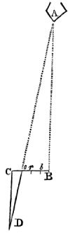
DISTANCES.—Inaccessible distances may be found several ways; the most correct of which of course is by means of proper mathematical instruments; which, however, are not always to be had in the field.
The following different methods are laid down by several authors, where instruments cannot be had.
I. Wishing to know the distance of the object A from B—(fig. 1.) place a picket at B and another at C, at a few fathoms distance, making A B C a right angle, and divide B C into 4, 5, or any number of equal parts: make another similar angle at C, in a direction from the object, and walk along the line C D till you bring yourself in a line with the object A, and any of the divisions, (say o) of the line B C. Then, as Co : CD :: Bo : BA.
Vauban.
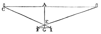
Fig. 2.
II. To gain the distance between two objects C and D (fig. 2) from any point A, taken in the line C D, erect the perpendicular A E: on which set off from A to E, 1 or 200 feet, more or less, according to the distance between the points C and D; set off from E to G in the prolongation A E, ⅛ or ⅒ of A E; at G raise the perpendicular G F, and produce it towards I; plant pickets at E and G, then move with another picket on G F till it becomes in a line with E and D; and on the prolongation of the perpendicular F G place another picket at I in the line with E and C; measure F I, and it will be as GE : AE :: FI : CD.
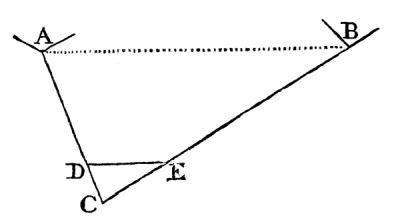
Fig. 3.
Landman’s Practical Geometry on the Ground.
III. To gain the inaccessible length A B, (fig. 3.) of the front of a fortification; plant a picket at C, from whence both points may be seen: find the lengths C A and C B by the method just given (Nᵒ 1.) make C E ¼, or any part of C B, and make C D bear the same proportion to C A: measure D E, then it will be as CD : DE :: CA : AB.
Note. Nearly after the same manner may be ascertained the distance from B to A when the point B is accessible; for having measured the line C B, and made the angle C E D equal to C B A, it will be, as CE : DE :: CB : BA.
IV. The distance of a battery, or other object, may be ascertained by the tangent scale on the breach of a gun. It is however necessary in this case to know the height of the object, the distance of which is required. Lay the gun by the upper line of metal for the top of the object, then raise the tangent scale till the top of the scale and the notch at the muzzle are in a line with the bottom of the object, and note what length of tangent scale is required: then say, as the length of the scale above the base ring of the gun is to the length from the base ring to the swell of the muzzle, so is the height of the object to its distance from the muzzle of the gun.
Lombard’s Tables.
V. The breadth of a river, or other short distance, may be taken thus:—take two pickets of different lengths, drive the shortest into the ground close to the edge of the bank; measure some paces back from it, and drive in the other till you find, by looking over the tops of both, that your sight cuts the opposite side.—Then pull up the first picket, measure the same distance from the second, in any direction the most horizontal, and drive it as deep in the ground as before.—Consequently, if you look over them again, and observe where the line of sight falls, you will have the distance required.
Teilk.
VI. The following simple method of ascertaining the breadth of a river may be sufficiently correct for some cases: Place yourself at the edge of one bank, and lower one corner of your hat till you find the edge of it cuts the other bank; then steady your head, by placing your hand under your chin, and turn gently round to some level spot of ground, and observe where your eyes and the edge of the hat again meet the ground; your distance from that point will be nearly the breadth of the river.
Teilk.
VII. Distances ascertained by the difference between the true and apparent level. See Levelling.
VIII. Distances measured by sound. See Sound.
IX. The following simple micrometer may be so usefully applied to military purposes, that I shall extract it verbatim from the Philosophical Transactions for 1791, where it is described by Cavallo. This micrometer consists of a thin and narrow slip of mother of pearl, finely divided, and placed in the focus of the eye glass of a telescope, just where the image is formed.—It is immaterial whether the telescope be a reflector, or a refractor, provided the eye glass be a convex lens and not a concave one, as in the Galilean construction.—The simplest way to fix it, is to stick it on the diaphragm, which generally stands within the tube, and in the focus of the eye glass.—When thus fixed, if you look through the eye glass, the divisions on the scale will appear very distinct, unless the diaphragm is not exactly in the focus; in which case the scale must be placed exactly in the focus, by pushing the diaphragm, backwards or forwards, when this is practicable; or else the scale may be easily removed from one surface of the diaphragm to the other, by the interposition of a circular bit of paper or card, or a piece of sealing wax.—This construction is fully sufficient when the telescope is always to be used by the same person; but when different persons are to use it, then the diaphragm, which supports the micrometer, must be so constructed as to be easily moved backwards or forwards, though that motion need not be greater than about the tenth or eighth of an inch. This is necessary, because the distance of the focus of the same lens appears different to the eyes of different persons; and therefore whoever is going to use the telescope for the mensuration of an angle, must first unscrew the tube which contains the eye glass and micrometer, from the rest of the telescope, and, looking through the eye glass, place the micrometer where the divisions of it may appear most distinct to his eye. The mother of pearl scale may be about the 24th part of an inch broad; its length is determined by the aperture of the diaphragm; its thickness that of writing paper. The divisions on it may be the 200th of an inch, which may reach from one edge of the scale to about the middle; and every fifth and tenth division may be a little longer, the tenths going quite across. When the telescope does not magnify above 30 times, the divisions need not be so minute. For the sake of those not conversant in trigonometry, the following is an easy method of determining the value of the divisions on the scale. Mark upon a wall or other place, the length of 6 inches; then place the telescope before it so that the 6 inches be at right angles to it, and exactly 57 feet 3½ inches distant from the object glass of the telescope. This done, look through the telescope, and observe how many divisions of the micrometer are equal to it, and that same number of divisions will be equal to half a degree, or 30´; and this is all that need be done to ascertain the value of the scale. The reason on which it is founded is, that an extension of six inches at the distance of 57 feet, 3½ inches, subtends an angle of 30´, as is easily calculated by trigonometry. To save the trouble of calculation, a scale may be made requiring only inspection. Thus, draw a line equal to the diameter of the field of the telescope, and divide its under side into the same number of parts as are on your micrometric scale, and, by the above operation on the wall, having determined the value of 30´, which we will suppose to correspond with 16 divisions on the scale, mark 30´ on the opposite side of the line, opposite 16 on the lower; 15 opposite 8, and so on.
By the following table the results may be ascertained by inspection only: thus, suppose an extension of 1 foot is found by the table to subtend an angle of 22′, the distance will be 156.2: and suppose at the distance of 171.8 an object subtends an angle of 20′, its height will be found to be 1 foot; or, suppose an object of 6 feet high to subtend an angle of 20′, the distance is 1030.8, by multiplying 171.8 by 6.
Table of Angles subtended by 1 Foot, at different Distances.
Minutes. Distances in feet. Minutes. Distances in feet.
1 3437.7 31 110.9
2 1718.9 32 107.4
3 1145.9 33 104.2
4 859.4 34 101.1
5 687.5 35 98.2
6 572.9 36 95.5
7 491.1 37 92.9
8 429.7 38 90.4
9 382.0 39 88.1
10 343.7 40 85.9
11 312.5 41 83.8
12 286.5 42 81.8
13 264.4 43 79.9
14 245.5 44 78.1
15 229.2 45 76.4
16 214.8 46 74.7
17 202.2 47 73.1
18 191.0 48 71.6
19 180.9 49 70.1
20 171.8 50 68.7
21 162.7 51 67.4
22 156.2 52 66.1
23 149.4 53 64.8
24 143.2 54 63.6
25 137.5 55 62.5
26 132.2 56 61.4
27 127.3 57 60.3
28 122.7 58 59.2
29 118.5 59 58.2
30 114.6 60 57.3
DRAG ROPES—
weight length
With 5 pins 6 lbs. 8 oz. 21 feet.

4 ” 5 6 13
3 ” 5 0 12
E mbarkation
1. Of Ordnance and Stores.—The first thing necessary is to prepare a list of all the articles to be embarked, with the weight of each. This list must have a large column for remarks. The tonnage required for bulky articles will be generally ⅓ more than their actual weight; but the tonnage of ordnance, shells, shot, &c. will be equal to their weight. If vessels be paid according to the tonnage they carry, the masters will of course stow away as much as the ships will hold; but if, by the voyage, they will be averse to loading their ships too much; a naval officer should therefore always attend to see that the ships are properly stowed.
Ordnance and stores may be embarked either for the purpose of merely transporting them to another situation, or for a military expedition. In the first case, each ship must be stowed with as much as it will carry, and every article that relates to one particular species of service or ordnance, must be put on board the same ship; that in case one ship be lost, the others may remain in themselves complete. This principle must of course be likewise attended to in an embarkation for an expedition; but a more particular distribution must take place of the stores when on board. With each piece of ordnance must be placed every thing necessary for its service; its side arms, carriage, limber, ammunition, &c. so as to be readily come at, when required to be disembarked. If it be an embarkation of ordnance, &c. for a siege, not only every thing necessary for the service of the pieces of ordnance should be arranged with them; but also every thing necessary for the construction of the battery on which they are mounted. It will be adviseable in this case, to put different natures of ordnance in the same ship, in proportions according to the service required of them. In general it will be best to put the heavy articles in first, and every thing that is light, easy to be removed, or likely to be first wanted, on the top. Previous to embarkation, the guns, carriages, waggons, &c. must be dismounted, but first numbered as follows: and the number of each article marked in the list, in the column of remarks. Give each piece of ordnance and its carriage the same number. Give the ammunition and other carriages, different numbers from the ordnance carriages. Then give every limber, whether of ordnance carriage, ammunition carriage, or waggon, the number of its respective carriage. If for a simple transport, arrange the small stores, side arms, &c. according to their several natures; but if for an expedition, every thing belonging to each particular piece of ordnance must be collected together, and the cases or chests in which they are put, marked with the number of the piece of ordnance to which they belong, their natures and description. If there be any doubt of the different parts of the carriages, being made with that uniformity, so essentially necessary, every part which is separated, must bear the number of its carriage. This precaution at any rate may be a good one, if the same vessel contain different natures of ordnance or carriages.
The axletrees need not be taken off the carriages, if the vessel be of a sufficient size to admit them when fixed, as they are not easily replaced without workmen and a tedious operation. When a carriage is dismounted, all the small articles, such as elevating screws, linch pins, drag washers, cap squares, &c. must be carefully collected, and secured in a box, marked with the description of stores, and number of the carriage to which they belong. All carriages or waggons embarked with their axletrees fixed, must be arranged in the ship, side by side, and alternately front and rear, that their axletrees may not interfere with each other, and take too much room. Every transport or other vessel employed in carrying troops or stores for an expedition, should be numbered on the quarters and on the bows, with figures as large as 2 or 3 feet, and on the sails, that they may be known at a distance. The number of the ship, her name and tonnage, and the master’s name must be entered in the list of the stores which she carries.
In disembarking ordnance and stores, they must be landed exactly in order, the reverse of what they were shipped. The carriages and waggons must be mounted as soon as possible, and every nature must be arranged as far from the shore as possible to prevent confusion. If the disembarkation take place in the presence of an enemy, the vessels of course must be loaded accordingly; and the field ordnance, with their carriages, ammunition, &c. must be so arranged as to be first landed, and with the greatest ease possible. In this case, the entrenching tools must also be kept in the greatest readiness.—Aide Memoire.
2. Of Troops.—All transports taken into His Majesty’s service, are under the direction of the Transport Board, and of their agents at the different ports at home and abroad. No troops or other persons can be put on board them, or victualled, but by an order from this Board, or one of its agents. Troops embarked on board transports or ships of war (except as marines) are only allowed ⅔ of a seaman’s allowance of provisions. (See the word Ration.) It is therefore necessary to divide the men into messes of 6 each. Six women to 100 men embarked on foreign service, are allowed provisions; and 10 women to 100 men on home service. The births on board transports, are usually made 6 feet square, and each admits 4 men at a time; but agreeable to the regulations for the army for 1799, one third of the men are always to be on deck; therefore 6 men (or one mess) are told off to each birth, ⅓ of whom are always on watch. The commanding officer of the troops on board a transport, has a right to peruse the charter party of the ship, which points out every different article, as firing, candles, boats, utensils, &c. which the ship is engaged to find for the use of the troops on board. It likewise expresses the part of the ship allotted to the officers, to the master, the mate, and the agent, should there be one on board.
EXERCISE of Artillery.—With 9 men to a field gun.
When 15 men are attached for the service of a gun in the field, they are numbered from 1 to 15; but when the gun is not to be advanced by men, the first six numbers are left out, and the remaining nine men are numbered from 7 to 15. The exercise of field guns of a heavy nature varies but little from the light ones. Though different duties done by the men attached to the one, should, as nearly as possible, be kept up at the other; as thereby is prevented that confusion which must arise when men removed from a light gun to a heavy one, change their numbers, though their duties at each be the same. The following will be the position of 9 men, for field ordnance of all natures, in the
1. Line of March.
Numbers 7, 9, 12, and 15, on the left of the gun; 8, 10, 13, 14, and 11, on the right; numbers 7 and 8 opposite the muzzle of the gun; 9 and 10 opposite the breech; 12 and 13 opposite the trail; 14 opposite the axletree of the limber; 11 opposite the shafts; 15 leads the limber horse; the driver leads the front.
2. Position and Duties of 9 men when prepared for Action.
Light Guns.—7 spunges, 8 loads, 9 serves the vent, 10 fires, 11 commands, 12 carries the match and water bucket, 13 serves 8 with ammunition from 14, who carries a cartouch and a pair of drag ropes; 15 holds the limber horse, and carries a cartouch.
Positions.—7 between the right wheel and the muzzle; 8 between the left wheel and the muzzle; 9 clear of the rear of the right wheel; 10 clear of the left wheel, both in a line with the vent; 11 on the left of the handspike; 12 on his right, clear of 9; 13 covers the left wheel, 5 yards in the rear; 14 covers the right wheel, 10 yards in the rear. The limber is 25 yards directly in the rear of the gun.
Heavy Guns.—This is the same as with the light guns, except that 7 and 8 stand outside the wheels, and 8 assists 7 to ram home, if necessary.
Howitzers.—Positions are the same as the heavy guns, but the duties different. 7 spunges, uncaps the fuze, and puts in the shell; 8 takes the sheepskin out of the piece, lays it on the ground, with the woolen side up, loads with cartridge, wipes the bottom of the shell, (when 7 holds it up) puts in the sheep skin again, and pulls it out with his left hand on the word Ready: He stops the muzzle with it immediately that the piece is fired; 9 serves the vent; 10 fires; 11 commands; 12 carries the match and bucket; 13 serves 8 with cartridges from a cartouch; 14 serves 7 with shells from the limber, which he lays on the sheep skin; 15 attends the limber. As from unavoidable accidents the number of men attached to a gun, may be reduced, it will be necessary if the vacancies happen amongst those doing the most essential duties, to immediately replace them by those doing the most subordinate duties.
The following method of distributing the duties amongst a smaller number of men, will be equally applicable to all natures of field ordnance.
Nᵒ. of men. Nature. Numbers retained. The vacancies, how supplied.
9 Gun 7 8 9 10 11 12 13 14 15 complete.
Howr 7 8 9 10 11 12 13 14 15
8 Gun 7 8 9 10 11 13 14 15 Nᵒ. 12 being dropt, Nᵒ. 11 does his duties.
Howr 7 8 9 10 11 13 14 15
7 Gun 7 8 9 10 11 13 15 Nᵒ. 14’s pouch is laid on the ground; 13 carries it when moving.
Howr 7 8 9 10 11 14 15 Nᵒ. 8 serves himself with cartridges
6 Gun 7 8 9 11 13 15 Nᵒ. 9 serves the vent with his left hand faces about and fires. Tube box on left side.
Howr 7 8 9 11 13 15
5 Gun 7 8 11 13 15 Nᵒ. 11 does all the duties of 9, as in the last change, his own duties, and those of 12.
Howr 7 8 11 14 15
4 Gun 7 8 11 15 Nᵒ. 8 fetches his own ammunition; 7 serves his own shells.
Howr 7 8 11 15
3 Gun 7 11 15 Nᵒ. 7 serves and loads all the ammunition. —Nᵒ. 7 & 15 must change duties occasionally.
Howr 7 11 15
3. To Limber up.—Light Guns and Howitzers.
The whole of the men face towards the gun; 11 unships his traversing handspike; the limber is brought up by 15, rather to the right of the gun, and then turned to the left about; 12 and 13 raise the trail, and place it on the limber, in which they are assisted by 7 and 8 bearing down on the muzzle, and 9 and 10 at the wheels; 11 chains the limber.
Heavy Field Guns, or Howitzers.—The only difference from the above is, that 9 and 10 assist 12 and 13 to raise the trail, and 14 and 15 stand to the gun wheels.
4. To unlimber.—Light Guns and Howitzers.
The whole face towards the gun; 11 unchains the limber; 12 and 13 lift the trail off the pin tail, and set it on the ground, in which they are assisted, as in limbering up, by 7, 8, 9, and 10; 11 ships the traversing handspike, and the whole assume the position for action. The limber is led by 15, and the driver, 25 yards to the rear, and there turned to the left about. The leading horse is unhooked by the driver, and tied to the rear of the limber.
Heavy Field Guns, and Howitzers.—The same as the light ones, except that 9 and 10 assist 12 and 13 to raise the trail, and 14 and 15 stand to the gun wheels. The heavy guns have generally mounted riders, in which case the leading horses are not unhooked.
It must be understood, that simply to limber up, or to unlimber, means that the gun is to be placed upon its limber, or lifted off, without changing its direction; but guns may be limbered up to the front, to the right, or to the left, according as it is intended to advance in any one of those directions; and unlimbered to the rear to prepare for action to the front, to the left for action to the right, and to the right for action to the left. To limber up, or to unlimber, in any of these situations, is exactly the same as those already given, except that in the first, previous to limbering up, the trail is thrown round by No. 11, assisted by 12, if necessary, into the direction specified by the word of command, and the limber is brought up to that side to meet it; and in the second, the trail, after being taken off the limber, is carried round to the rear, right, or left, according as the word of command expresses, before it is put to the ground, and the limber goes round to the rear of the gun.
It must be here remarked, that the front of a gun, or line of guns, or column of guns, is that to which the men at the gun front, without any respect to the situation of the gun or carriage. The trail of the carriage, when moved round to the rear or the contrary, whether in limbering up or unlimbering, must always be carried round to the right, and the limber, or a horse, when brought up to advance or retire a gun, must always be brought up on the right side, and go off on the left; and whenever the limber is turned about, it must be to the left about. By attending to these precautions the greatest confusion is avoided.
Other Methods of advancing Guns.
5. The gun being in the position for action, prepares to advance slow; 7 and 8 step outwards, 3 yards; 9 and 10 place themselves in line with the axletree, leaving room for 12 and 13, (who each bring a drag rope from 14) to pass between them and the wheels; 12 and 15 as they pass give the chain ends of the drag ropes to 9 and 10, who hook them to the washers; 12 and 13 man the Front pins, 7 and 8 the center, and 9 and 10 the rear.
This is only practised with light guns.
Prepare for Action.—7, 8, 9, and 10 quit their pins; 12 and 13 go to the rear; 9 and 10, as soon as 12 and 13 have passed them, unhook the drag ropes; 12 and 13 carry them to 14; 13 gets his ammunition.
6. Prepare to advance with a Horse.
Light Pieces.—7 gives his spunge to 9; 7 and 8 unhook the chain traces from the breast of the carriage, and lay them over the spokes of the wheels; the driver brings up a horse to the front, by the right; 7 and 8 unhook the horses traces from the back band, and hook them to the short gun traces, and then take post outside the wheels; 7 takes his spunge.
Heavy Pieces.—This is done with two horses, one before the other; 7 and 8 hook the horse, the driver rides to the rear horse, and 9 and 10 hook the rear horse to the short gun traces.
Prepare for Action.—The different numbers exactly undo what they have just done.
7. Prepare to advance with a Limber.
The only difference between this, and advancing with a horse, is that the limber is brought up to the front; and 15 brings up a drag rope, the center of which he lays over the pin tail, and 7 and 8 hook the ends to the short drag chains of the carriage.
Methods of retreating Guns.
8. Prepare to retreat slow.—7 and 8 place themselves in a line, with the axletree of the carriage on each side; 9 and 10 in a line with the trail; 12 and 13 get each a drag rope from 14, and give the chain ends to 7 and 8, who hook them to the drag washers; 7 and 8 man the rear pins: 9 and 10 the center-pins; 12 and 13 the front; 10 carries the linstock; 15 turns the limber. This is only done with light pieces.
Prepare for Action.—7 and 8 unhook; 9 and 10 quit their pins; 12 and 13 carry back the drag ropes to 14; 14 gets his ammunition; 15 turns the limber to the front; the whole resume their places in action.
9. Prepare to retreat with a Horse.
Light Pieces.—7, 8, 9, and 10 place themselves as in retreating slow; 13 gets a drag rope from 14, and gives it to 9 and 10, who lay the center of it across the top of the traversing handspike, and then under the trail hooks; 12 and 13 hook the traces of the horse brought up by the driver to the ends of the drag rope; 15 turns the limber.
Heavy Guns.—This is done in the same manner, but with two horses; 9 and 10 hook on the rear horse, and 12 and 13 the leader.
Prepare for Action.—The same numbers undo what they have just done.
10. Prepare to retreat with a Limber.
The limber is brought up to the trail of the carriage; 12 and 13 bring up each a drag rope, and hook the chain ends to the limber; while 9 and 10 hook the other ends to the trail hooks.
11. Prepare to fire retreating with a Horse.
This is done exactly as in the article Retreating with a Horse, except that two drag ropes are brought by 12 and 13, who hook the chain ends to the horses traces, while 9 and 10 hook the other ends to the trail hooks.
12. Prepare to fire retreating with a Limber.
The limber in this case is fixed exactly as in retreating with a limber; but at the distance of two drag ropes length: this therefore employs two pair of drag ropes. In firing and retreating, if the gun retreat loaded, 10 is not to light his port fire, nor 11 to point till ordered. Upon the word Halt, Nᵒ 7 must ram home the cartridge, and the whole face about. In preparing for action from any of these positions, the same numbers undo exactly what they have just done, and immediately fall into their places for action; and the duties are the same with the heavy field pieces as with the light ones.
Exercise of a Field Gun with 15 Men.
When a light gun has 6 drag rope men attached to it, the duties of the standing numbers, that is, the numbers from 7 to 15 continue the same in all the exercises just mentioned; but they assist also in the movements of the gun by drag ropes.
In the line of march, 1, 2, and 3, are on the left of the gun in the rear of 7; and 4, 5, and 6 on the right, in the rear of 8.
In the position for action, 1, 2, and 3, hold the right drag rope, and 4, 5, and 6 the left, and dress in a line with the axletree. On the word Load, 3 and 4 unhook the drag ropes from the drag washers, 3 holds the hook in his left hand, and 4 in his right; and they hook on again at the word Cease firing.
On the word Prepare to advance quick, 2, 3, 4, and 5, slip under the drag ropes; 2 and 5 man the loop ends on the inside; 3. and 4 the first pins on the inside; 7 and 8 move to the second pins on the inside; 1 and 6 remain at their pins: 9 and 10 move to the second pins on the outside; and 12 and 13 to the rear pins on the outside; 14 assists 11 at the traversing handspike; 13 lifts up the trail for 11 to put in the truck; and 12 gives his match to 10.—Then the word,
Prepare for Action.
2, 3, 4, and 5, slip back again under the drag ropes, and the whole resume their places for action.
Word—With two pair of Drag Ropes, prepare to retreat quick.
3 and 4 unhook from the drag washers, and march to the rear; 2 and 5 follow, and 1 and 6 hook the loop ends of the drag ropes to the trail hooks. 12 sticks his linstock in the ground, and with 13 brings the spare drag ropes from 14, and gives the chain ends to 7 and 8 to hook to the drag washers; 7, 9, and 12, man the right drag rope, and 8, 10, and 13, the left. To resume the position for action, on the
Word—Prepare for Action.
7 and 8 unhook the spare drag ropes, and 12 and 13 carry them back to 14; 1 and 6 unhook from the trail, and 3 and 4 hook the other ends to the drag washers.
Word—Prepare for Action retreating.
The drag rope men change as in retreating. Upon the word Load, 1 and 6 unhook from the trail, and hook on again at the word Cease firing.
It must be here remarked, that in the exercise with 15 men, only the additional duties have been detailed; the duties of the standing numbers in action, advancing or retreating, being still the same as without drag rope men. In limbering and unlimbering, the drag rope men have no duties, but are ready to assist with the drag ropes. The truck is always put on in all movements with the drag ropes, and thrown off at the word Load.
Exercise with Heavy Ordnance in a Battery.
32, or 42 Pounder.
10 Men. 9 Men.
1 spunges; 2 loads. 1 spunges, 2 loads.
3 and 5 run the gun up. 3 and 5 run up.
4 and 6 run up and elevate. 4 runs up and elevates.
7 serves the vent, traverses, primes and runs up. 6 brings cartridges, runs up, and elevates.
8 runs up, traverses, and fires. 7 serves the vent, runs up, traverses, and primes.
9 brings cartridges. 8 runs up, traverses, and fires.
10 points and commands. 9 points and commands.
8 Men. 7 Men.
1 spunges; 2 loads and runs up. 1 spunges and runs up.
3 runs up. 2 loads and runs up.
4 and 5 run up and elevate. 3 runs up and elevates.
6 brings cartridges, runs up, and traverses. 4 brings cartridges, runs up and elevates.
7 serves the vent, runs up, traverses, and primes. 5 serves the vent, runs up, traverses, and primes.
8 points, fires, and commands. 6 runs up, traverses, and fires.
6 Men.
1 spunges and runs up,
2 loads, runs up, and elevates.
3 runs up and elevates.
4 brings cartridges, runs up and traverses.
5 serves the vent, runs up, traverses and primes.
6 runs up, points, fires, and commands.
24 Pounder, &c.
8 Men. 7 Men.
1 spunges, 2 loads. 1 spunges, 2 loads.
3 and 4 run up and elevate. 3 runs up and elevates.
5 serves the vent, runs up, traverses, and primes. 4 brings cartridges, runs up, and elevates.
6 runs up, traverses, and fires. 5 serves vent, traverses, and primes.
7 brings cartridges. 6 runs up, traverses, and fires.
8 points and commands. 7 points and commands.
6 Men. 5 Men.
1 spunges, runs up, elevates. 1 spunges, runs up, elevates.
2 loads, runs up, and elevates. 2 brings cartridges, loads, runs up, and elevates.
3 serves the vent, runs up, traverses, and primes. 3 serves vent, runs up, traverses, and primes.
4 runs up, traverses, fires. 4 runs up, traverses, fires.
5 brings cartridges. 5 points and commands.
6 points and commands.
4 Men. 3 Men.
1 spunges, runs up, points. 1 spunges, runs up, points, and fires.
2 brings cartridges, loads, runs up and elevates. 2 brings cartridges, loads, runs up, elevates, traverses.
3 serves vent, runs up, traverses, elevates, and primes. 3 serves vent, runs up, elevates, traverses, and primes.
4 runs up, traverses, fires.
4⅖, or 5½ Inch Mortar.
2 Men. 3 Men.
1 spunges, runs up, brings shells, puts them in, traverses, and primes. 1 spunges, runs up, traverses, brings shells, and puts them in.
2 serves the vent, runs up, brings cartridges, puts them in, points, and fires. 2 brings cartridges, puts in, serves the vent, runs up, primes, and fires.
3 points, elevates, and commands.
8 Inch Mortar, or Howitzer.
5 Men. 4 Men.
1 spunges, runs up, dredges. 1 spunges, runs up, dredges.
2 runs up, brings cartridges and puts them in. 2 runs up, brings cartridges, and puts them in.
3 runs up, brings shells, puts them in, traverses, primes. 3 serves the vent, brings shells, and puts them in, runs up, traverses, and fires.
4 runs up, traverses, fires. 4 runs up, points, commands.
5 serves vent, points, and commands.
10, or 13 Inch Mortar.
10 Men. 6 Men.
1 spunges, runs up, puts in shells, and dredges. 1 spunges, runs up, puts in shells, dredges, and traverses.
2 runs up, brings cartridges, puts them in, and puts in the shells. 2 runs up, brings cartridges, and puts them in, puts in shells, and traverses.
3 brings cartridges. 3 and 4 run up, bring, shells, and traverse.
4 and 5 bring shells. 5 runs up, serves vent, and primes.
6, 7, 8, and 9, run up, and traverse. 6 runs up, points, fires, and commands.
8 serves vent and primes.
9 fires, 10 points, and commands.
Exercise of the Gin.
The complement of men for a gin is usually 1 noncommissioned officer and 10 men; they are numbered from 1 to 10, the noncommissioned officer being 11.
To carry a Gin.
1 and 2 carry the prypole, 3 and 5 the right cheek, 4 and 6 the left, 7 the windlass and fids, 8 and 9 the blocks and tackles, 10 the handspikes, &c.
To Set up a Gin.
1 and 2 put a common handspike through the ring, near the foot of the prypole, at which they lift; 3 and 4 steady the cheeks, by placing each a handspike against the lower cross bar; 5, 7, and 9 lift the right cheek; 6, 8, and 10 the left cheek; 11 gives directions. The tackles must be hooked on before the gin is raised.
To work a Gin.
1 and 3 man the right handspikes of the gin; 2 and 4 the left; 5, 6, 7, and 8 hold on the fall, and pull in the slack; 9 and 10 steady the gun, 9 at the muzzle, 10 at the breach. The tackle hook must be fixed directly over the dolphins, if any, or a little behind the trunnions.
In heaving, when the ends of 1 and 4 handspikes come as low as their knees, 2 and 3 put theirs into the upper holes of the windlass, and 3 gives the word Fetch, upon which 1 and 4 clear their handspikes from the windlass, and 1 gives the word Heave; 2 and 3 then bear down their handspikes, and remain fast till 1 and 4 having taken their fresh purchase, 1 gives the word Fetch, when 2 and 3 clear their handspikes, and 3 gives the word Heave; and so on alternately, till the gun is at its proper height, when the handspikes in the upper holes are made to rest against the upper cross bar, and 5 makes fast the fall to the lower cross bar; and if required to lower the gun, eases the fall off from the windlass; 5, 6, 7, and 8 move the carriage, as required, under the gun.
Exercise of the Sling Cart.
The men for the service of the sling cart are numbered from 1 to 7; the noncommissioned officer being No. 7; No. 1 and 2 sling the gun. The gun must be laid with 1 trunnion touching the ground, and the sling passes diagonally round the gun; being before one trunnion, and behind the other; and that end of the sling which goes round the lower side of the gun must be the end to be acted on by the windlass; as by that means the trunnions become horizontal when the gun is raised; No. 1, 3, and 5 man the right lever; 2, 4, and 6 the left lever; and upon the word from the noncommissioned officer they heave together: the noncommissioned officer then directs left hand lever hold on, right lever fetch; the right lever takes a fresh purchase: then, right lever hold on, left lever fetch; the left lever takes a fresh purchase; they then heave together again. When the gun is high enough, 7 puts in the pall; 1 and 2 take out the levers, and put in the prypole; 3 and 4 raise the breech of the gun with two common handspikes, and 5 and 6 lash it to the prypole: 1 and 2 then lay their levers along side the prypole, and 3 and 4 their handspikes on the top of them, which 5 and 6 lash all fast together.
F ascines—have different names, according to their size and use.
1. Saucissons are usually made 18 feet long, and from 10 to 12 inches in diameter; and are used for the revetement of embrazures, or for the corners of the parapet.
2. Battery Fascines—are made from 8 to 12 feet long, and from 10 to 12 inches thick; used for the revetement of the parapet, &c.
3. Trench Fascines—from 4 to 6 feet long, and from 4 to 9 inches thick; used at sieges.
4. Water Fascines—6 feet long, from 1 to 2 feet thick; used to cover marshy and wet situations; they must be loaded with stone to make them sink.
5. Covering Fascines—are used to form the tops of magazines or saps. They ought therefore to be composed of the strongest branches, with the addition of a few poles, that they may bear a considerable weight.
6. Sap Faggots—3 feet long, 8 inches thick.
Attentions in making Fascines—The bands must be from 10 to 12 inches asunder, of birch, hazle, or other pliant wood, well twisted. The fascines must be drawn close with a choke rope, previous to being tied.
In laying the wood to form the fascines, the shortest and smallest pieces should be laid inside. Three men are usually employed at each trestle, with two to collect the stuff.
In general a saucisson of 18 feet may be finished at each trestle in half an hour.
Birch and fir are the bell woods for this work.
Fascines are sometimes bent so as to coincide with the angles of the battery. The Prussians double some of the fascine stuff, so as to make a loop at the end of the fascine, which being laid over one another at the corners, and a stake driven through the loops, are very strong.
FIRE SHIP. —Proportion of combustible Stores for a Fire Ship of 150 Tons.
Nᵒ.
Fire barrels, filled with composition 8
Iron chambers, to blow open the ports 12
Composition for priming, barrels 3½
Quick, match, ” 1
Curtains, dipped 48
Reeds, long, single dipped 150
” short, double dipped 75

single dipped 75
Bavins, single dipped 250
The fire barrels are about 2 feet 4 inches high, and 1 foot 6 inches diameter. Each barrel must have four holes of about 6 inches square cut in its sides; and these holes must have a square piece of canvass nailed over them quite close. They are then filled with the same composition as for carcasses, and 4 plugs of about 1 inch diameter and 3 inches long, and well greased, are thrust into the top, and then left to dry. When dry, these plugs are taken out, and the holes driven with fuze composition, and quick match at the top; which goes from one hole to the other: after this the top is smeared over with mealed powder mixt up with spirits of wine. When dry again, a sheet or two of brown paper is laid over the top, and then one of the canvass covers, which is made secure by the upper hoop of the barrel.
Composition for dipping Reeds, Bavins, and Curtains.
lbs.
Rosin 120
Coarse sulphur 90
Swedish pitch 60
Tallow 6
Mealed powder 12
This proportion will dip about 100 reeds and 25 bavins.
Each curtain contains 1 square yard of barras.
Each cover for fire barrels 1 do. of sacking.
Immediately that the curtains, covers, &c. are dipped, they are to be strewed over with fine brimstone, before the composition grows cold.
The iron chambers, for blowing open the ports, hold from 9 to 11 ounces of powder. They are fixed in such a manner as to prevent their recoil, and to ensure the ports being blown open. The vents are generally corked up, and covered with a piece of barras, till required to be primed.
To fit out a Fire Ship.—The whole breadth of the fire room is to be divided into 9 parts, and troughs laid the whole length of the room. Cross troughs, of communication are laid between them, about 20 in each row, perpendicular to the long troughs. These troughs are usually 4 inches wide, and 4 deep. There are two fire trunks and two fire scuttles on each side, under which the eight fire barrels are to be placed.
The reeds and bavins are to be tied down in the troughs. The curtains are to be nailed up to the beams, equally through the fire room. The ship is not to be primed when fitted out, but only when intended to be fired.
To Prime.
Composition for Priming.
Saltpetre pulverized 22 lbs. 8 oz.
Rosin 2 11
Sulphur 18 —
Mealed powder 45 —
Linseed oil 1 pint.
All the reeds and bavins are to be taken up, and a little of the above composition sprinkled in the bottom of the troughs; the reeds, &c. to be then gently tied down again. Quick match of 6 or 8 threads doubled must be laid along on the tops of all the reeds &c. and the priming composition strewed over it, and over all the fire room. The covers of all the fire barrels must be cut open, and made to hang down on the sides of the barrels. Leaders of strong quick match must be laid from the reeds to the barrels and to the chambers; and must be tied down to the vents to insure its not falling off. Strong leaders of quick match; 4 or 5 times doubled, must be laid from the reeds to the sally ports; and the sally ports must be connected by quick match, that the whole may take fire at once.
The following method is now adopted of producing an external fire, in addition to the internal fire, before gained by the fire room.
Fire boxes filled with the carcass composition, are distributed in the following manner, in a ship of three masts:
1 Suspended from each of the catheads and davits, 4
on each side the bow
8 Slung across the bowsprit 8
4 Across each of the outriggers abaft 8
2 From the graplins of each of the 12
lower yardarms
1 From the deadeyes on each side of the 6
three round tops
1 From the middle of the inside of the main, fore, 6
and mizen shrouds
44
The boxes are suspended by chains and hooks, and those slung across the bowsprit and outriggers, are fixed by staples. The two inner ones are laid with leaders of quick match, which fire instantly, or with portfires, which burn a given time; they communicate with the outer ones by reeds, which are tied down on the bowsprit and outriggers. The boxes hanging from the deadeyes and shrouds, are fired by curtains suspended from the shrouds, the lower one of which hangs immediately over one of the large fire barrels. The two boxes on each yardarm are hung one over the other; the upper one having a leader of quick match carried along the yard from the shrouds; and in burning will no doubt fire the lower one. Besides the boxes, there are fire barrels arranged as follows; 2 half barrels on the forecastle; 2 abaft the main deck, and 4 on the main deck; 2 in each roundtop, placed against the masts; and 4 large fire barrels under fire trunks, to convey fire to the curtains on the shrouds. All these fire barrels and boxes are to be fired by separate leaders of quick match or portfire, in order that any part of the ship may be fired to cover its approach by the smoke; and the remaining part instantaneously upon quitting the ship. It has been found by experiment, that two men with lighted portfires can set fire to the whole of the leaders on the deck, bowsprit, catheads, outriggers, &c. in less than a minute; therefore the risk of trusting to one main leader to the whole, may be avoided.
The leaders are laid in painted canvass hose made for the purpose.
FLINTS—are usually packed in half barrels.
Weight.
Qrs. lbs.
One half barrel contains Musquet, 2000 2 14
Carbine, 3000 2 10
Pistol, 4000 2 15
The most transparent and free from veins are esteemed the best flints.
cwts. qrs.
28 kegs of musquet flints take 18 0 in tonnage
10 kegs of pistol ” ” 3 2 ”
FORTIFICATION.—Practical Maxims in building Field Works.
1st. The spot on which works are to be constructed should determine their figure; nor should any attention be paid to preserve a regular form which does not occupy the ground to advantage.
2d. Every line must be so disposed, that the slope of hills all around even to the very bottom, be open to the small arms of the garrison; and every part should be discoverable to the distance of at least 500 paces.
3d. Works thrown up for the defence of a defile, should always be within musquet shot of it, which must not be more than 200 yards.
4th. The best defence in works that are flanked, or where one side is defended by the fire of another, is that formed by right angles.
5th. A salient angle should never be less than 60, and a re-entering angle than 90 degrees; nor greater than 120 degrees.
6th. The entrance to the work should always be made in the part least exposed to attack, and if possible in a re-entering angle.
7th Endeavor to present, if possible, a larger front to the enemy than he can occupy in making the attack.
8th. Avoid all ground commanded by an eminence, either in front, flank, or rear.
9th. Never leave the rear of a work so exposed that the enemy may turn it.
10th. Always make the angles of a work in the directions least exposed to attacks, and consequently always present a front to the most exposed.
11th. The garrison should never be drawn up more than two deep; and an ordinary pace of two feet is usually allowed for each file, and from 6 to 8 paces from each piece of ordnance.
12th. If a work is so large as to be defended by a battalion or two, a reserve should be allowed of about one sixth of the number.
13th. The space within a work should always be sufficient for the men to move and lie down. Every soldier will require at least 18 square feet, and every field gun at least 216 square feet.
14th. Provided the line is not made too extensive, the more inward space there is the better.
15th. A parapet to resist cannon shot should never be less than 12 feet thick; and for musquet shot not less than 6 feet.
16th. The height of the parapet must be regulated by the situation of the work, and of the adjoining ground; with this consideration, that its height above the banquette does not exceed 4½ feet.
17th. The depth and breadth of the ditch must be regulated by the quantity of earth required, for the parapet and banquette.
18th. A tete de pont, or work to cover the embarkation of troops, or the passage of a river, should, if possible, be made where the line of the river or coast forms a kind of re-entering angle; that the flanks of the corps, as well as those of the works, may be covered.
To carry on the Work.—The number of workmen must be proportioned to the time allotted for carrying on the work, the quantity of labour, and the number of hands capable of being employed at the same time. When the ditches are broad, the workmen may be posted in two rows; but if narrow, only in one. In the first case, the earth will be thrown by those who are on the outward edge of the ditch to the second row, and by them upon the parapet; for which reason the second row, to keep pace with the first, ought to be twice as numerous. The workmen should never be placed nearer than 2 paces, or 4 feet, from each other; and two men with shovels should be preceded by one with a pickaxe. If more than usual expedition be required, one man with a wheel barrow, or basket, may be added to six or eight with shovels. Another row of workmen should also be placed upon the parapet, to spread the earth and beat it down, as it is thrown up.
In fixing the fascines, three men will be sufficient for every 24 feet of the work, who should be provided with two mallets, a saw, and a handbill, or hatchet.
In order to form some idea of the time in which a field work may be completed, compute the number of cubic feet of earth to be excavated, thus; multiply half the sum of the breadth of the ditch at top and at bottom, by the depth, for the number of square feet in the profile; and this multiplied by the distance between the workmen in feet, will give the number of cubic feet each man has to dig: or being multiplied by the length of the ditch, gives the cubic contents of the ditch. Now, one man is supposed to be able to move 216 cubic feet of earth in a day, during the summer; but this is not always the case. If a field work be completed in 24 hours, it will be as much as the most diligent workmen are capable of. This time is generally allowed for the formation of a weak profile; 48 hours for that of a stronger, with a revetement of fascines; and 72 for the strongest.
The different slopes for the works must depend upon the nature of the soil, and the materials of which the work is composed. The interior slope of the parapet, though it be fascined, should be ⅙ of its height; exterior about ⅔ its height. The slope of the banquette equal to its height. The slope of the scarpe or counterscarpe of the ditch, should be from half its height to its full height, according to the soil. The superior slope of the parapet must entirely depend upon the situation of the work, and that of the surrounding country. The interior slope of the parapet is generally lined with fascines, to keep up the earth; but it is not absolutely necessary to fascine the exterior slope, if the soil be pretty stiff. The embrazures are generally made 20 inches wide on the inside, and 9 feet on the outside; they must always be lined with something to retain the earth; turf is generally preferred, as fascines are so apt to take fire.
The manner of making the materials for field works, may be seen under the heads Fascines, Gabions, Hurdles, &c. and the manner of estimating the quantity of materials for works of this kind, may be seen under the word Battery.
Fortification—Permanent.
A parapet, to resist cannon, should never be less than 18 feet thick in earth, and 8 or 9 in masonry. A wall need only be two feet thick in masonry, to resist musquetry. The parapet should always be 4½ feet above the banquette, and 7½ or 8 feet above the rampart, or terre plein.
The Rampart should always be sufficiently wide to allow for the platform, and for two carriages passing each other; about 9 fathoms at top. A parapet of earth, though it takes more room, is always preferable to one of masonry, when it can be raised; though the only objection to the masonry is the number of splinters it produces.
Entire Revetements of masonry are not advantageous for the same reason. The masonry of revetements should not be so high as to be seen or battered from a distance: earth parapets are battered in vain, as the earth forms a natural slope.
The best Escarpe is made of masonry, either in wet or dry ditches, be the earthen one ever so well fraized or palissaded. The earthen one may be stormed without making a breach. The escarpe should be 30 or 35 feet high.
The Counterscarpe should also be of masonry, and not less than 12 feet high. The inconveniences of an earth or low counterscarpe, are the impossibility of defending to the last the covert way; as the enemy may descend into the ditch, and again mount the covert way, and so get in the rear of the traverses. The enemy may find his way along the natural slope of an earth counterscarpe, and is not delayed by a tedious operation of getting into the ditch. Besides, the natural slope of the end of an earth traverse prevents its effectually covering the covert way.
Ditches are generally 15 or 18 toises wide. Dry ditches are always preferable to wet ones, on account of the shelter they afford the troops, and the ready communication with the outworks, without the constant trouble and danger of bridges.
The Covert way should be 5 toises wide; less would crowd the troops, and more would allow room for the enemy to erect batteries in it.
The whole of the glacis should be seen, not only from the crest of the parapet, but from the embrazures in the parapet.
The Tenaile, must not be so high as to prevent the flank guns in one bastion seeing the breach that may be made in the collateral one.
Ravelins are best without flanks; their faces directed to 10 toises from the shoulders of the bastions.
The crest of the parapet of the body of the place should be 8 feet above the crest of the glacis, to command it across a ditch of 15 or 20 toises.
The crest of the parapet of the ravelin is 3 feet lower than that of the body of the place, in order that it may be more effectually commanded from the place; and therefore to enable the parapet of the ravelin to command its own glacis, the ditch is only made 10 toises, and this glacis is a foot lower than that of the body of the place.
There must be an equilibrium of defence established through every front of a fortified place; for it will be needless to strengthen any particular front, if the others from their weakness be left exposed. The following remarks may enable an observer to appreciate the value of particular works, in the proper application and arrangement of which that equilibrium consists.
Intrenchments within the works add much to their defence. In large bastions with obtuse flanked angles, the best intrenchment is formed of the front of a fortification, or of two demi bastions and a curtain, connecting the angles formed by the flank and curtain. If this intrenchment be advanced to the shoulders of the bastion, so as to include its flanks, as is often the case, it will be subject to be taken in the rear, by the fire from the counter batteries opposed to the flanks. But in bastions with acute flanked angles, which do not afford sufficient space for this kind of intrenchment, Cormontaigne proposes one in the form of a cavalier, whose faces and flanks are parallel to those of the bastion. The first kind of intrenchment does not operate in the defence of the place, till after the passage of the ditch; till which time it remains entire, and then capable of a very great defence. The second kind becomes a support to the bastion from the first commencement of the siege; but it is therefore subject to have its defences destroyed at a distance. Nor is its defence equal to that of the other form.
Counterguards should possess the three following properties: 1st. They must cover effectually the principal work before which they are placed; at least that part of it, which can be battered in breach. 2d. They must be lower than the work which they cover; but not so low as to permit its revetement to be seen. 3d. They must be so narrow as not to afford room for the besiegers to erect batteries in them, against the work which they cover, and therefore not leave the besiegers a choice of positions. The counterguards in Coehorn’s system are only of earth, through which it is necessary to make an opening, before the capital work can be battered.
Horn or Crown Works, unless to occupy some important point, to strengthen some weak side, or to afford more room for a confined garrison, are rather a weak than a strong arm to a place. This is particularly the case when they are constructed with smaller, and consequently weaker fronts, than that part of the body of the place which they cover; as they facilitate, when taken, the approaches to the body of the place. This is remedied by constructing their fronts of the same strength as the front or fronts which they cover. They also facilitate the taking of the place, by exposing the revetement of the work on which their branches are directed, to be battered in breach, along the ditches of those branches. This is a great evil, even to an outwork, but is of serious consequence if they rest upon the body of the place. This defect has been remedied by placing these works altogether outside of the covert way, and allowing their ditch no communication with those in the rear. In this case their gorge must be made very secure to prevent its being turned.
An Advanced Covert way, is esteemed amongst the best means of adding to the defence of places. Besides the advantages common to the usual covert way, it has many peculiar to itself. It however seems necessary to ensure to it the many advantages of which it is susceptible, (beside being properly palissaded,) that it should be secured in the rear by a wet ditch, as the only means of giving it an inaccessible counterscarpe, and at the same time keeping it under the fire of the musquetry of the place. This kind of covert way is generally supported by redoubts upon the capitals of the bastions and ravelins; which from their position cannot mask the fire of the place; and being mounted with artillery, oblige the besiegers to commence their attack at a great distance, and very much to extend their operations; and as their establishment upon this covert way must effectually mask the fire of their first batteries, it must greatly increase their labour. The retreat from these redoubts must be secured by an underground passage.
Countermines are undoubtedly one of the first means of strengthening places. For this article we refer to the word Mines.
Detached Redoubts, when circumstances of situation favour them, are employed with great success. They are usually detached and totally unconnected with any of the works of the place, by any covert way or other aboveground work; and have for objects, either the opposing an additional obstacle to the besiegers at the point they occupy, or the rendering the adjoining fronts inaccessible, by an enfilade or reverse fire upon the approaches. They also afford at their gorge, a most excellent rendezvous and retreat for sorties; upon the level of the country, and without the difficulty of filing troops through the barrier of a covert way.
But in order to insure to the detached work or works, all these advantages, it is necessary that they should be either totally inaccessible to the besiegers, by reason of the natural difficulties of their situation, as in an inundation, morass, &c. or be made secure by art, from being taken by storm, and only attackable by regular approaches. They should be under cover of the fire of the place; but if their distance be too great for that, an intermediate work must be established to give them support. Their best form is that of a bastion with retired flanks; and a strong system of countermines the most effectual way of prolonging their resistance.
General Remarks.—The larger the flanked angles of works, the more direct will be their fire, and that of their covert way, upon the approaches; the greater extent will they oblige the besiegers to occupy in their parallels and batteries; and the more will they oblige the besiegers to expose themselves to the fire of the fronts collateral to the one attacked. Faces of works directed to inaccessible situations, such as rivers, lakes, &c. from whence they cannot be enfiladed by ricochet batteries, add greatly to the strength of a front.
If the flanked angle of a ravelin be so advanced as to see in reverse any battery erected upon the crest of the glacis, or in the covert way of the bastions, it will increase the strength of that front; because it will oblige the besiegers to gain possession of the ravelin, before they can make any lodgement, from which they can batter the bastions. This is the case in Cormontaigne’s system: and a place thus fortified, obliges the besiegers to attack and gain two ravelins, to get at the bastion between them. Beside, if this system be applied to a right line, or to a polygon of many sides, the prolongations of the faces of the bastions, will be intercepted by the flanked angle of the ravelins, and consequently make the establishment of enfilading batteries against them very difficult. A work which admits of a breach being made in it (particularly the body of the place) at a distance, very much facilitates its being taken. The ditch of the ravelin affords an opening through which the besiegers may make a breach in the face of the bastion, from the glacis, opposite the flanked angle of the ravelin, and is therefore subject to this defect. A counterguard before the bastion, lessens this evil, by transferring the breach from the body of the place to the ravelin; but it requires a counterguard also before the ravelin, effectually to cure it. A crown or horn work also produces this evil; its remedy was given, in speaking of those works.
The direction of the flanks or faces of a work is not so material as relating to the fire of artillery, as to that of musquetry; for artillery is never fired without being pointed, but musquetry is fired mechanically, and perpendicular to the parapet, without much attention to the object to be struck.
A work in the neighbourhood of a height must be defiladed[7] from that height, that is, instead of being built upon a horizontal plane, it must be erected upon an imaginary inclined plane, passing from somewhere in the interior of that work, over the most commanding points of the height: and every part of the works must bear the same relation to this inclined plane, that they would do, to a horizontal plane in a level country.
A work is not therefore always to be condemned, because it is in the neighbourhood of a height; for if it be properly defiladed from that height, it will receive a great advantage over the approaches of the besiegers, carried on down an inclined plane towards it. But a work to be properly constructed in the neighbourhood of heights, must not uniformly preserve the same distance from those heights, unless their summits be all upon the same level; but must approach them at their lowest parts, and recede from them as they rise; thus will the necessary plane of defilement preserve nearly the same degree of obliquity throughout.
The Dimensions in the following Table of Vauban, are thus applied:
The Fort is mostly for squares.
The Little for citadels, commonly pentagons.
The Mean for all fortifications from the hexagon and upwards.
The Great is seldom used but in irregular fortifications, and particularly on rivers.
Principal Dimensions of Fortifications, according to Vauban.
Side of Polygon Length of Perpendicular Faces of Bastions Capital of Ravelins
Forts. 80 10 22 25
90 12 25 28
100 12½ 28 30
110 14 30 35
120 15 33 38
130 16 35 40
Little Fortification. 140 20 40 45
150 21 42 50
160 23 45 50
170 25 47 52
Mean 180 30 50 55
190 31 53 55
Great. 200 25 55 60
260 22 60 50
Dimensions of Walls and their Counterforts, from 10 to 50 Feet high, having a Slope of ⅕ their Height.
Wall. Counterforts.
Height. Thickness at Top. Thickness at Bottom. Distance between them. Breadth. Length.
Feet. Feet. Inch. Feet. Inch. Feet. Feet. Inch. Feet. Inch.
10 4 0 6 0 8 2 8 4 —
15 4 3 7 3 10 3 4 5 —
20 4 6 8 6 12 4 0 6 —
25 4 9 9 9 14 4 8 7 —
30 5 0 11 0 16 5 4 8 —
35 5 3 12 3 18 6 0 9 —
40 5 6 13 6 20 6 8 10 —
45 5 9 14 9 22 7 14 11 —
50 6 0 16 0 24 8 0 12 —
The heights in the above table are taken only from the bottom of the ditch, and do not include the foundations.
When the rampart is partly walled and partly turfed; then ⅕ of the height of the turfed part must be added to the breadth of the wall at the top given in the table.
The bases of all inward slopes of earth should be equal to their height, if not more.
The bases of all outward slopes of earth ⅔ of their height.
The superior slopes of all parapets ⅙ of their breadth.
The slope of all walls, or revetement ⅕ of their height.
Though the above principles given for the erection of field works may assist an officer’s recollection who may be employed on that duty, the memorandums given respecting permanent fortification pretend to no such object: but may serve to remind an officer, if he should visit a fortification, of its essential requisites; and may assist his observations in passing round the works.
FUZES.—Composition.
Saltpetre 3 lbs. 4 oz.
Sulphur 1 —
Mealed powder 2 12
Nature. Fuze Diameter. Composition. Drove by one man in 1 day.
below the cup. at the bottom. at the cup. Diameter. Length. Time it burns.
Inches. Inch Inches. Inches. Inch. Inches. ″ Nᵒ.
13 2.1 1.575 2.49 .5 8.4 35 25
10 1.8 1.35 2.13 .438 7.2 33 25
8 1.3 1.25 1.78 .375 6.37 29 30
5½ 1.1 .825 1.3 .275 4.4 18 50
4⅖ 1.0 .75 1.18 .25 3.5 15 700
Grenades 0.8 .6 .9 .2 2.25 1000
Diameter inside the cup is 3 diameters of the bore.
Depth of the cup 1½ do.
Thickness of wood at bottom of the bore, 2 diameters.
To find the Length of Fuzes for any Range.
The 13 and 10 inch fuzes of the same length burn so nearly equal, that one common length answers both, as do the 8 inch, 5½ and 4⅖. Therefore, to find the length of fuze for any range, multiply the time of flight by .22 for the 13 and 10 inch, and by .24 for the 8, 5½, and 4⅖; which is the decimal part of an inch a fuze burns in a second. Fuzes are thought to keep better by being painted; and for field service, are often marked off by black lines into seconds and ½ seconds.
G abions—Small gabions of 3 feet high, and 2 feet diameter, are made with least trouble, and are easiest carried. The pickets for them must be 1½ or 2 inches thick, and 4 feet long. Large gabions are 6 feet high, and 3 feet in diameter; and require two men to carry them. The smallest gabions or baskets are formed of pickets, 1 inch in thickness, and 1 foot long: they are 12 inches in diameter at top, and 10 at bottom. The small gabions have 7 or 8 pickets, the large ones 9 or 10.
To make them.—The pickets are first to be fixed in the ground in a circle, the size of the bottom of the intended gabion; then a few twigs are to be wove through the upper ends, to keep them from flying out; afterwards the work must be begun at the bottom and continued upwards; and the whole being well driven down with a mallet, the edges must be secured by twigs, wattled up and down. The twigs of willow, birch, hazle, alder, poplar, and beech are proper for this purpose. The top of the gabion must be made very even, because that becomes the bottom when finished. Four men are usually employed on each gabion, with a billhook, a mallet, a spade, and two axes. Two collect the wood, while the other two form the gabion. A 3 foot gabion ought to be made in half an hour.
GIN Triangle.—Length of arms of the gin 16 feet 4½ inches. Roller, 6 feet long. Tackle fall, 78 feet of 3 inch white rope. Sling, 6 inch white rope.
For the different exercises of the gin, see the word Exercise.
GRAVITY.—Table of the Specific Gravity of several Solid and Fluid Bodies.
Platina 23400 Nitre 1900
Fine gold 19640 Ivory 1825
Standard gold 18888 Brimstone 1810
Quicksilver 11325 Solid gunpowder 1745
Fine silver 11091 Sand 1520
Standard silver 10535 Coal 1250
Copper 9000 Boxwood 1030
Copper halfpence 8915 Sea water 1030
Gun metal 8784 Common water 1000
Cast brass 8000 Oak 925
Steel 7850 Gunpowder, close stacken 937
Iron 7645 ”in loose heap 836
Cast iron 7425 Ash 800
Tin 7320 Maple 755
Crystal glass 3150 Elm 600
Marble 2700 Fir 550
Common green glass 2600 Charcoal
Flint 2570 Cork 240
Common stone 2520 Air 1.232
Clay 2160 Brick 2000
Common earth 1984
The several sorts of wood are supposed dry.
This table also contains the weight of a cubic foot of each body in avoirdupois ounces; from whence results the following rules:
1. To find the Magnitude of any Body from its Weight.
As the tabular specific gravity of the body Is to its weight in avoirdupois ounces, So is one cubic foot, or 1728 cubic inches, To its content in feet or inches respectively.
2. To find the Weight of a Body from its Magnitude.
As one cubic foot, or 1728 cubic inches, Is to the content of the body, So is the tabular specific gravity To the weight of the body.
GRAPE SHOT.—See the word Shot.
GRANADES.—Hand granades may be thrown to the distance of 13 fathoms. For their dimensions, see the word Shell.
GUNNERY.—By the assistance of good tables of practice, and the tables of amplitudes, sines, tangents, and secants, all the cases in gunnery in a nonresisting medium may be easily solved; and perhaps the solution may be sufficiently correct for practice, if the initial velocity of the projectile be not so great as to make the air’s resistance considerable.
For the tables of ranges with ordnance, see the different natures, as Gun, Mortar, &c. and for the tables of amplitudes, sines, tangents, and secants, see pages 151 and 152.
Upon Horizontal Planes.
1. The greatest range is at 45° nearly.
2. The ranges with different elevations with the same charge, are as the double sines of the angles of elevation.
3. Any angle and its complement give the same range nearly.
4. The times of flight, are as the sines of the angles of elevation.
5. The altitude of the curve, at any elevation, is found by this proportion: as
Radius : tangent of angle of elevation :: range : altitude.
4
6. The time of flight at 45° is equal the square root of the range in feet, divided by 4, or more nearly
= √ quotient ²
of the range in feet, divided by 16.1, or the space passed through in the first second by gravity.
Having the first graze with a given elevation and charge, to determine the charge for any other first graze and elevation, multiply the known charge and elevation into the proposed first graze; also the proposed elevation into the known first graze, and divide the first product by the last, for the charge required.
Upon inclined Planes, at 45° Elevation.
Case 1st.
Given the charge and inclination of the plane, to find the range.
Multiply the horizontal range with this given charge, (found in the tables of ranges) by the number found opposite the angle of inclination of the plane, in the first column of multipliers, in the table of amplitudes, under the head Ascents, if it be inclined above the horizon; and Descents, if below the horizon, for the range required.
Case 2d.
Given the range and inclination of the plane, to find the charge.
Multiply the number found in the abovementioned table opposite the angle of inclination of the plane, in the second column of multipliers, under the head Ascents, or Descents, according as it is above or below the horizon, by the given range; for the range on a horizontal plane at 45°, the charge for which may be found from the tables of ranges.
Upon Inclined Planes, at any Elevation.
There are always two elevations with which any range, (less than the greatest) may be made; and these elevations are always the complements of each other. The greatest range upon a horizontal plane is at 45°; or when the direction bisects the angle formed by the horizontal and vertical plane; also the greatest range upon any plane is made with that direction which bisects the angle between the plane and the zenith; and all other directions which make equal angles with this direction, (on each side of it) will also make equal ranges on the said plane; for the direction that bisects the angle between any plane and the zenith is the same with respect to that plane as the direction at 45° is with respect to the plane of the horizon.
Rules.—1st. The elevation which gives the greatest range on a given ascent, is equal to half the sum of 90° added to the ascent.
2d. The elevation which give equal ranges on a given ascent, are the complements of each other added to the ascent.
3d. The elevation which gives the greatest range on a descent, is equal to half the complement of the descent.
If the range and inclination be given, the least charge that will reach the object, may be found as follows: multiply the tangent of the proper elevation into the proposed range, for the horizontal range whose charge is required.
Williams’s Gunnery.
Table of Amplitudes.
Degrees. Ascents. Descents.
Multipliers. Multipliers.
1st. cl. 2d. cl. 1st. cl. 2d. cl.
1 .983 1.02 1.02 .983
2 .966 1.03 1.04 .966
3 .949 1.06 1.05 .950
4 .932 1.07 1.07 .932
5 .916 1.09 1.09 .916
6 .900 1.11 1.11 .900
7 .884 1.13 1.13 .884
8 .868 1.15 1.15 .868
9 .852 1.18 1.17 .853
10 .836 1.20 1.19 .836
11 .821 1.22 1.22 .821
12 .805 1.24 1.24 .805
13 .789 1.27 1.27 .789
14 .774 1.29 1.29 .774
15 .758 1.32 1.31 .763
16 .742 1.35 1.34 .745
17 .726 1.38 1.37 .730
18 .711 1.40 1.39 .720
19 .693 1.45 1.42 .704
20 .677 1.48 1.45 .690
21 .660 1.52 1.46 .675
22 .643 1.56 1.52 .662
23 .625 1.60 1.55 .645
24 .607 1.64 1.58 .633
25 .589 1.70 1.62 .617
26 .570 1.76 1.66 .603
27 .550 1.82 1.69 .592
28 .530 1.86 1.73 .578
29 .510 1.96 1.78 .562
30 .488 2.05 1.82 .549
31 .466 2.14 1.87 .534
32 .442 2.26 1.92 .526
33 .418 2.41 1.97 .508
34 .393 2.55 2.02 .495
35 .366 2.73 2.08 .488
36 .338 2.96 2.13 .470
37 .309 3.24 2.20 .455
38 .278 3.60 2.26 .443
39 .245 4.09 2.33 .430
40 .210 4.80 2.40 .417
41 .173 5.78 2.48 .404
42 .134 7.46 2.56 .390
43 .092 10.90 2.64 .380
44 .045 22.22 2.73 .370
45 .000 infinite 2.83 .360
Table of Natural Sines, Tangents, and Secants.
Degrees. Sines. Tangents. Secants.
1 .018 .018 1.000
2 .035 .035 1.000
3 .052 .052 1.001
4 .070 .070 1.002
5 .087 .087 1.004
6 .105 .105 1.006
7 .122 .123 1.008
8 .139 .141 1.010
9 .156 .158 1.012
10 .174 .176 1.015
11 .191 .194 1.019
12 .208 .213 1.022
13 .225 .231 1.026
14 .242 .249 1.031
15 .259 .268 1.035
16 .276 .287 1.040
17 .292 .306 1.046
18 .309 .325 1.051
19 .326 .344 1.058
20 .342 .364 1.064
21 .358 .384 1.071
22 .375 .404 1.079
23 .391 .424 1.086
24 .407 .445 1.095
25 .423 .466 1.103
26 .438 .488 1.112
27 .454 .510 1.122
28 .469 .532 1.133
29 .485 .554 1.143
30 .500 .577 1.155
31 .515 .601 1.167
32 .530 .625 1.179
33 .545 .649 1.192
34 .559 .675 1.206
35 .574 .700 1.221
36 .588 .727 1.236
37 .602 .754 1.252
38 .616 .781 1.269
39 .629 .810 1.287
40 .643 .839 1.305
41 .656 .869 1.325
42 .669 .900 1.346
43 .682 .933 1.367
44 .695 .966 1.390
45 .707 1.000 1.414
46 .719 1.036 1.440
47 .731 1.072 1.466
48 .743 1.111 1.494
49 .755 1.150 1.524
50 .766 1.192 1.556
51 .777 1.235 1.589
52 .788 1.280 1.624
53 .799 1.327 1.662
54 .809 1.376 1.701
55 .819 1.428 1.743
56 .829 1.483 1.788
57 .839 1.540 1.836
58 .848 1.600 1.887
59 .857 1.664 1.942
60 .866 1.732 2.000
61 .875 1.804 2.063
62 .883 1.881 2.130
63 .891 1.963 2.203
64 .899 2.050 2.281
65 .906 2.145 2.366
66 .914 2.246 2.459
67 .921 2.356 2.559
68 .927 2.475 2.669
69 .934 2.605 2.790
70 .940 2.747 2.924
71 .946 2.904 3.072
72 .951 3.078 3.236
73 .956 3.271 3.420
74 .961 3.487 3.628
75 .966 3.732 3.864
76 .970 4.011 4.134
77 .974 4.331 4.445
78 .978 4.705 4.810
79 .982 5.145 5.241
80 .985 5.671 5.759
81 .988 6.314 6.392
82 .990 7.115 7.185
83 .993 8.144 8.206
84 .995 9.514 9.567
85 .996 11.430 11.474
86 .998 14.301 14.336
87 .999 19.081 19.107
88 .999 28.636 28.654
89 .999 57.290 57.299
90 1.000 infinite ——
GUNS.—Calibers of English and Foreign Guns, expressed in English Inches.
English. French. Spanish Dutch. Russian. Portug.
Pr. Inch. Pr. Inch. Pr. Inch. Pr. Inch. Pr. Inch. Pr. Inch.
42 7.018 — — — — — — 36 6.86 48 7.49
32 6.41 36 6.9 36 6.84 32 6.4 30 6.47 36 6.8
24 5.823 24 6.03 24 6.03 24 5.92 24 6. 24 5.93
18 5.292 16 5.26 18 5.52 18 5.45 18 5.45 18 5.4
12 4.623 12 4.78 12 4.8 12 4.76 12 4.76 12 4.7
9 4.200 8 4.18 9 4.2 8 4.13 8 4.17 9 4.3
6 3.668 — — — — 6 3.78 6 3.78 6 3.75
4 3.204 4 3.315 — — — — — — — —
3 3.913 — — — — — — — — — —
1 2.019 — — — — — — — — — —
Length and Width of English Brass Guns.
Nature. Length in Weight.
Calib’rs. Ft. In. Ct. qrs. lbs.
42 Pounders 16.244 9 6 66 — —
32 ” 18.721 10 0 55 2 —
24 Heavy 19.574 9 6 53 0 9
Medium 16.483 8 0 41 3 2
Light 10.302 5 0 16 3 13
” new 13.000 6 3 16 3 13
18 Light ” 13.000 5 9 18 0 —
12 Heavy 24.659 9 0 31 2 8
Gen. Desagulier’s 19.468 7 6 22 1 21
Medium, old 16.872 6 6 21 3 —
Medium, new‡ 16.872 6 6 18 — —
Light 12.978 5 0 8 3 4
” new‡ 13.000 5 0 12 — —
6 Heavy 26.112 8 0 19 1 6
Gen. Desag. Med.‡ 22.876 7 0 12 — 24
Med. new 18.500 6 0 8 3 27
” reduced 17.000 5 6 8 0 22
General Belford’s‡ 16.342 5 0 5 2 21
Light, common 14.706 4 6 5 — 18
3 Heavy 28.836 7 0 11 3 19
Gen. Desagulier’s‡ 24.717 6 0 6 — —
Light, common‡ 14.418 3 6 2 2 27
Light infantry 12.358 3 0 1 3 16
General Pattison’s 12.358 3 0 1 2 19
1 Pr. Amuzette 29.7 5 0 2 2 12
Do. 35.6 6 0 3 0 11
Do. 41.5 7 0 3 1 12
Note. The guns marked (‡) are the only ones now used on general service.
Length and Weight of French Brass Guns, in their own Weights and Measures.
Nature. Length in Weight
Calibers. Ft. In. Li. lbs.
24 Prs. Siege — 9 11 5 5628
16 ” — 9 7 — 4111
12 ” Garrison — — — — 3184
8 ” — — — — 2175
12 ” Field 18.0 6 6 — 1808
8 ” 18. 5 8 — 1196
4 ” 18. 4 6 — 590
1 ” — — — — 266
Length and Weight of English Iron Guns.
Nature. Length in Weight Proportion between shot and gun.[8]
Calibers. Ft. In. Ct.. Qr..
42 Prs. 17.098 10 — 67 —
16.244 9 6 65 — 170
32 ” 18.721 10 — 58 —
17.725 9 6 55 — 193
24 ” 20.604 10 — 52 —
19.574 9 6 49 2 231
18.542 9 — 47 2
18 ” 21.542 9 6 42 —
20.408 9 — 40 — 249
12 ” 24.659 9 6 34 —
23.361 9 — 32 —
22.063 8 6 31 2
19.468 7 6 29 1 294
9 ” 21.4 7 6 24 2 305
19.9 7 — 23 —
6 ” 26.2 8 — 22 —
19.6 6 — 16 2 411
4 ” 22.4 6 — 22 1 343
20.6 5 6 11 1
3 ” 18.6 4 6 7 1 270
French Iron Guns, in English Weights, &c.
Nature. Length in Weight
Calibers. Ft. In. Ct.. Qr.. lbs.
36 Pounders. 16.18 9 8 74 3 —
24 ” 18.18 9 1½ 51 — —
16 ” 21.01 9 7 42 — —
18.45 8 4 43 2 —
16.92 7 8½ 35 — —
12 ” 21.54 8 7 31 2 —
20.5 8 2 20 3 —
17.14 6 10 28 — —
8 ” 24.64 8 7 24 1 —
17.22 6 — 16 — —
4 ” 17.19 4 9 — — —
Ranges of Brass Guns, with one Shot. 1793.
Nature. Charge To the first graze of the Shot
P. B. 1° 2° 3° 4° 5°
lb. oz. Yds. Yds. Yds. Yds. Yds. Yds.
24 Heavy 8 0 473 781 1032 1405 1585 1710
Medium 8 0 488 757 1103 1425 1557 1745
Light 3 0 162 364 606 722 1390
12 Heavy
Medium 4 0 705 973 1189
Light 3 0 601 816 1063
6 Desagulier’s 2 0 646 966 1325
6 Feet 2 0 683 948 1327
5 : 6 Medi. 2 0 775 1003 1444
5 : 6 Red’d. 2 0 642 976 1150
5 Feet 1 8 587 825 950
4 : 6 Feet 1 8 628 804 991
3 Desagulier’s 1 0 679 883 918
Ammuzette of 5 feet 0 8 604 800
” of 7 feet 0 8 656 830 1000
Ranges from Brass Guns, with Two Shot. 1793.
Nature. Charge Elevation. Medium first Graze.
lbs. oz. 1° 30′ 1st Shot. 2d Shot.
12 Pounder, Medium 4 — 1 30 607 706
6 : Desagulier’s 2 — 1 30 621 739
6 : of 5 feet 1 8 1 30 586 732
3 : Desagulier’s 1 — 1 30 523 638
Ranges from Brass Field Guns, with small Charges. 1798.
Nature. Charge First Graze with different Elevations. Extreme Range.
1°2° 3°4° 5°6° 7°8°
12 Pr. 10 oz. 199290 390385 597 716 695 788 From 800 to 1000.
1 lb. 280416 729777 9661090 10541295 From 1200 to 1500.
6 Pr. 5 oz. 111222 376432 618 625 650 788 From 800 to 1000.
8 oz. 277401 754826 925 980 11031100 From 1000 to 1300.
N. B. The above was a 12 Pr. Medium, and a 6 Pr. Desagulier’s. The Distances are given in Yards.
Effects of Case Shot from a Battalion Gun.—Light 6 Pr. Length 5 feet—Weight 5 cwt. 3 qrs. 21 lbs. against a Target 8 feet high, and 90 feet long.
Distance of Target. Nature of Charge. Elevation. Nᵒ. put into the height of 6 feet, or the height of Infantry. Nᵒ. put into the height of 8 feet, or the height of Cavalry.
Yards. Deg.
500 12 Balls, 8 oz. each, 1 3 3
3 in a tier, 1½ 3 4
1¼ lb.powder. 2 3 4
400 Same Charge. 1 6 6
1½ 4 5
2 4 5
300 Same Charge. ½ 6 7
1 3 3
1½ 4 6
400 34 Balls, 3 oz.each, P. B. 10 12
7 in a tier, ½ 9 10
1¼ lb. powder. 1 6 8
300 Same Charge. P. B. 11 13
½ 12 15
1 7 9
N. B. There were three rounds fired at each change, but they were all so nearly alike that it has been thought necessary to put down only one of them.—1802.
Ranges with Sea Service Iron Guns. 1796.
Nature of Guns 32, 24, and 18 Pounders.
Elevation. Proportion of powder. Nature of Shot. Range.
Deg. Yards.
2 ⅓ With single Shot to the first graze. 1200
2 ¼ Do.Do. 1000