CHAPTER 17 FARM LIGHTING BATTERIES SPECIAL INSTRUCTIONS (continued 2)
Reading edition
In case a post is broken off under the cover, proceed as follows: To make repairs take an old group and cut off the post about one-half way down. Saw off the post to be repaired to such a length that when the new post is burned on the length of the post will be approximately the same length as the original post.
Repairing Broken Posts.
Make a half circle mould out of a piece of tin or galvanized iron, as shown in Fig. 317. Burn solid the side of the post facing up, file it around and then turn the group over, place the form on the burned side and proceed to complete the burning operation.
Caution:
1. Always use clean lead.
2. Do not clean the lead and let it stand for any length of time before starting to burn. If it is allowed to stand it will oxidize and prevent a good burning operation.
3. Burn with an are and not with a red hot carbon.
Burning on Straps
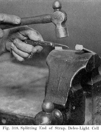
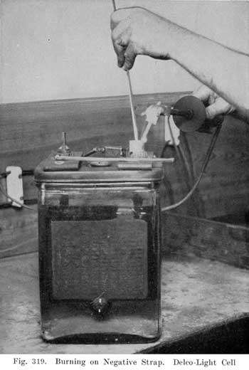
Place the strap to be burned in a vise and split the end through the center and then bend the two halves over to form a foot, as shown in Fig. 318. Make a mould out of a piece of tin or galvanized iron and place this mould around the post to which this strap is to be burned. (Fig. 319.) Then proceed to burn the post and strap together.
When a union is made between the strap and the post a small amount of new clean lead should be burned on the top of the foot to reinforce this point. Care should be taken not to get the mould too high, as this will cause trouble in getting the carbon down to the foot and the post.
How to Eliminate Burning on Straps by Use of an Auxiliary Strap
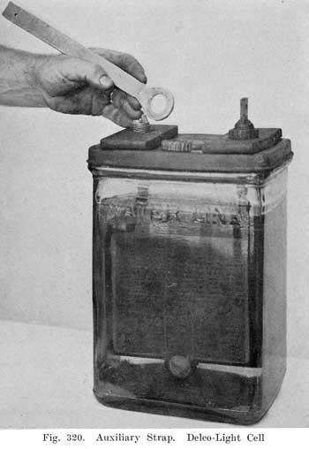
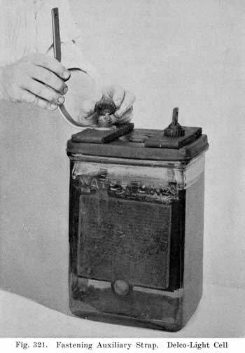
A very good way to repair broken straps without the burning operation is to use the auxiliary strap shown in Fig. 320. This strap is slipped over the post of the terminal or strap which is broken and the sealing nut is then clamped down on the strap, as shown in Fig. 321. These straps may be obtained from the Delco-Light Distributors or from the Delco-Light factory at Dayton, Ohio.
Burning on New Plates
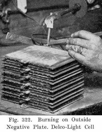
When it is necessary to burn on new plates, carefully clean with a file the lead on both the plate and the common strap to which all plates of the group are attached. Block up the plate with thin boards or wood separators until it is spaced the proper distance from the adjacent plate. Care should be taken to see that the side and bottom edge of the plate to be burned on is in line with the other plates of the group. Proceed to burn on the plate by drawing a small blaze or are and do not attempt to burn with just a glowing carbon. (Fig. 322.)
If only a glowing carbon is used the result will be a smeary mass and in the majority of cases will not hold, due to the fact that it is not welded but simply attached in one or two points.
The principle of lead burning is to weld or burn two parts into one solid mass and not merely attach one to the other.
Keeping Wood Separators In Stock
No wood separators should be used except those furnished by the Delco-Light Company. These should be kept in distilled water, to which has been added 1.220 electrolyte in the proportion of one part to ten parts of water. It is advisable whenever possible to use new separators when making repairs on a cell. Separators which have been in service are liable to be damaged by handling.
Freezing Temperature of Electrolyte
The freezing temperatures of electrolyte in the Delco-Light batteries depends upon the specific gravity of the battery. The Delco-Light battery fully charged, with a specific gravity of 1.220, should not freeze above a temperature of 30 degrees below zero. Since, however, the freezing point rises very rapidly with a decrease in specific gravity, special care should be taken to keep batteries charged when temperatures below zero are encountered. The following table shows freezing temperatures of several different gravities of electrolyte.
Specific Gravity Freezing Point
1.100 19° F. above zero.
1.150 5° F. above zero.
1.175 6° F. below zero.
1.200 16° F. below zero.
1.220 31° F. below zero.
At the temperature given, the electrolyte does not freeze solid, but forms a slushy mass of crystals, which does not always result in jar breakage.
Care of Cells in Stock
Frequently a Dealer or Distributor will have several sets of new batteries in stock for five or six months. In this case, the cells should be given a freshening charge before putting into service. This charge should consist of charging the cells to maximum gravity.
Cells received broken in transit or cells sent in for repairs should be repaired and charged as soon as possible and put into service immediately. This eliminates the possibility of the cells standing idle over a long period in which they would need a freshening charge before they could be used.
However, if such cells must be kept in stock, they can be maintained in a healthy condition by keeping on charge at a one fifth ampere rate for 13-plate cells and one-tenth ampere rate for 7-plate cells.
Taking Batteries Out of Commission
If a battery is not to be used at all for a period not longer than about 9 months, it can be left idle if it is first treated as follows: Add sufficient water to bring the electrolyte up to the water line in all cells and then give an equalizing charge, continuing the charge until the specific gravity of each cell is at a maximum, five consecutive hourly readings showing no rise in gravity. As soon as this charge is completed, take out the battery fuse and open up one or two of the connections between cells so that no current can be taken from the battery. Have vent plugs in place to minimize evaporation.
If the battery is to be taken out of commission for a longer time than 9 months, the battery should be fully charged as above and the electrolyte poured off into suitable glass or porcelain receptacles. The plates should immediately be covered with water for a few hours to prevent the negatives heating, after which the separators should be removed, the water poured out of the jars, and the positive and negative groups placed back in the jar for storage. Examine the separators. If they are cracked or split they should be thrown away. If in good condition they should be stored for further use in a non-metallic receptacle and covered with water, to which has been added electrolyte of 1.220 specific gravity, in the proportion of one part electrolyte to ten of water by volume.
Putting Batteries Into Commission After Being Out of Service
When putting batteries into commission again, if the electrolyte has not been withdrawn, all that is necessary is to add water to the cells if needed, replace connections, and give an equalizing charge.
If the electrolyte has been withdrawn and battery disassembled, it should be reassembled, taking care not to use cracked, split or dried-out separators, and then the cells should be filled with the old electrolyte, which has been saved, provided no impurity has entered the electrolyte. After filling, allow the battery to stand for 12 hours and then charge, using 6 amperes for KXG-7 size and 12 amperes for the KXG-13 size. Charge at this rate until all cells start gassing freely or temperature rises to 110° F. Then reduce the charging rate one-half, and continue at this rate until the specific gravity is at a maximum, five consecutive hourly readings showing no rise in gravity. At least 40 hours will be required for this charge. To obtain these low rates with the Delco-Light plant, lights or other current-consuming devices must be turned on while charging.
General Complaints from Users and How to Handle Them.
1. Pilot balls do not come up.
This condition may be caused by
(a) Battery discharged. (b) Weak electrolyte caused by spillage in shipment. (c) Defective ball.
Question the user to determine whether the ball will not come up if the pilot cell is bubbling freely. Weak electrolyte or a defective ball will require a service trip to determine the one which is responsible for the ball not rising. (See page 470.)
2. Lights dim-must charge daily.
This condition may be caused by
(a) Discharged battery. (b) Loose dirty connections in battery or line. (c) Low cells in battery.
The user should be questioned to determine whether the battery is being charged sufficiently. In case the user is positive the battery is charged, the next probable trouble would be that there were some loose or dirty connections in either plant or battery. Have the user check for loose connections. Should it be necessary to make an inspection trip, instruct the user to give battery an equalizing charge so the battery will be fully charged when the inspection is made.
Low cells can be checked by asking the user if all of the cells bubble freely when equalizing charge is given. In case user claims several cells fail to bubble, an inspection trip would be necessary to determine the trouble. (See page 470.)
3. Cells bubbling when on discharge.
This complaint would indicate a reversed cell. (See page 483.)
4. Cells overflowing on charge.
This would mean that the cells were filled too high above water lines.
5. Engine cranks slowly but does not fire.
This would indicate over-discharged battery. Explain to user how to start plant under this condition.
6. Plant will not crank.
This might be caused by
(a) Blown battery fuse. (b) Battery over-discharged. (c) Loose or broken connection on battery or switchboard.
OTHER EXIDE FARM LIGHTING BATTERIES
The Exide type is shown in Figure 296. The plates are held in position both by the cover and by soft rubber support pieces in the bottom of the jar. The support pieces are provided with holes in which projections on the bottom of the plates are inserted. The cover is of heavy moulded glass. The separators are of grooved wood in combination with a slotted rubber sheet (Fig. 297). The strap posts are threaded and are clamped to the cover by means of alloy nuts. The cover overlaps the top of the jar to which it is sealed with sealing compound. The method of sealing and unsealing is practically the same as in the Exide Delco-Light Type.
Batteries with Open Glass Jars
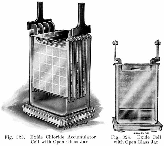
Batteries with open glass jars, in addition to the conducting lug, have two hanging lugs for each plate. The plates are hung from the jar walls by these hanging lugs, as shown in Figs. 323 and 324. The plate straps, instead of being horizontal are vertical and provided with a tail so that adjacent cells may be bolted together by bolt connectors through the end of the tail.
1. The Exide Cell is shown in Fig. 324. It has a grooved wood separator between each positive and negative plate. The separators are kept from floating up by a glass "hold-down" laid across the top. The separators are provided at the top with a pin which rests on the adjoining plates. The pins together with the plate glass hold-downs keep the separators in Position.
To remove an element it is simply necessary to unbolt the connectors, remove the glass cover and hold-down and lift wit the element.
2. The Chloride Accumulator cell is shown in Fig. 323. It differs from the Exide only in type of plates and separators. The positive plates are known as Manchester positives and have the active material in the form of corrugated buttons which are held in a thick grid, as shown in Fig. 325. The buttons are brown in color, the same as all positive active material.
The separators, instead of being grooved wood, am each a sheet of wood with six dowels pinned to it.
The element is removed the same as in the Exide type.
Batteries with Sealed Rubber Jars
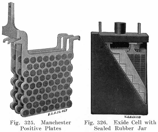
1. The Exide cell is shown in Fig. 326. It is assembled similar to Exide starting and lighting batteries, except that the plates are considerably thicker, wood and rubber separators are used, and the terminal posts are shaped to provide for bolted instead of burned-on connection. The method of sealing and unsealing the cells is the same as in Exide starting and lighting batteries.
All instructions already given for glass for cells apply to rubber jar cells except for a few differences in assembling and disassembling.
Care should be taken to keep the water level at least 1/2 inch above plates at all times as the evaporation is very rapid in rubber jar cells.
The temperature should be watched on charging to prevent overheating. Never allow temperature to go above 110° F.
Unlike the glass jar cells the sediment space in the rubber jar is not sufficient to take care of all the active material in the positive plates. On repairs, therefore, always clean out the sediment and prevent premature short circuits.
WESTINGHOUSE FARM LIGHTING BATTERIES
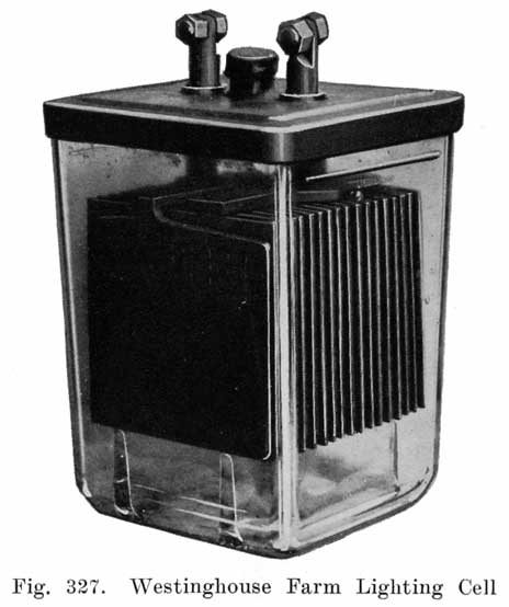
Jars. Westinghouse Farm Lighting Battery jars are made of glass, with a 5/16 inch wall. The jars are pressed with the supporting ribs for the elements an integral part from a mass of molten glass. A heavy flange is pressed around the upper edge to strengthen the jar.
Top Construction. A sealed-in cover is used similar to that used in starting and lighting batteries. The opening around the post hole is sealed with compound.
Plates. Pasted plates are used. The positives are 1/4 inch thick, and the negatives 3/16 inch. Posts are 13/16 inch in diameter.
Separators. A combination of wood and perforated rubber sheets is used.
Opening and Setting-Up Westinghouse Farm Lighting Batteries
It is preferable that the temperature never exceed 100 deg. Fahrenheit nor fall below 10 deg. in the place where the battery is set up. If the temperature is liable to drop below 10 degrees the battery should be kept in a fully charged condition.
1. Remove all excelsior and the other packing material from the top of the cells. Take cells out carefully and set on the floor. Do not drop or handle roughly. Be sure to remove the lead top connectors from each compartment.
2. Cells should be placed 1/4 inch apart. Also, cells should be placed alternately so that positive post of one cell is adjacent to negative post of the next cell. Positive post has "V" shape shoulder and the negative post has a square shoulder.
3. Grease all posts, straps and nuts with vaseline.
4. Connect positive posts of each cell to negative post of adjacent cell, using top connectors furnished. Top connectors are made so as to fit when connection is made between positive post of one cell and negative post of next cell. Use long connector between end cells of upper and lower shelves.
5. With all connections between cells in position, join the remaining positive post with a connection marked "Positive" leading from the electric generator. Do likewise with the remaining negative post.
6. If liquid level in any cell is 1 inch or more below the "Liquid Line" on side of glass jar, some liquid has been spilled and must be replaced. This should be done by an experienced person.
7. Immediately after installation operate electric generator and charge battery until gas bubbles rise freely through the liquid in all cells. A reading with the hydrometer syringe which is furnished with the battery should be taken, When the hydrometer float reads between 1.240 and 1.250, the battery is fully charged.
8. The time required to complete the charging operation mentioned above may vary from one to several hours, depending upon the length of time the battery has been in transit. During the charge the temperature of the cells should not be permitted to rise above 110 deg. Fahrenheit. If this condition occurs discontinue the charge or decrease the charge rate until cells have cooled off.
9. When charge is complete replace vent plugs.
The Relation Between Various Sizes of Westinghouse Farm Light Batteries and Work to be Done
The size of the battery furnished with complete farm lighting units vary greatly. Sometimes the battery size is varied with the size of the engine and generator, while again the same size of battery may be used for several sizes of engines and generators. In making replacements, while it is always necessary to retain the same number of cells, it is not necessary to retain the same size of cells.
Usually increasing the cell size increases the convenience to the owner and prolongs the life of the battery to an amount which warrants the higher cost.
With a larger battery, danger of injury through overcharging is lessened, the load on the battery is more easily carried and the engine and generator operate less frequently.
In order to give an idea of various battery capacities, below is a table showing the number of 32 volt, 25-watt lamps which may be lighted for various lengths of time from sixteen cells. The number of hours shows the length of time that the lamps will operate.
Table A
Type 3 Hours 5 Hours 8 Hours
G-7 22 Lamps 14 Lamps 10 Lamps
G-9 28 Lamps 19 Lamps 13 Lamps
G-11 32 Lamps 24 Lamps 15 Lamps
G-13 41 Lamps 29 Lamps 19 Lamps
G-15 47 Lamps 33 Lamps 22 Lamps
G-17 54 Lamps 38 Lamps 25 Lamps
Note:—Based on 32-Volt 25-Watt Lamps.
For example — The table shows opposite G-7 that, with the battery fully charged, twenty-two lamps may be lighted for three hours, fourteen lamps for five hours and ten lamps for eight hours, by a sixteen cell G-7 battery, without operating the engine and generator.
Motors for operating various household and farm appliances are usually rated either in horsepower or watts. The following table will give a comparison between horse-power and watts as well as the number of 25-watt lamps to which these different sizes of motors and appliances correspond.
Table B
H.P. of Motor No. of Watts Corresponding No. of 25-Watt Lamps
1/8 93 4
1/4 185 7
1/2 373 15
3/4 559 22
1 H.P. 746 30
From table B it will be seen, for example, that a one horsepower motor draws from the battery 373 watts or the same power as do fifteen 25-watt lamps. Then referring to table A, it will be found that a G-11 battery could operate 15 lamps or this motor alone for 8 hours.
Due to the fact that a motor or electric appliance may become overloaded and therefore actually use many more watts than the name plate indicates, it is not advisable to operate any motor of over 1/4 H. P. or even an appliance of over 186 watts on the G-13 or smaller sizes unless the engine and generator are running.
It is safe, however, to operate motors or other appliances up to 375 watts on the G-15 or G-17 batteries without operating the engine and generator.
WILLARD FARM LIGHTING BATTERIES
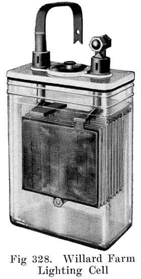
The Willard Storage Battery Co. manufactures farm lighting batteries which use sealed glass jars, or sealed rubber jars. Those using the sealed glass jars include types PH and PA. The sealed rubber jar batteries include types EM, EEW, IPR, SMW, and SEW. Both types of batteries are shipped fully charged and filled with electrolyte, and also dry, without electrolyte. The following instructions cover the installation and preparation for service of these batteries.
Glass Jar Batteries. Fully Charged and Filled With Electrolyte
Each sixteen cell set of batteries is packed in two shipping crates.
One crate, which is stenciled "No. 1" contains:
8 Cells.
18 Bolt Connectors.
1 Hydrometer Syringe.
1 Instruction Book.
The other crate which is stenciled "No. 2" contains: 8 Cells
(NOTE:--If the batteries are re-shipped by the manufacturer or distributor, care must be exercised to see that they are sent out in sets.)
Unpacking
Remove the boards from the tops of the shipping crates and the excelsior which is above the cells.
To straighten the long top connector, grasp the strap firmly with the left hand close to the pillar post and raise the outer end of the strap until it is in an upright position. Do not make a short bend near the pillar post. Lift the cells from the case by grasping the glass jars. Do not attempt to lift them by means of the top connectors.
Clean the outside of the cells by wiping with a damp cloth.
Inspection of Cells.
Inspect each cell to see if the level of the electrolyte is at the proper height. This is indicated on the jar by a line marked LIQUID LINE.
If the electrolyte is simply a little low and there is no evidence of any having been spilled (examine packing material for discoloration) add distilled or clean rain water to bring the level to the proper height.
If the liquid does not cover the plates and the packing material is discolored, it indicates that some or all of the electrolyte has been lost from the cell either on account of a cracked jar or overturning of the battery.
If only a small quantity of electrolyte is lost through spilling, the cell should be filled to the proper height with electrolyte of the same specific gravity as in the other cells. This cell should then be charged until the gravity has ceased rising. If all the electrolyte is lost write to the Willard Storage Battery Co., Cleveland, Ohio, for instructions.
Connecting the Cells
Each cell of the type PH battery is a complete unit, sealed in a glass jar. The cells are to be placed side by side on the battery rack so that the positive terminal of one cell (long connecting strap) can be connected to the negative terminal (short strap) of the adjacent cell.
Join the positive terminal of one cell to the negative terminal of the adjacent cell and continue this procedure until all the cells are connected together. This will leave one positive and one negative terminal of the battery to be connected respectively to the positive and negative wires from the switchboard. The bend in the top connector should be made about one inch above the pillar post to eliminate the danger of breakage at the post.
In tightening the bolts do not use excessive force, as there is liability of stripping the threads.
Give the battery a freshening charge before it is put in service. Type PH cells have a gravity of 1.250 when fully charged, and 1.185 when discharged.
Willard Glass Jar Batteries Shipped "Knock-Down."
Each sixteen cell set of Batteries consists of:
16 Glass Jars.
16 Positive Groups.
16 Negative Groups.
16 Covers.
16 Vent Plugs.
32 Lead Collars.
32 Lead Keys.
32 Soft Rubber Washers.
32 Hard Rubber Rods.
64 Hard Rubber Nuts.
18 Bolt Connectors.
Wood Insulators (the quantity depends upon the size of the cells).
Sealing Compound.
Hydrometer.
Instruction Books.
Electrolyte is not supplied with batteries shipped in a knockdown condition.
Examine all packing material carefully and check the parts with the above list.
Cleaning the Glass Jars
Wash the glass jars and wipe them dry.
Preparing the Covers
Wash the covers and scrub around the under edge to remove all dust. After they are thoroughly dry place them upside down on a bench.
Melt the sealing compound and pour it around the outer edge to make a fillet in the groove.
Assembling the Element and Separators
Place the plates of a positive group between the plates of a negative group and lay the element thus formed on its edge, as shown in Fig. 329.
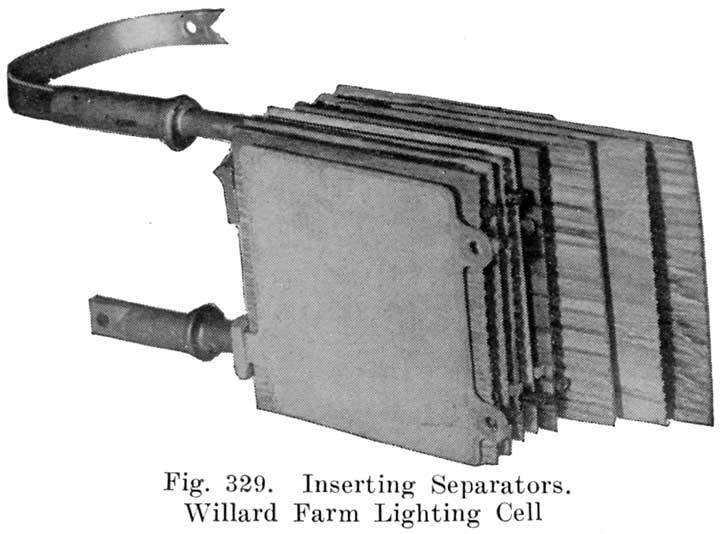
Next insert a wood separator between each of the positive and negative plates.
Next insert the hard rubber rods through the holes in the lugs of the end negative plates, and screw on the nuts. Do not screw the nuts so tight as to make the plates bulge out at the center. The rod should project the same amount on each side of the element.
Place the element in a vertical position.
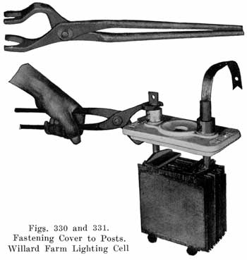
The cover can now be placed over the posts. Slip a rubber washer and a lead collar over each post. The two key holes in the lead collar are unequal in size. The collar must be placed over the post so that the end which measures 3/16 inch from the bottom of the holes to the end of the collar will be next to the rubber washer. Dip the lead key in water and then put it through the holes, having the straight edge of the key on the bottom side. This operation can easily be done by using a pair of tongs (see Figs. 330 and 331) to compress the washer. After the keys are driven tight they can be cut off with a pair of end cutters and then smoothed with a file.
Sealing Element Assembly in Jar
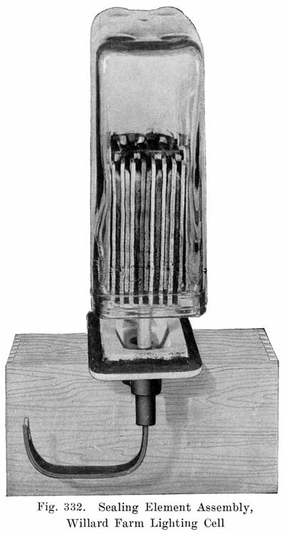
Turn the element upside down and place over a block of wood so that the weight is supported by the cover. (See Fig. 332.)
Heat the sealing compound by means of a flame (a blow torch will answer the purpose), and place the jar over the element, as shown in Fig. 331. The jar should be firmly pressed down into the compound. With a hot putty knife, clean off any compound which has oozed out of the joint. The assembled cell can now be turned to an upright position.
In case it is necessary to remove a cover, heat a wide putty knife and run it around the edge between the cover and the glass jar. This will soften the compound so that the cover can be pried off.
If it is necessary to remove the cover from the posts, the keys must be driven out by pounding on the small end, as the keys are tapered-and the holes in the lead collars are unequal in size.
Filling with Electrolyte
Fill the cells with 1.260 specific gravity electrolyte at 70° F. to the LIQUID LINE marked on the glass jars. (About I inch above the top edge of separators.) Allow the cells to stand 12 hours, and if the level of the electrolyte has lowered, add sufficient electrolyte to bring it to the proper height.
Initial Charge
Connect the positive terminal (long strap) of one cell to the negative terminal (short strap) of the adjacent cell and continue this procedure until all the cells are connected together. This will leave one positive and one negative terminal to be connected respectively to the positive and negative wires from the charging source.
The bends in the top terminal connectors should be made about one inch above the pillar posts to eliminate the danger of breakage at the post.
In tightening the bolts, do not use excessive force, as there is liability of stripping the threads.
After the cells have stood for 12 hours with electrolyte in the jars, they should be put on charge at the following rates:
Type Amperes
PH-7 4
PH-9 5
PH-11 6-1/4
PH-13 7-1/2
PH-15 9
PH-17 10
They should be left on charge continuously until the specific gravity of the electrolyte reaches a maximum and remains constant for six hours. At this point, each cell should be gassing freely and the voltage should read about 2.45 volts per cell, with the above current flowing.
Under normal conditions it will require approximately 80 hours to complete the initial charge. The final gravity will be approximately 1.250. If the gravity is above this value, remove a little electrolyte and add the same amount of distilled water.
If the gravity is too low, remove a little of the electrolyte and add the same amount of 1.400 specific gravity acid and leave on charge as before.
After either water or acid has been added, charge the cells three hours longer in order to thoroughly mix the solution, and if at the end of that time the gravity is between 1.245 and 1.255, the cells are ready for service.
It is very important that the initial charge be continued until the specific gravity reaches a maximum value, regardless of the length of time required. The battery must not be discharged until the initial charge has been completed.
If it is impossible to charge the battery continuously, the charge can be stopped over night, but must be resumed the next day.
It is preferable to charge the battery at the ampere rate given above, but if this cannot be done, the temperature must be carefully watched so that it does not exceed 110° F.
Wilard Rubber Jar Batteries Shipped Completely Charged and Filled with Electrolyte
Immediately upon receipt of battery, remove the soft rubber nipples and unscrew the vent plugs.
The soft rubber nipples are to be discarded, as they are used only for protection during shipment. Inspect each cell to see whether the electrolyte is at the proper height.
If the electrolyte is simply a little low and there is no evidence of any having been spilled (examine packing material for discoloration), add distilled water to bring the level to the proper height.
If electrolyte does not cover the plates and the packing material is discolored, it indicates that some or all of the electrolyte has been lost from the cell, either on account of cracked jar or overturning of the battery.
If only a small quantity of electrolyte is lost through spilling, the cell should be filled to the proper height with electrolyte of the same specific gravity as in the other cells. This cell should then be charged until the gravity has ceased rising, If all the electrolyte is lost, write to the Willard Storage Battery Co., Cleveland, Ohio, for instructions.
Place batteries on rack and connect the positive terminal of one crate to the negative terminal of the next crate, using the jumpers furnished.
The main battery wires from the switch board should be soldered to the pigtail terminals, which can *then be bolted to the battery terminals. Be sure to have the positive and negative battery terminals connected respectively to the positive and negative generator terminals of switchboard.
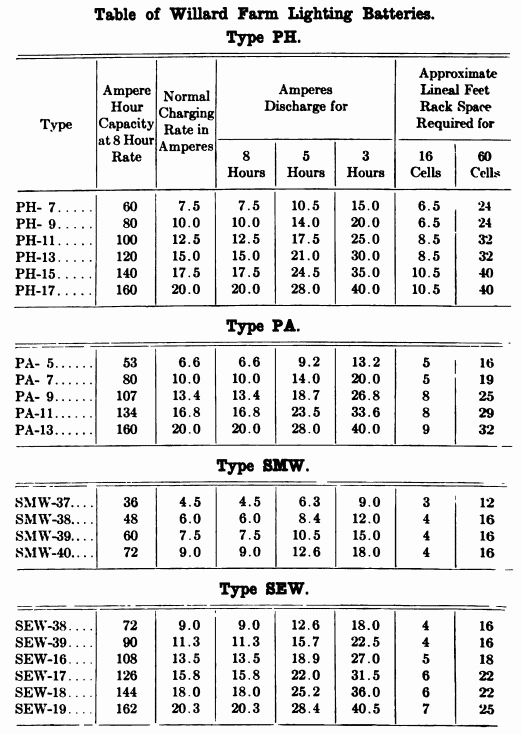
Before using the battery, it should be given a freshening charge at the rate given on page 510.
The specific gravity of the rubber jar batteries is 1.285-1.300 when fully charged, and 1.160 when discharged.
Willard Rubber Jar Batteries Shipped Dry (Export Batteries)
Batteries which have been prepared for export must be given the following treatment:
Upon receipt of battery by customer, the special soft rubber nipples, used on the batteries for shipping purposes only, should be removed and discarded.
Types SMW and SEW batteries should at once be filled to bottom of vent hole with 1.285 specific gravity electrolyte at 70° F.
In mixing electrolyte, the acid should be poured into the water and allowed to cool below 90° F. before being put into the cells. If electrolyte is shipped with the battery, it is of the proper gravity to put into the cells.
Immediately after the batteries are filled with electrolyte, they must be placed on charge at one half the normal charging rate given on page 510, and should be left on charge continuously until the specific gravity of the electrolyte stops rising. At this point, each cell should be gassing freely and the voltage should read at least 2.40 volts per cell with one-half the normal charging current flowing.
If during the charge the temperature of the electrolyte in any one cell exceeds 105° F., the current must be reduced until the temperature is below 90° F. This will necessitate a longer time to complete the charge, but must be strictly adhered to.
Under normal conditions it will require approximately 80 hours to complete the initial charge. The final gravity of the types SMW and SEW will be approximately 1.285. If the gravity is above this value, remove a little electrolyte and add same amount of distilled water while the battery is left charging (in order to thoroughly mix the solution), and after three hours, if the electrolyte is within the limits, the cell is ready for service. If the specific gravity is below these values, remove a little electrolyte and add same amount of 1.400 specific gravity electrolyte. Leave on charge as before. The acid should be poured into the water and allowed to cool below 90° P. before being used. The batteries are then ready for service.
Installing Counter Electromotive Force Cells
Counter EMF cells, if used with a battery, are installed in the same manner as regular cells. They are connected positive to negative, the same as regular cells, but the negative terminal of the CEMF group is to be connected to the negative terminal of the regular cell group. The positive terminal of the counter CEMF group is then to be connected to the switchboard.
(Table of) Contents