“A SCENE IN VENICE.”
Reading edition
The mechanical device called “A Scene in Venice” consists of a reproduction of the Trocadero palace, before which constantly passes a procession of floats or gondolas. The following diagram shows a ground plan of the framework of this window.
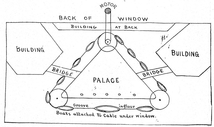
A procession of floats bearing dolls dressed as gondoliers, etc., passes constantly around the palace. The interior of the building was lit by colored electric lights. Six thousand handkerchiefs were used in this display, but the palace may be trimmed with linens or other goods.
MECHANICAL FAN.
106
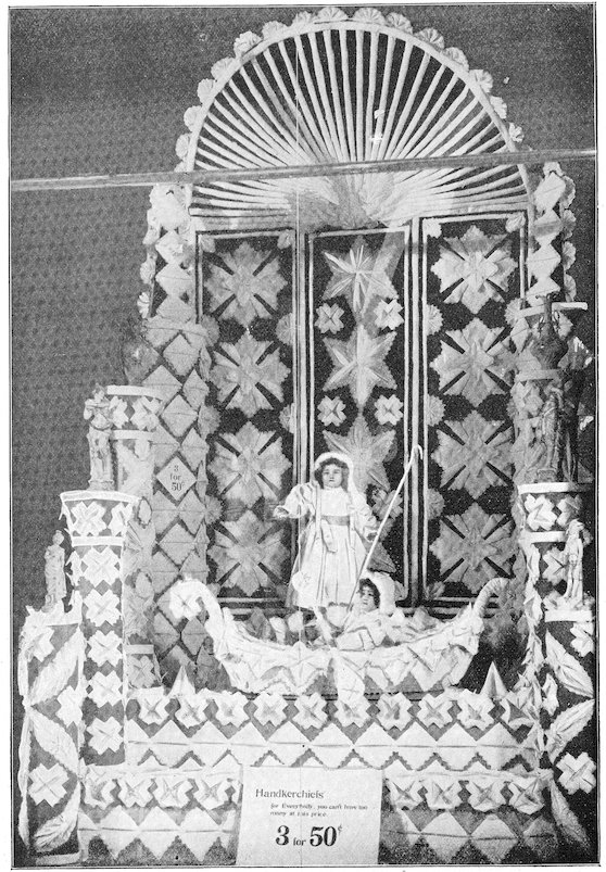
DESIGN SHOWING MECHANICAL BOAT.—Morton.
107
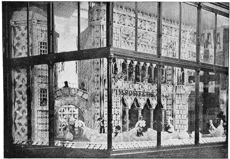
A SCENE IN VENICE.—Morton.
108This display was arranged with a high grille at top, supported by columns resting upon a pedestal or base. Upon this an enormous fan opened and closed every fifty seconds. When opened out, only the fan was visible; when folded, the fan seemed suspended at one side, revealing a 5-foot circle, studded with lights and covered with roses, in the center of which was a bust figure. On each side of the circle was a 2-foot wreath tied with white satin ribbon. The color scheme was white, top blue and ivory, with narrow moldings. Grille, fan and cornice at base were covered with dark blue velvelette. The photograph shows fan partly open and also decorations behind fan.
The ribs were fastened together with straps under the base, and also on the back of the fan, above base. Ribs were of light framework, and extended below base, as in the drawing. Front or first rib extended down three feet and had a slot through which a screw was fastened to drive wheel, which propelled it backward and forward, or, rather, from side to side; an evenly balanced weight assisted motor to open fan.
The sketch will explain mechanical apparatus.
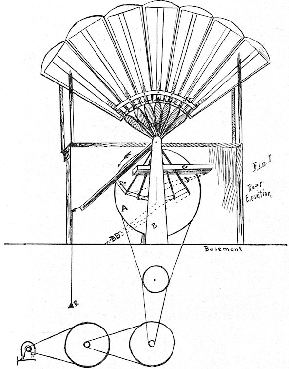
Fig. 1 shows fan, spread open, looking from back of window. A is drive wheel on a pivot, smooth side facing slot of first or front rib, and to which screw in slot is attached. B is an upright supporting rack (C) through which lower ends of all but first and last rib work to avoid wobbling. Dotted lines D are heavy rubber bands fastened to ends of second and third rib, and to end of rack, as indicated. D D are similar bands fastened to end of fourth, fifth and sixth ribs, and to floor, as in the drawing. These bands prevent sudden jerking in opening and closing. E is small weight on cord, run over pulley to basement, to assist in spreading fan. This relieves the strain on drive wheel when screw in slot is at the top. EE are straps that hold fan together, and must be proper length to allow each rib to overlap the next, in order that decorations behind fan are concealed when fan is open.
Frame of fan was covered with cambric ovals, shown in photo, which were decorated in water colors, and body was of velvelette. Rack was made of thin wood strips the proper distance apart to hold ribs in proper position. Lower portions of ribs were thicker than the upper, to prevent top from catching when closing. Iron washers were put on axle between each two ribs to reduce friction; drive wheel or one at back, was stationary, the others revolved in direction of arrow, last rib moving to and fro.
THE MECHANICAL BUTTERFLY.
This is a very novel and easily constructed device.
109
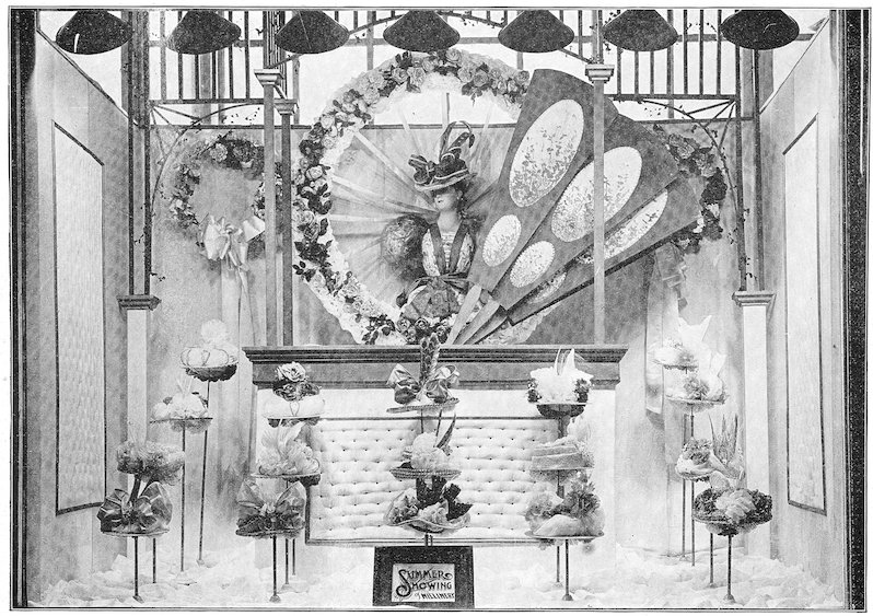
DESIGN SHOWING “THE MECHANICAL FAN.”—Walker.
110
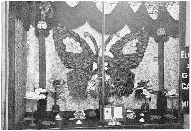
DESIGN SHOWING THE MECHANICAL BUTTERFLY.—Lundy.
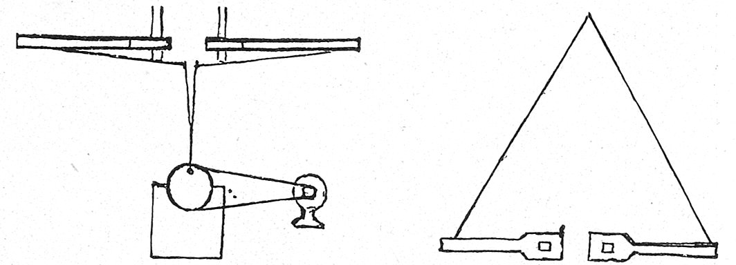
111The window was put in to show a line of black ostrich tips, and the butterfly was mechanical, opening and closing its wings in a natural manner. The background is figured cotton crepe, put on plain. The groundwork is crepe, a rich cream base with figures of heliotrope and green. In the center is placed the butterfly. It has eyes of bright green and a body of black and green. The long feelers were made of large black plumes, the ends being tipped with white plumes. The wings were made of black tips, the marking in the upper wings being of yellow, while in the lower wings are two marks, one of white and one of red. To the right is a pillar with black velvet base and a green column, and to the left a pillar with black velvet base and blue column, both pillars supporting palms. The festoon drapery is of black velvet. In front of the butterfly is a square pedestal, covered with red with a line of black velvet “lovers knots” down the center of each side. Palms and trimmed hats make up the floor decorations. We show a drawing of the mechanism used to open and close the butterfly’s wings. As the butterfly was tipped forward at the top the wings closed of their own weight. The motor is connected with a reduction gear and then with a pulley with a cam, instead of connecting direct.
The butterfly itself is 9 feet wide at the extremes and 6 feet high and is raised about two feet from the floor.
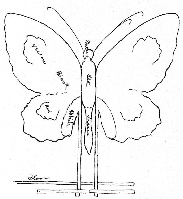
The wings of the butterfly are but the thickness of heavy pasteboard at the edge and ¾ inch towards where the wings join the body. The two one-inch rods which open the wings run through the floor to basement and are covered with same goods as background and are barely visible. On the ends of these two rods (see cut) are two levers at right angles with rod and are placed in opposition to each other. On the end of each lever is attached a cord running to a common point about 3 feet back of levers. They then go through two pulleys and combine in a single cord which is attached to a cam placed 7 inches from center of pulley. The levers being shorter than the width of a single wing, this gives the outer edge of wing a stroke of about three feet.
THE MECHANICAL EGG.
I show an illustration of a mechanical Easter window, in which the Folding Star, previously described, was used as a centerpiece. In this case, however, the points are fitted with shade rollers, making the pull from behind and out of sight. The roller springs pull it out, and the wires in.
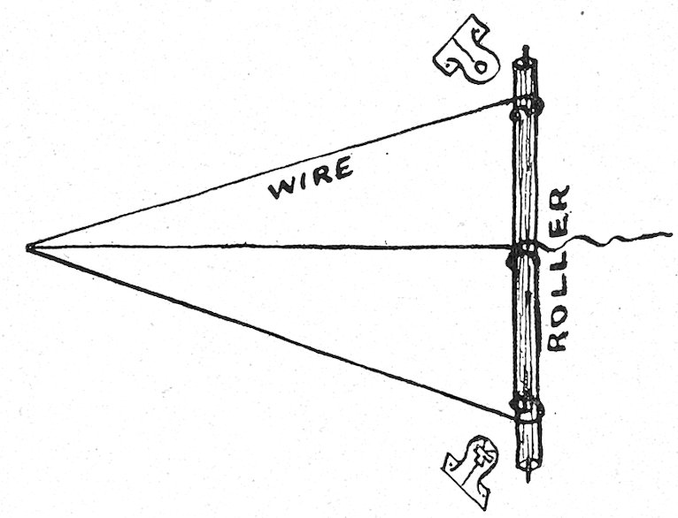
The above sketch explains the working. There was a sleeping wax infant in an egg, surrounded by light blue China silk; the other decorations were purple and white, with flowers of same shades. The points were made from wire and then covered with cloth.
The star closed every twenty-five seconds—the egg wire, being attached to the center of the two levers, had a longer pull and would begin to close before the star, and would also take a few seconds longer to open.
112
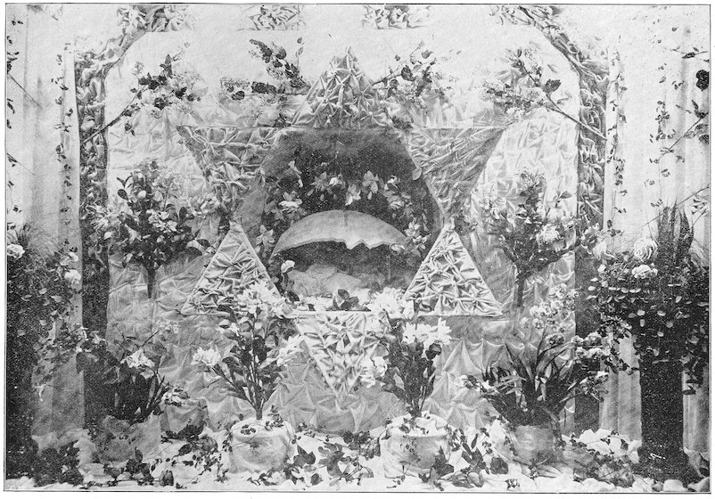
DESIGN SHOWING THE MECHANICAL EGG.—Lorch.
113The description of the egg diagram is as follows:
THE EGG DIAGRAM.
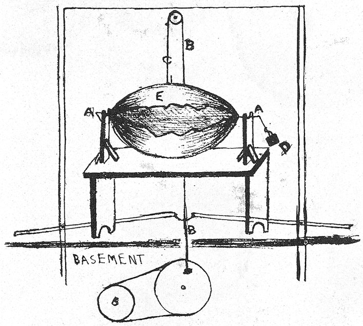
A, heavy wire axle in wood bearings; C is wire attached to back of E, top part of egg; B is some wire running to the levers; D is weight which pulls E open; when the lever pulls down it closes egg.
The egg frame was made of wire in two parts, and made of tissue paper and carpenter’s glue, painted with white zinc, and sprinkled with white flickers or diamond dust. This was made separate and then placed between star and back of window.
A PANORAMIC DISPLAY.
The mechanical feature attached to this dress goods display consists of a frame in the center of which appears a panorama of bright pictures, portraits of prominent men, etc. The frame is made of ordinary boards and puffed in two colors. In the picture shown there was an electric light in each corner of the frame. Within the frame the panorama moved constantly from top to bottom.
The panorama consists of pictures fastened together endwise upon a belt of ticking and forming an endless band about two 7-inch rollers, which are placed at the top and bottom of the background. As the rolls revolve by means of an electric motor, the pictures pass across the frame.