PLATES.
Reading edition
PLATE I.
Service Torpedo.—Pattern D.
A barrel.
B lower head.
C upper ”
g, h splices between leading-wires and detonator-wires.
K handle.
l lugs for handle.
k ” ” spindle.
i, i screw-holes for attaching circuit-closer.
n screw-rib for screw-cover.
r projection on handle shipping into spindle.
t screw-bolts securing spindle to lugs.
H spindle.
L spar leading-wires.
M water-cap.
P primer-case.
O screw-cover.
w rubber washer.
G spherical rubber packing.
D, D dry gun-cotton primer.
x detonator.
Y wet charge.
PLATE I.
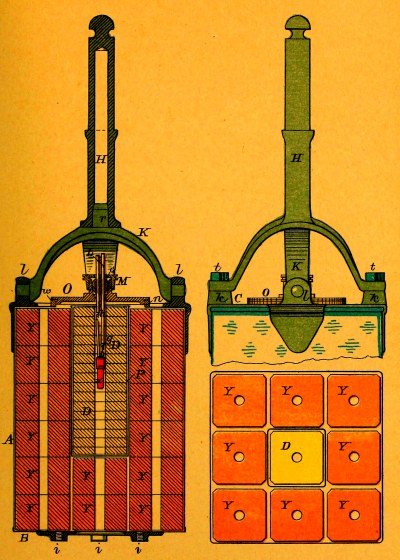
PLATE II.
Exercise Torpedo.—Pattern D.
c case.
d lower loop.
e, e loops for transportation thumb-screw and for spindle.
f throw-back hinge with thumb-screw.
H spindle.
O cover.
w rubber washer.
M water-cap.
G spherical rubber packing.
Y, Y, Y, Y wet charge.
D, D, D, D dry primer.
x detonator.
L spar leading-wires.
g, h splices between leading-wires and detonator-wires.
PLATE II.
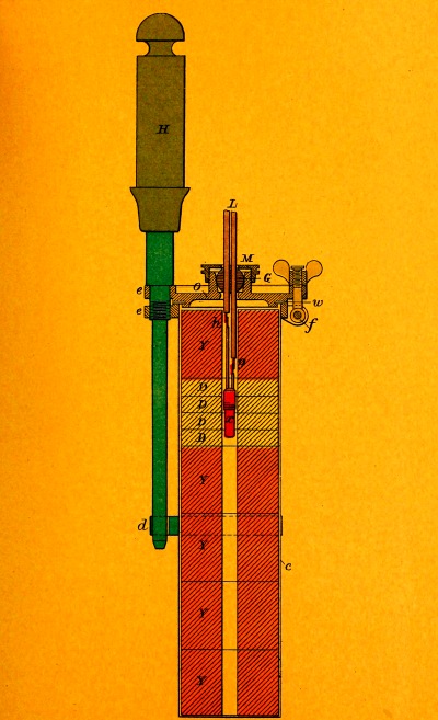
PLATE III.
Circuit-closer.—Pattern B.—Contact Torpedo.
A hollow brass casting.
M water-cap.
G spherical rubber packing.
O, O feet for attaching circuit-closer to service torpedo, Pattern D.
B inner brass plunger.
C spiral spring.
N ebonite collar.
I, I binding-posts.
E contact-springs.
t screw-cover.
s, s contact arms.
K outer plunger.
l safety-pin.
V rubber diaphragm.
k friction-plate.
PLATE III.
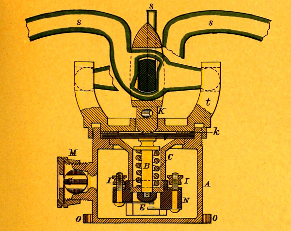
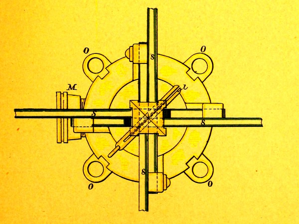
PLATE IV.
SECONDARY SPARS.
Fig. 1, Ship‘s.—Pattern A.
A main spar.
B secondary spar.
a, a spar-bands.
b key-way.
c key.
l hole for torpedo-pin.
m torpedo-pin.
PLATE IV.
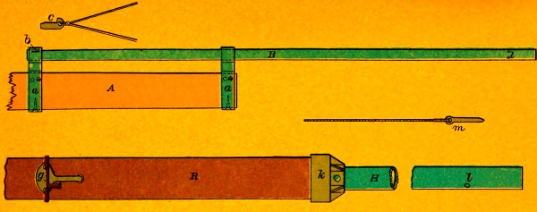
Fig. 2, Boat‘s.—Pattern A.
R main spar.
H secondary spar.
i butt.
k cap.
g toggle.
l hole for torpedo-pin.
m torpedo-pin.

PLATE V.
Contact Spar leading-Wires.—Pattern B.
B battery.
C contact torpedo.
x circuit-closer.
D contact spar leading-wires.
H hand-firing key.
S safety-break.
PLATE V.
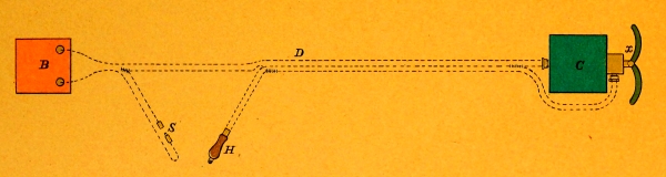
PLATE VI.
Spar-Torpedo Boat-fittings.—Pattern B.
S heel-rest.
H swivel-crutch.
R cross-beam.
D ” bearing, riveted to cross-beam and bolted through rail.
E elevating-arm.
m plate washer.
n nut on end of securing rod.
G guide-ring.
K gear on elevating-arm.
M worm.
N worm-shaft, forward length.
O ” ” after ”
X hook-coupling.
P elevating-wheel.
Q clutch.
L detaching-lever.
T torpedo.
A main spar.
B secondary spar.
PLATE VI.
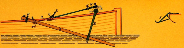
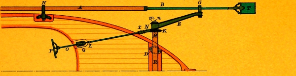
PLATE VII.
Junction of Tubes Forming Boat‘s Spar.—Pattern A.
A large tube.
B small tube.
c, c rings.
d shoulder.
e screw-holes.
f feather.
g score.
PLATE VII.


PLATE VIII.
Fig. 1, Detonator.
A copper case.
B plug.
c, c detonator-legs.
D bridge.
F gun-cotton priming.
H fulminate of mercury.
Fig. 2, Detonator Block.
A block.
B ” cover.
C, C detonators.
D, D tin box.
PLATE VIII.
Fig. 1.
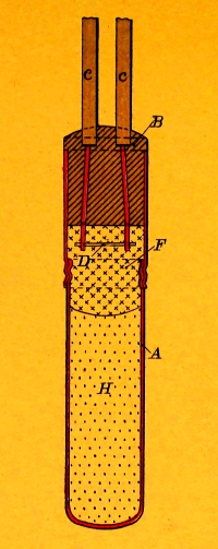
Fig. 2.
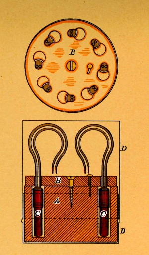
PLATE IX.
Fig. 1, Permanent Wires.
A, A electric switches (on bulwarks under bridge).
B, B forward terminals.
C, C after ”
D, D forward permanent wires.
E, E after ””
G, G permanent wires leading from bridge to lower binding-posts of electric switches.
H, H wires leading from bridge to common-return terminals, below switches.
K terminal on bridge for wires H, H.
L, L” ” ” ” ” G, G.
X firing-battery connected to terminals on bridge.
Fig. 2, Connections with Firing-key of “A” Machine.
B, B terminals of firing-key.
T, T ” ” ”
Key “T” test key.
Key “F ” firing key.
M, M wires to terminals L, L on bridge. (Fig. 1.)
N wire to terminal K on bridge (common return). (Fig. 1.)
O, O machine-connecting wires.
Fig. 3, Connections with Firing-battery.
B, B terminals of battery.
M, M wires to terminals L, L on bridge. (Fig. 1.)
N wire to terminal K on bridge (common return). (Fig. 1.)
H hand-firing key.
Plate IX.
Fig. 2.
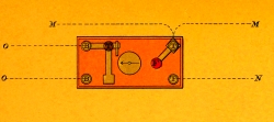
Fig. 3.
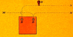
Fig. 1.
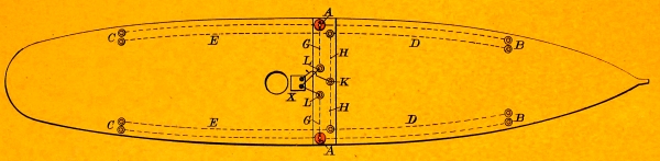
PLATE X.
Fig. 1, Electric Switch.
A permanent wire to forward torpedo.
B ”” ” after ”
C, C ”” common return.
D wire to battery or firing-key of machine.
E commutator of switch.
PLATE X.
Fig. 1.
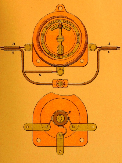
Fig. 2, Terminal.
H binding-screw.
I permanent wire.
w wire temporarily connected.
Fig. 2.
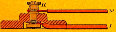
PLATE XI.
Heel-fittings for Ship‘s Spar.
a ship‘s spar.
b thrust-plate (30″ diameter).
c eye-bolt through thrust-plate and ship‘s side.
d heel-bolt.
Plate XI.
Fig. 2.
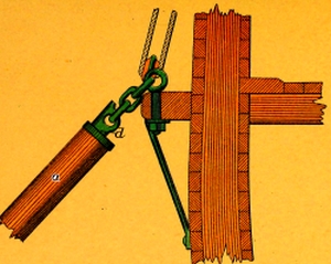
Fig. 1.
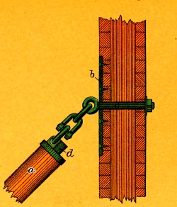
PLATE XII.
Ship’s Spar Fittings.
a ship’s spar.
b topping lift.
c forward guy.
d after ”
e span for topping lift (16′ long).
f ” ” forward guy (16′ long).
x, x, x, x bands on spar (5′ apart).
PLATE XII.
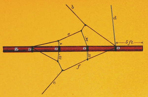
PLATE XIII.
Battery Cell.
a okonite jar.
b, b zinc cylinder.
c platinum plate.
d muslin bag filled with crushed carbon.
e ebonite disc.
f ” plug.
g sal-ammoniac solution.
h positive terminal.
i negative ”
k rubber cover.
r rubber ring.
PLATE XIII.
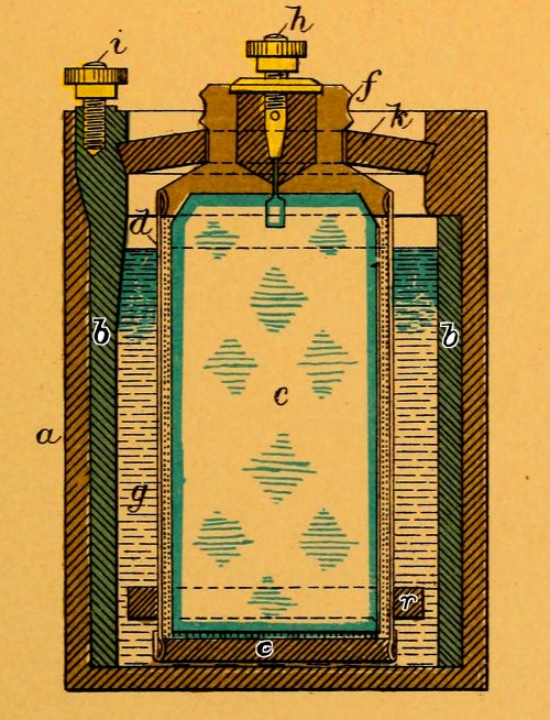
PLATE XIV.
Battery Tester.
a, a battery terminals.
b ” tester.
c fuze-bridge in tester.
PLATE XIV.
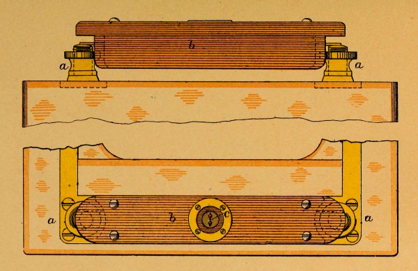
PLATE XV.
Fig. 1, Hand-firing Key.—Pattern B.
a, a hickory pieces.
c, c contact studs.
L, L leading-wires.
d rubber cot.
e safety-pin with hole for laniard.
f eye-bolt for laniard.
Fig. 2, Diagram Showing Hand-firing Key in Circuit.
B battery.
H hand-firing key.
w, w leading-wires.
PLATE XV.
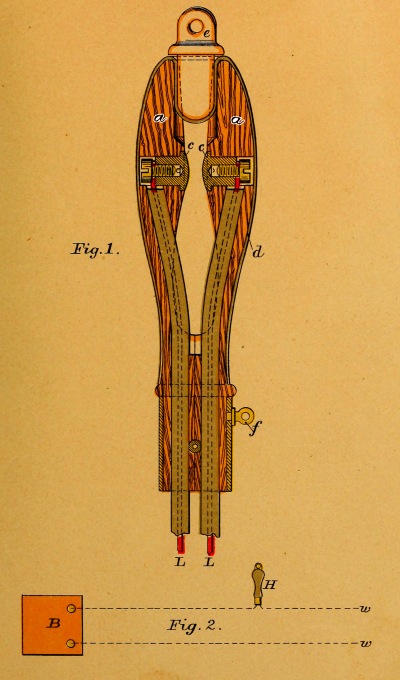
PLATE XVI.
Fig. 1, “A” Machine and Firing-key Connected.
A “A” machine.
C firing-key.
B, B terminals of firing-key.
T, T ”” ”
Key “T” test key.
” “F” firing-key.
O machine-connecting wires.
w, w wires to torpedo.
Fig. 2, “C” Machine Connected.
D “C” machine.
C firing-key (in the machine).
Key “T” test key.
” “F” firing-key.
w, w wires to torpedo.
PLATE XVI.
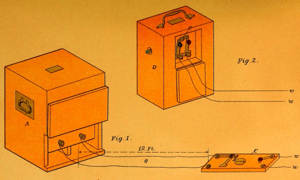
Plate XVII.
Fig. 1, firing-key, short-circuit.
” 2, ”testing circuit.
” 3, ”firing-circuit.
O, O machine-connecting wires.
w, w wires to torpedo.
B, B terminals of firing-key.
T, T ” ” ”
Key “T” test key.
Key “F” firing-key.
PLATE XVII.
Fig.1.
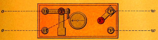
Fig.2.
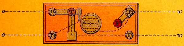
Fig.3.
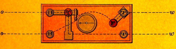
PLATE XVIII.
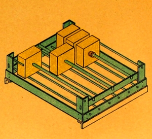
Steam-drier.
Plate XVIII.
Fig. 1.
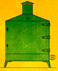
Fig. 2.
Footnotes: