THE TWO OR THREE PHASE ALTERNATING CURRENT SYSTEMS.
Reading edition
By CARL HERING.
The occasion of the transmission of power from Lauffen to Frankfort has brought to the notice of the profession more than ever before the two or three phase alternating current system, described as early as 1887-88 by various electricians, among whom are Tesla, Bradley, Haselwander and others. As to who first invented it, we have nothing to say here, but though known for some years it has not until quite recently been of any great importance in practice.
Within the last few years, however, Mr. M. Von Dolivo-Dobrowolsky, electrical engineer of the Allgemeine Elektricitats Gesellschaft, of Berlin, has occupied himself with these currents. His success with motors run with such currents was the origin of the present great transmission of power exhibit at Frankfort, the greatest transmission ever attempted. His investigation in this new sphere, and his ability to master the subject from a theoretical or mathematical standpoint, has led him to find the objections, the theoretically best conditions, etc. This, together with his ingenuity, has led him to devise an entirely new and very ingenious modification, which will no doubt have a very great effect on the development of alternating current motors.
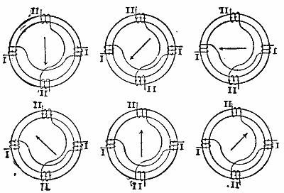
It is doubtless well known that if, as in Fig. 1, a Gramme ring armature is connected to leads at four points as shown and a magnet is revolved inside of it (or if the ring is revolved in a magnetic field and the current led off by contact rings instead of a commutator), there will be two alternating currents generated, which will differ from each other in their phases only. When one is at a maximum the other is zero. When such a double current is sent into a similarly constructed motor it will produce or generate what might be called a rotary field, which is shown diagrammatically in the six successive positions in Fig. 2. The winding here is slightly different, but it amounts to the same thing as far as we are concerned at present. This is what Mr. Dobrowolsky calls an "elementary" or "simply" rotary current, as used in the Tesla motors. A similar system, but having three different currents instead of two, is the one used in the Lauffen transmission experiment referred to above.
FIG. 1.
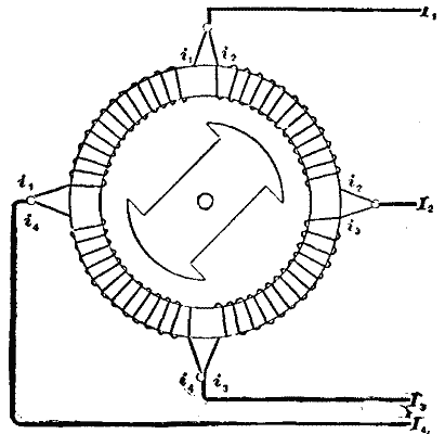
FIG. 2.
In investigating this subject Mr. Dobrowolsky found that the best theoretical indications for such a system would be a large number of circuits instead of only two or three, each differing from the next one by only a small portion of a wave length; the larger their number the better theoretically. The reason is that with a few currents the resulting magnetism generated in the motor by these currents will pulsate considerably, as shown in Fig. 3, in which the two full lines show the currents differing by 90 degrees. The dotted line above these shows how much the resulting magnetism will pulsate. With two such currents this variation in magnetism will be about 40 degrees above its lowest value. Now, such a variation in the field is undesirable, as it produces objectionable induction effects, and it has the evil effect of interfering with the starting of the motor loaded, besides affecting the torque considerably if the speed should fall slightly below that for synchronism. A perfect motor should not have these faults, and it is designed to obviate them by striving to obtain a revolving field in which the magnetism is as nearly constant as possible.
FIG. 3.
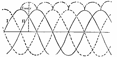
If there are two currents differing by 90 degrees, this variation of the magnetism will be about 40 per cent.; with three currents differing 60 degrees, about 14 per cent; with six currents differing 30 degrees it will be only about 4 per cent., and so on. It will be seen, therefore, that by doubling the three-phase system the pulsations are already very greatly reduced. But this would require six wires, while the three-phase system requires only three wires (as each of the three leads can readily be shown to serve as a return lead for the other two in parallel). It is to combine the advantages of both that he designed the following very ingenious system. By this system he can obtain as small a difference of phase as desired, without increasing the number of wires above three, a statement which might at first seem paradoxical.
Before explaining this ingenious system, it might be well to call attention to a parallel case to the above in continuous current machines and motors. The first dynamos were constructed with two commutator bars. They were soon found to work much better with four, and finally still better as the number of commutator bars (or coils) was increased, up to a practical limit. Just as the pulsations in the continuous current dynamos were detrimental to proper working, so are these pulsations in few-phased alternating current motors, though the objections manifest themselves in different ways—in the continuous current motors as sparking and in the alternating current motors as detrimental inductive effects.
The underlying principle of this new system may be seen best in Figs. 4, 5, 6, 7 and 8. In Fig. 4 are shown two currents, I1 and I2, which differ from each other by an angle, D. Suppose these two currents to be any neighboring currents in a simple rotary current system. Now, if these two currents be united into one, as shown in the lower part of the figure, the resulting current, I, will be about as shown by the dotted line; that is, it will lie between the other two and at its maximum point, and for a difference of phases equal to 90 degrees it will be about 1.4 times as great as the maximum of either of the others; the important feature is that the phase of this current is midway between that of the other two. Fig. 5 shows the winding of a cylinder armature and Fig. 7 that, of a Gramme armature for a simple three-phase current with three leads, with which system we assume that the reader is familiar.
FIG. 4.
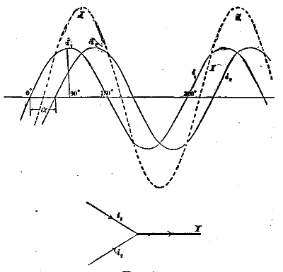
FIG. 5.
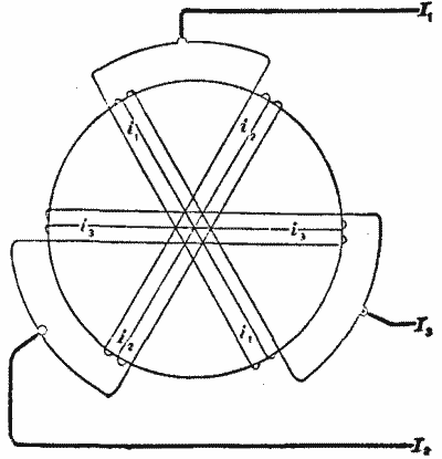
The two figures, 4 and 5 (or 7), correspond with each other in so far as the currents in the three leads, shown in heavy lines, have a phase between those of the two which compose them. Referring now to Fig. 6 (or 8), which is precisely like Fig. 5 (or 7), except that it has an additional winding shown in heavy lines, it will be seen that each of the three leads, shown in heavy lines, is wound around the armature before leaving it, forming an additional coil lying between the two coils with which it is in series. The phase of the heavy line currents was shown in Fig. 4 to lie between the other two. Therefore, in the armature in Fig. 6 (or 8) there will be six phases, while in Fig. 5 there are only three, the number of leads (three) remaining the same as before. This is the fundamental principle of this ingenious invention. To have six phases in Fig. 5 would require six leads, but in Fig. 6 precisely the same result is obtained with only three leads. In the same way the three leads in Fig. 6 might again be combined and passed around the armature again, and so on forming still more phases, without increasing the number of leads. Figs. 7 and 8 compound with 5 and 6 and show the same system for a Gramme ring instead of a cylinder armature.
FIG. 6.
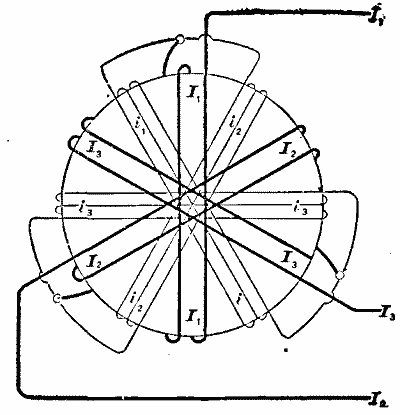
FIG. 7.
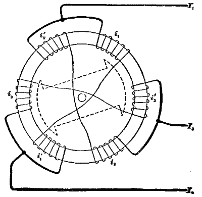
FIG. 8.
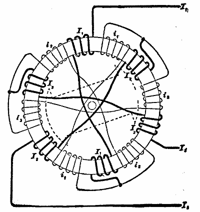
As was stated in the early part of this description, the main object in a rotary current motor is to have a magnetic field which is as nearly constant in intensity as possible, and which changes only its position, that is, its axis. But in Fig. 4 it was shown that the current I (in dotted lines) is greater than the others (about as 1.4 to 1 for a phase difference of 90 degrees). If therefore the coils in Fig. 6 or 8 were all alike, the magnetism generated by the heavy line coils would be greater than that generated by the others, and would therefore produce very undesirable pulsations in the magnetic fields; but as the magnetism depends on the ampere turns, it is necessary merely to have correspondingly fewer turns on these coils, as compared with the others. This is shown diagrammatically in Figs. 6 and 8, in which the heavy line coils have less windings than the others. In practice it is not always possible to obtain the exact ratio of 1 to 1.4, for instance, but even if this ratio is obtained only approximately, it nevertheless reduces the pulsations very materially below what they would be with half the number of phases. It is therefore not necessary in practice to have more than an approximation to the exact conditions.
FIG. 9.
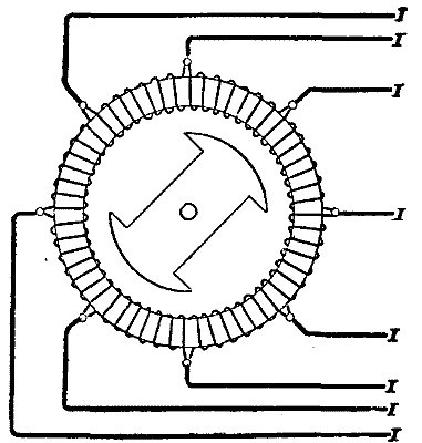
FIG. 10.
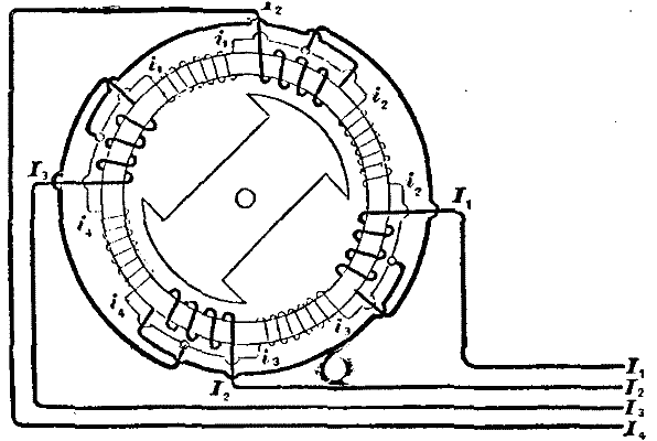
FIG. 11.
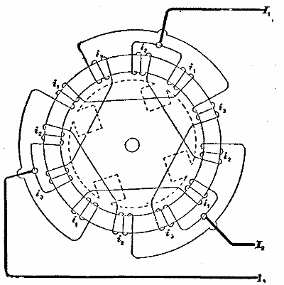
FIG. 12.
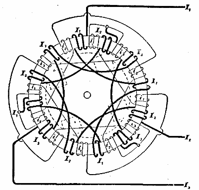
Fig. 9 shows a multiple phase armature having double the number of phases as Fig. 1, and would according to the old system, therefore, require eight leads. Fig. 10 shows the new system with the same number of phases as in Fig. 9, but requiring only four leads instead of eight. Figs. 11 and 12 correspond with Figs. 7 and 8 and show the windings for a multipolar motor in the two systems.
FIG. 13.
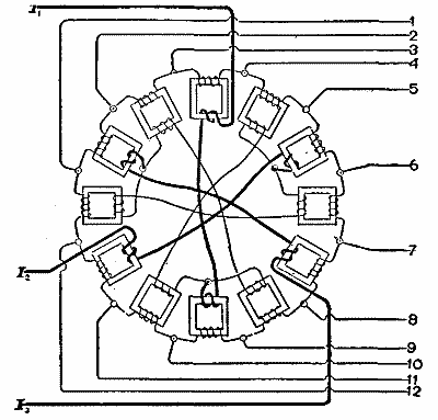
FIG. 14.
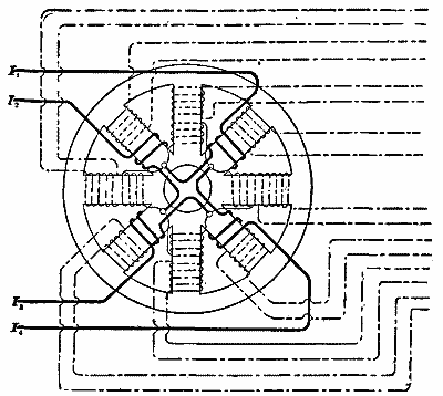
FIG. 15.
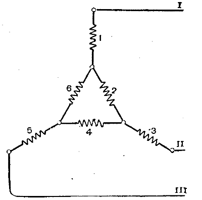
These figures show how a motor may be wound so as to be a multiple phase motor, although the current entering the motor is a simple, elementary three or two phase current, which can be transformed by means of a simple three or two phase current transformer, before entering the motor, such transformers as are used at present in the Lauffen-Frankfort transmission. But the same principle as that for the motor may also be applied to transformers themselves, as shown in Figs. 13 and 14. Fig. 13 shows a set of transformers which are fed by a simple three-phase current shown in heavy lines, and which gives in its secondary circuit a multiple phase rotary current. The connections for the primary circuit of a transformer with six coils are shown diagrammatically in Fig. 15, the numbers 1 to 6 representing the succession of the phases. Fig. 14 shows a transformer for a two-phase current with four leads, transforming into a multiple phase current of 16 leads. The transformer in this figure is a single "interlocked" transformer in which the fields are magnetically connected and not independent of each other as in Fig. 13. This has advantages in the regulation of currents, which do not exist in Fig. 13, but which need not be entered into here. The transformers used in the Lauffen-Frankfort transmission are similar, magnetically, to Fig. 14, only that they are for a simple three-phase current in both primary and secondary circuits. Attention is also called to the difference in the connections of secondary circuits in Figs. 13 and 14; in the former they are connected in a closed circuit similarly to an ordinary closed circuit armature, while in Fig. 14 they are independent as far as the currents themselves are concerned, though magnetically their cores are connected. It is not the intention to enter into a discussion of the relative values of these various connections, but merely to draw attention to the wide range of the number of combinations which this system admits of.—Electrical World.