WELDLESS STEEL CHAINS.
Reading edition
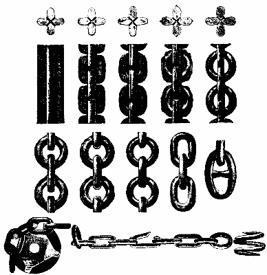
At the Royal Naval Exhibition, London, Messrs. William Reid & Co. are exhibiting their weldless steel chains, which we now illustrate.
Of the many advantages claimed for steel chains, it may be prominently noted that a very important saving of weight is effected on account of their possessing such a high breaking strain, compared with the ordinary welded iron chains. To illustrate this, it may be stated that a given length of the weldless steel chain is 35 to 40 per cent. less in weight than an equivalent length of iron chain, will stand the same breaking strain as the latter, and indeed, where steel of special quality is used in making the weldless chains, this difference can be increased as much as 70 to 80 per cent. Whereas superior iron chains break at a strain at 17 tons per square inch, these weldless steel chains will stand a strain of 28 to 30 tons, with 20 to 26 per cent. elongation.
Again, there is greater security in their use from the fact that there are no welds, and they give warning of the limit of strain to which they can bear being approached, by elongation, which can be carried to a considerable extent before the chain breaks. Moreover, over, in chains made by this process, the links are all exactly alike. Though the life of a weldless steel chain is said to be twice that of an ordinary one, the price per length is little more than that of best iron chains.
They are made in lengths of from 40 to 50 feet, being compressed from a solid rolled steel bar, the section of which is shaped like a four-pointed star. In the first place holes are pierced at intervals down the length of the bar, thus determining the length of the several links. Then the bar is notched between the holes so as to give the external form of the links. The next step is "flattening out," which presses the links into shape on their inner side, but leaves the openings still closed by a plate of metal. They are then stamped out so as to round them up, and the metal inside them is punched out, and the edges "cleaned," or trimmed off. The links are now parted from one another and stamped again, to insure equal thickness in all parts of the chain. The only processes now to be gone through are dressing and finishing. According to the die used, the shape of the links can be varied to suit any required pattern. The lengths of chain thus made are joined by spiral rings made of soft steel, the convolutions being afterward hammered together till they become solid. A ring of this description, ¾ inch diameter, underwent a strain of 46,200 lb., that is, 23 tons to the square inch, its elongation being 21 per cent.
These chains have passed satisfactorily the tests of the Bureau Veritas, and both that association and Lloyd's have accepted their use on the same conditions and under the same tests as ordinary chains.
So much for the general idea of punching steel chains. We will now describe a recent invention by which superior steel chains are produced, the author of which is Mr. Hippolyte Rongier, of Birmingham, Eng. He says:
My invention has for its object the manufacture of weldless stayed chains, whereof each link, together with its cross strut or stay, is made of one piece of metal without any weld or joint; and the invention consists in producing a chain of stayed links from a bar of cruciform section by the consecutive series of punching, twisting and stamping operations hereinafter described, the punching operations being entirely performed on the metal when in the cold state.
Figs. 1 to 10 show the progressive stages in the manufacture of the chain, and the remaining figures show the series of tools that are employed.
MANUFACTURE OF WELDLESS CHAINS.
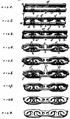
The general method of operation of making stayed chains according to my invention is so far similar to the methods heretofore proposed for making unstayed chains from the bar of cruciform section that the links are formed alternately out of the one and the other pair of diametrically opposite webs of the rod, the links, when severed and completed, being already enchained together at the time of their formation. The successive operations differ, however, in many important practical respects from those heretofore proposed, as will appear from the following detailed description of the successive steps in the process illustrated by Figs. 1 to 10.
I will distinguish the one pair of diametrically opposite webs of the bar and the notches and mortises punched therein and the links formed therefrom from the other pair by an index figure 1 affixed to the reference letters appertaining thereto.
a a are one pair of diametrically opposite webs, and a' a' the other pair of webs of the bar.
The first operation illustrated in Fig. 1 is to punch out of the edge of one of the webs, a, a series of shallow notches, b, at equal intervals apart, corresponding to the pitch of the links to be formed out of that pair of webs and situated where the spaces will ultimately be formed between the ends of that series of links. The notches are made with beveled ends, and are no deeper than is absolutely necessary (for the purpose of a guide stop in the subsequent operations, as hereinafter described), so as to avoid, as far as possible, weakening the bar transversely. This operation is repeated upon one of the pairs of webs a'; but whereas in the first operation of notching the web the "pitch" of the notches is determined by the feed mechanism, in this second operation of notching the notches, b, cut in the web, a, serve as guides to influence and compensate for any inaccuracy of the feed mechanism, so that the second set of notches, b', shall be intermediate of and rigorously equidistant from the first set of notches, b. This compensation is effected by the notches, b, fitting on to a beveled stop on the bed of the punching tool by which the notches, b', are cut, the beveled ends of the notches, b, causing the bar under the pressure of the punch to adjust itself in the longitudinal direction (if necessary) sufficiently to rectify any inaccuracy of feed. These notches, b b', similarly serve as guides to insure uniformity of spacing in the subsequent operations of punching out the links.
The second operation (illustrated in Fig. 2) is to punch out of the pair of opposite webs, a a, pairs of oblong mortises—two pairs, c c, and one pair, d d. These three pairs of mortises (which might be punched at separate operations, but are preferably punched at one stroke of the press) are situated as close as possible up to the faces of the other pairs of webs, a' a', the pairs of mortises, c c, being so spaced as to correspond in position to the eyes of the links to be formed, to which they correspond approximately in form, while the pair, d, correspond in position to the notches, b, and therefore to the intervals by which the links formed out of the same pair of webs, a a, will be separated when completed. This operation is continued along the whole length of the pair of webs, a. It will be observed that a considerable thickness of metal is left at a* between the notches, b, and the mortises, d. This is of primary importance and is one of the essential features of my method of manufacture, inasmuch as by first punching out the mortises, d, the subsequent removal of the metal from between the outer ends of the links is greatly facilitated, while by leaving the solid metal, a*, the transverse strength of the webs, a a, is not materially diminished, so that when the operation of punching the mortises, c and d, in the other pair of webs, a', is performed the bar will not be bent and crippled, as would inevitably be the case were the whole of the metal opposite the notches, b, which is ultimately to be removed, to be punched out at so early a stage of the manufacture. The operation of punching the pairs of mortises, c' and d, having been repeated along the other pair of webs, a', it will be observed that like the notches, b, the mortises, c d, in the one pair of webs alternate with those, c' d', in the other pair of webs.
The third operation (illustrated in Fig. 3) is to elongate the mortises, c d, and bring the mortises, c c', more nearly to the final form. This is performed by punches similar to but larger (in the direction of the length of the rod) than those used in the second operation.
The third operation, which is repeated upon both pairs of webs, a a a' a', may be considered as a second stage of the second operation, it being preferable to punch out the mortises in two stages in order to remove sufficient metal without unduly straining the bar.
The fourth operation (illustrated in Fig. 4) consists in roughly shaping the ends of the links externally by punching out the portions, a*, of the webs, a, between the links lying in the same plane or formed out of the same pair of webs. This operation is repeated on the other pair of webs, a'. Up to this point a continuous core of metal has been left at the intersection of the two pairs of webs.
The fifth operation (illustrated in Fig. 5) consists in punching out the portions, e, of the core at each side of the cross stay of the link, so as to separate the cross stay from the outer ends of the adjacent links. This operation is performed by removing a portion only of the metal of the core which intervenes between the cross stay and the outer ends of the adjacent links enchained with the link under operation—that is to say, portions, e*, of the core are temporarily left attached to the outer ends of the links in order to avoid crippling or bending the bar, which might occur were the whole of this metal, which is ultimately to be removed, to be punched out at once, these portions, e*, being supported by the bed die in the operation of punching out the spaces, e, as hereinafter described. This operation having been repeated upon both pairs of webs, it will be observed that the rod-like form of the chain is now only maintained by the portion of the core at the points, f, where the inner side of the eye or bow of one link is united with that of the next one. The severing of these intervening portions of the core and the breaking up of the rod into the constituent links of the chain constitute the sixth operation.
The sixth operation (illustrated in Fig. 6) is performed by torsion, and for this purpose one end of the rod is held fixed while the other is twisted once or twice in opposite directions, until by fatigue of the metal at the points, f, the whole of the links are severed almost at the same instant, and a chain of roughly formed stayed links is produced.
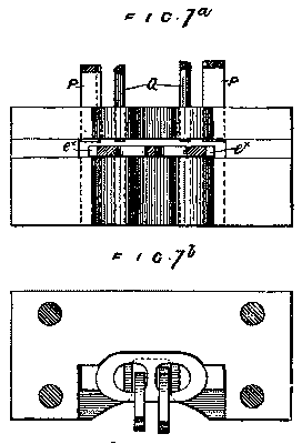
The seventh operation (illustrated in Fig. 7) is to remove the superfluous projecting pieces of metal both from the inside and outside of the ends of the links. For this purpose the two ends of each link are operated on at the same time by two pairs of punches corresponding to the outline of the ends of the link.
The eighth operation (illustrated in Fig. 8) is to bring the ends of the links to their finished rounded form. This is performed by stamping both ends of each link at the same time between pairs of shaping dies or swages.
The ninth operation (illustrated in Fig. 9) is to bring the middle portion of each link—that is to say, the side members and the cross stay—to the finished rounded form, which is also performed by means of a pair of dies or swages.
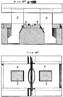
The tenth and last operation (illustrated in Fig. 10) is to contract the link slightly in the lateral direction in order to correct any imperfections at the sides left by the two previous operations and bring the link to a more perfect and stronger form, as shown. This operation has the important result of strengthening the link considerably by contracting or rendering more pointed the arched form of the bow or end of the link, and also by thickening the metal at that part where the wear is greatest, this thickening of the metal at the ends of the link occurring in the direction of the line of strain (as indicated by x in Fig. 10) and being brought about by the compression or "upsetting" of the metal at the end of the link. It may be preferable to perform this operation immediately after the seventh operation, and I reserve the right to do so.
In the case of large cables only the metal is preferably heated for the eighth, ninth, and tenth operations.
I will now refer to the figures which illustrate the series of tools whereby the above mentioned operations are performed.
Fig. 1a shows a plan (the punch being in section) and Fig. 1b an elevation of the bed die of the tool by which the notches b of the first operation are performed. The feed mechanism is not shown, but might be of any ordinary intermittent kind. g is a groove in the bed, in which lies the lower vertical web of the rod, of cruciform section, the two horizontal webs lying upon the bed with the edge of the web to be notched lying just over the die, in which works the punch, B, of which B' is the cutting edge. The punch is operated in the usual way, its lower end, which does not rise out of the die, acting as a guide. B* is the beveled stop in the groove, g, which by fitting in the notches, b or b', corrects inaccuracies of the feed.
FIG. 1a.
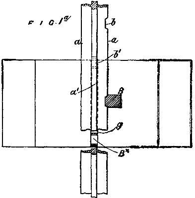
FIG. 1b.
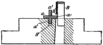
Fig. 2a is a sectional plan and Fig. 2b an elevation of the tool by which the second operation is performed, the same tool being also used for performing the third operation. (Illustrated in Fig. 3a.) h h are a pair of bed-dies having a space h' between them to receive the lower web of the bar, and having notches, C C and D D, in their inner ends, forming counterparts of the punches by which the pairs of mortises, c d, Fig. 2, are punched in the pair of webs lying upon the bed-dies, h. These bed-dies are fitted to slide a little in opposite directions upon a suitable bed plate and are caused by the inclined cams, i', on the guides, i, of the press head (which pass through corresponding apertures in the bed-dies, h) to approach each other at the moment the punches come down on the work, so as to grip the lower web of the rod and support the pair of webs being operated on close up to the sides of the lower web lying in the space h', while when the punches rise the bed-dies move apart, so that the web is quite free in said space h' and the rod may be easily fed forward for a fresh stroke of the press. B* is the beveled stop in the space, k', as in the tool first described. The bed-dies h have a second set of notches C' D' at their outer ends, similar to but longer than those C D, so that by reversing the bed-dies they will form counterparts for a second set of punches corresponding thereto for performing the third operation—i.e., enlarging the mortises, c d, as represented in Figs. 3 and 3a; or, instead of adapting the dies, h, to perform the two operations, separate tools may be used for the second and third operations.
FIG. 2a.
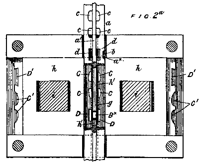
FIG. 2b.
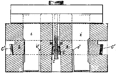
FIG. 3a.
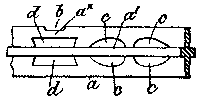
Fig. 4a is an elevation and Fig. 4b a sectional plan of the tool for performing the fourth operation—namely, removing the portion a*, Figs. 3, 3a, 4a, and 4b. This is done by a pair of punches, A*, corresponding in shape to the ends of the link in the rough and to the aperture shown in the bed-die, k, Fig. 4b, which has a groove, k', to admit the lower web of and to guide the rod. The beveled stop, B*, used in operating on the pair of webs, a, corresponds to the notches, b'; but in operating on the webs, a', the stop must be replaced by one corresponding to the aperture left by the removal of the portion, a*.
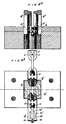
Fig. 5a is an elevation, Fig. 5b a plan, and Fig. 5c a longitudinal vertical section of the tool for performing the fifth operation, the work being shown in section in the latter figure. It consists of a bed-die, l, with groove, m, to receive the lower web, but terminating at a distance from the die apertures, so as to leave supports, n, for the parts, e*, of the rod to resist the downward pressure of the punches, E, which remove the portions, e, from each side of the cross stay, as shown in Figs. 5b and 5c. The correct position of the work in regard to the punches is insured by these supporting parts, n, which terminate the grooves, m.
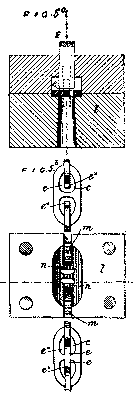
FIG. 5c.
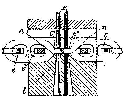
Fig. 6a is an elevation of the winch for performing the sixth operation.
FIG. 6a.
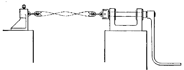
Fig. 7a is an elevation and Fig. 7b a plan of the tool for performing the seventh operation. P P are the punches for trimming the outside and Q Q those for trimming the inside of the ends of the links. The links adjacent to the one to be operated on are brought together into the position shown in dotted lines, the bed-die having an aperture in it to admit of this, so that both ends of the link to be trimmed may be operated on together.
The tool for performing the eighth operation consists of a pair of swages, the bottom one only being shown in Fig. 8a. The swages correspond to the intended rounded sectional form of the ends of the link, which is placed in position between the swages in a similar manner to that described for Fig. 7b, so that both ends are rounded or finished off at once.
FIG. 8a.
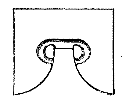
Fig. 9a is a plan of the bottom swage of the tool for performing the ninth operation, the upper swage corresponding thereto at least in so far as the middle part of the link to be operated on is concerned.
FIG. 9a.
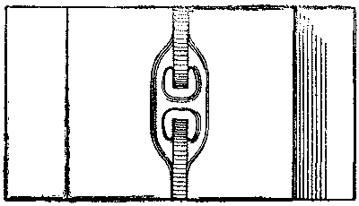
The tool for performing the tenth operation is represented in elevation and plan in Figs. 10a and 10b. It consists of a pair of bed-dies, R, fitted to slide together and operated by the cams, s, on the guide rods, S, the operation being similar to that of the tool shown in Figs. 2a and 2b, except that there are no punches, and that the link which lies in the cavity of the dies is merely compressed in the lateral direction by the inward motion of the bed-dies.
My invention further comprises a modification of the above described process, which has for its object to enable the weldless stayed links to be made as short and particularly as narrow as may be necessary in order to adapt the chain to run over the sheaves of pulley blocks and to suit other purposes for which short-link welded chain has heretofore only been available.
FIGS. 10 through 12.
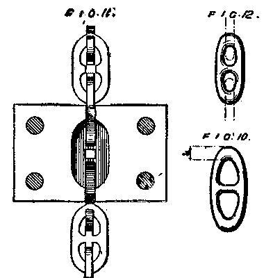
In the manufacture of chains by the aforesaid process of punching there is a practical minimum limit for the dimensions of the punches which cannot be reduced without compromising their efficiency, and consequently the width (and therefore the length) of the link must necessarily bear a certain proportion to the thickness of the web of metal out of which it is formed, since the breadth of the link depends on the length of the cross stay, which is determined by the breadth of the mortises forming the eyes of the link. The present modification enables these dimensions to be reduced without reducing the dimensions, and consequently the efficiency, of the punches which form the eyes of the link. The modification applies to what I have designated the fifth operation of the above described process; and it consists in punching out the middle of the cross stay (so as to leave only two short stumps jutting inward from the side members of the link), this operation serving to interrupt the continuity of the core, which was the object of the fifth operation. For this purpose I substitute for the pair of punches illustrated in Figs. 5a and 5c a single punch, which removes that part of the "core" of the cruciform bar which is situated at the middle of the strut. This tool is represented in Fig. 11, and the effect of its operation is shown in Fig. 12. The subsequent operations, herein designated the sixth, seventh, eighth, and ninth operations, are performed as hereinbefore described; but the tenth operation has the effect of closing together the two stumps, g g, until they abut together at the middle of the link and together constitute a cross strut or stay, which prevents any further lateral collapse of the link. In the operation of closing up the gap between the stumps, g g, the link is brought to the narrow form shown in Fig. 12, the eyes of the links being only just wide enough to receive the end of the adjacent link enchained therewith without gripping it. This operation is performed by a tool similar to that shown in Figs. 10a and 10b, above referred to.