MACHINE DESIGNING.1
Reading edition
MACHINE DESIGNING.1
By JOHN E. SWEET.
"Carrying coals to Newcastle," the oft quoted comparison, fittingly indicates the position I place myself in when attempting to address members of this Institute on the subject of machine designing.
Philadelphia, the birthplace of the great and nearly all the good work in this, the noblest of all industrial arts, needs no help or praise at my hands, but I hope her sons may be prevailed upon to do in their right way what I shall try to do roughly—that is, formulate some rules or establish principles by which we, who are not endowed with genius, may so gauge our work as to avoid doing that which is truly bad. No great author was ever made by studying grammar, rhetoric, language, history, or by imitating some other author, however great.
Neither has there ever been any great poet or artist produced by training. But there are many writers who are not great authors, many rhymsters who are not poets, and many painters who are not artists; and while training will not make great men of them, it will help them to avoid doing that which is absolutely bad, and so may it not be with machine designing? If there are among you some who have a genius for it, what I shall have to say will do you no good, for genius needs no rules, no laws, no help, no training, and the sooner you let what I have to say pass from your minds, the better. Rules only hamper the man of genius; but for us, who either from choice or necessity work away at machine designing without the gift, cannot some simple ruling facts be determined and rules formulated or principles laid down by which we can determine what is really good, and what bad? One of the most important and one of the first things in the construction of a building is the foundation, and the laws which govern its construction can be stated in a breath, and ought to be understood by every one. Assuming the ground upon which a building is to be built to be of uniform density, the width of the foundation should be in proportion to the load, the foundation should taper equally on each side, and the center of the foundation should be under the center of pressure. In other words, it is as fatal to success to have too much foundation under the light load as it is too little under a heavy one.
Cannot we analyze causes and effects, cost and requirements, so as to formulate some simple laws similar to the above by which we shall be able to determine what is a good and what a bad arrangement of machinery, foundation, framing or supports? A vast amount of work is expended to make machines true, and the machines, or a large majority of them, are expected to produce true work of some kind in turn. Then, if this be admitted, cannot the following law be established, that every machine should be so designed and constructed that when once made true it will so remain, regardless of wear and all external influences to which it is liable to be subjected? One tool maker says that it is right, and another that it cannot be done. No matter whether it can or cannot, is it not the thing wanted, and if so, is it not an object worth striving for? One tool maker says that all machine tools, engines, and machinery should set on solid stone foundations. Should they?
They do not always, for in substantial Philadelphia some machine tools used by machine builders stand upon second floors, or, perhaps, higher up. And of these machine tools none, or few at least, except those mounted upon a single pedestal, are free from detrimental torsion where the floor upon which they rest is distorted by unequal loading. But, to first consider those of such magnitude as to render it absolutely necessary to erect them—not rest them—on masonry, is due consideration always taken to arrange an unequal foundation to support the unequal loads?—and they cannot be expected to remain true if not. When one has the good fortune to have a machine to design of such extent that the masonry becomes the main part of it, what part of the glory does he give to the mason? Is the masonry part of it always satisfactory, and is not this resorting to the mason for a frame rather than a support adopted on smaller machines than is necessary? Is it necessary even in a planing machine of forty feet length of bed and a thirty foot table? Could not the bed be cast in three pieces, the center a rectangular box, 5 or 6 or 7 feet square, 20 feet long, with internal end flanges, ways planed on its upper surface, and ends squared off, a monster, perhaps, but if our civil engineers wanted such a casting for a bridge, they'd get it. Add to this central section two bevel pieces of half the length, and set the whole down through the floor where your masonry would have been and rest the whole on two cross walls, and you would have a structure that if once made true would remain so regardless of external influences. Cost? Yes; and so do Frodsham watches—more than "Waterbury."
It may be claimed, in fact, I have seen lathes resting on six and eight feet, engines on ten, and a planing machine on a dozen. Do they remain true? Sometimes they do, and many times they do not. Is the principle right? Not when it can be avoided; and when it cannot be avoided, the true principle of foundation building should be employed.... A strange example of depending on the stone foundation for not simply support, but to resist strain, may be found in the machines used for beveling the edges of boiler plate. Not so particularly strange that the first one might have, like Topsy, "growed," but strange because each builder copies the original. You will remember it, a complete machine set upon a stone foundation, to straighten and hold a plate, and another complete machine set down by the side of it and bolted to the same stone to plane off the edge; a lot of wasted material and a lot of wasted genius, it always seems to me. Going around Robin Hood's barn is the old comparison. Why not hook the tool carriage on the side of the clamping structure, and thus dispense with one of the frames altogether?
Many of the modern builders of what Chordal calls the hyphen Corliss engine claim to have made a great advance by putting a post under the center of the frame, but whether in acknowledgment that the frame would be likely to go down or the stonework come up I could never make out. What I should fear would be that the stone would come up and take the frame with it. Every brick mason knows better than to bed mortar under the center of a window sill; and this putting a prop under the center of an engine girder seems a parallel case. They say Mr. Corliss would have done the same thing if he had thought of it. I do not believe it. If Mr. Corliss had found his frames too weak, he would soon have found a way to make them stronger.
John Richards, once a resident of this city, and likely the best designer of wood-working machinery this country, if not the world, ever saw, pointed out in some of his letters the true form for constructing machine framing, and in a way that it had never been forced on my mind before. As dozens, yes, hundreds, of new designs have been brought out by machine tool makers and engine builders since John Richards made a convert of me, without any one else, so far as I know, having applied the principle in its broadest sense, I hope to present the case to you in a material form, in the hope that it may be more thoroughly appreciated.
The usual form of lathe and planer beds or frames is two side plates and a lot of cross girts; their duty is to guide the carriages or tables in straight lines and carry loads resisting bending and torsional strains. If a designer desires to make his lathe frame stronger than the other fellows, he thinks, if he thinks at all, that he will put in more iron, rather than, as he ought to think, How shall I distribute the iron so it will do the most good?
In illustration of this peculiar way of doing things, which is not wholly confined to machine designers, I should like to relate a story, and as I had to carry the large end of the joke, it may do for me to tell it.
While occupying a prominent position, and yet compelled to carry my dinner, my wife thought the common dinner pail, with which you are probably familiar (by sight, of course), was not quite the thing for a professor (even by brevet) to be seen carrying through the streets. So she interviewed the tinsmith to see if he could not get up something a little more tony than the regulation fifty-cent sort. Oh, yes; he could do that very nicely. How much would the best one he could make cost? Well, if she could stand the racket, he could make one worth a dollar. She thought she could, and the pail was ordered, made, and delivered with pride. Perhaps you can guess the result. A facsimile of the original, only twice the size.
Now, this is a very fair illustration of the fallacy of making things stronger by simply adding iron. To illustrate what I think a much better way, I have had made these crude models (see Fig. 1), for the full force of which, as I said before, I am indebted to John Richards; and I would here add that the mechanic who has never learned anything from John Richards is either a very good or very poor one, or has never read what John Richards has written or heard what he has had to say.
Three models, as shown in Fig. 1, were exhibited; all were of the same general dimensions and containing the same amount of material. The one made on the box principle, c, proved to be fifty per cent. stiffer in a vertical direction than either a or b, from twenty to fifty times stiffer sidewise, and thirteen times more rigid against torsion than either of the others.
However strong a frame may be, its own weight and the weight of the work upon it tends to spring it unless evenly distributed, and to twist it unless evenly proportioned. For all small machines the single post obviates all trouble, but for machine tools of from twice to a half dozen times their own length the single post is not available. Four legs are used for machines up to ten feet or so, and above that legs various and then solid masonry. If the four legs were always set upon solid masonry, and leveled perfectly when set, no question could be raised against the usual arrangement, unless it be this: Ought they not to be set nearly one-fourth the way from the end of the bed? or to put it in another form: Will not the bed of an iron planing machine twelve feet in length be equally as well supported by four legs if each pair is set three feet from the ends—that is, six feet apart—as by six legs, two pairs at the ends and one in the center, and the pairs six feet apart? there being six feet of unsupported bed in either case, with this advantage in favor of the four over the six, settling of the foundation would not bend the bed.
It is not likely that one-half of the four-legged machine tools used in this country are resting upon stable foundations, nor that they ever will be; and while this is a fact, it must also remain a fact that they should be built so as to do their best on an unstable one. Any one of the thousand iron planing machines of the country, if put in good condition and set upon the ordinary wood floors, may be made to plane work winding in either direction by shifting a moving load of a few hundred pounds on the floor from one corner of the machine to the other, and the ways of the ordinary turning lathe may be more easily distorted still. Machine tool builders do not believe this, simply because they have not tried it. That is, I suppose this must be so, for the proof is so positive, and the remedy so simple, that it does not seem possible they can know the fact and overlook it. The remedy in the case of the planer is to rest the structure on the two housings at the rear end and on a pair of legs about one-fourth of the way back from the front, pivoted to the bed on a single bolt as near the top as possible.
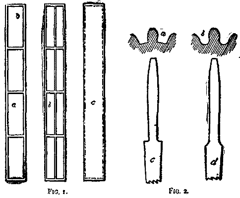
a, b, c Fig. 1, Mr. Sweet, which represented three forms of lathe and planer construction. The box form, c, proved to be fifty per cent. stronger in its vertical direction than either a or b, fifty times stronger sideways than a and twenty times stronger than b, and more than thirteen times stronger than either when subject to torsional strain.
a, Fig. 2, represents an ordinary pinion tooth, and b shows one of the same size strengthened by cutting put metal at the root; c and d were models showing the same width of teeth extended to six times the length, showing what would be their character if considered as springs.
A similar arrangement applies to the lathe and machine tools of that character—that is, machines of considerable length in proportion to their width, and with beds made sufficiently strong within themselves to resist all bending and torsional strains, fill the requirements so far as all except wear is concerned. That is, if the frames are once made true, they will remain so, regardless of all external influences that can be reasonably anticipated.
Among wood-working machines there are many that cannot be built on the single rectangular box plan—rested on three points of support. Fortunately, the requirements are not such as demand absolute straight and flat work, because in part from the fact that the material dealt with will not remain straight and flat even if once made so, and in the design of wood-working machinery it is of more importance to so design that one section or element shall remain true within itself, than that the various elements should remain true with one another.
The lathe, the planing machine, the drilling machine, and many others of the now standard machine tools will never be superseded, and will for a long time to come remain subjects of alteration and attempted improvement in every detail. The head stock of a lathe—the back gear in particular—is about as hard a thing to improve as the link motion of a locomotive. Some arrangement by which a single motion would change from fast to slow, and a substitute for the flanges on the pulleys, which are intended to keep the belt out of the gear, but never do, might be improvements. If the flanges were cast on the head stock itself, and stand still, rather than on the pulley, where they keep turning, the belt would keep out from between the gear for a certainty. One motion should fasten a foot stock, and as secure as it is possible to secure it, and a single motion free it so it could be moved from end to end of the bed. The reason any lathe takes more than a single motion is because of elasticity in the parts, imperfection in the planing, and from another cause, infinitely greater than the others, the swinging of the hold-down bolts.
Should not the propelling powers of a lathe slide be as near the point of greatest resistance as possible, as is the case in a Sellers lathe, and the guiding ways as close to the greatest resistance and propelling power as possible, and all other necessary guiding surfaces made to run as free as possible?
A common expression to be found among the description of new lathes is the one that says "the carriage has a long bearing on the ways." Long is a relative word, and the only place I have seen any long slides among the lathes in the market is in the advertisements. But if any one has the courage to make a long one, they will need something besides material to make a success of it. It needs only that the guiding side that should be long, and that must be as rigid as possible—nothing short of casting the apron in the same piece will be strong enough, because with a long, elastic guide heavy work will spring it down and wear it away at the center, and then with light work it will ride at the ends, with a chattering cut as a consequence.
An almost endless and likely profitless discussion has been indulged in as to the proper way to guide a slide rest, and different opinions exist. It is a question that, so far as principle is concerned, there ought to be some way to settle which should not only govern the question in regard to the slide rest of a lathe, but all slides that work against a torsional resistance, as it may be called—that is, a resistance that does not directly oppose the propelling power. In other words, in a lathe the cutting point of the tool is not in line with the lead screw or rack, and a twisting strain has to be resisted by the slides, whereas in an upright drill the sliding sleeve is directly over and in line with the drill, and subject to no side strain.
Does not the foregoing statement that "the propelling power should be as near the resistance as possible, and the guide be as near in line with the two as possible," embody the true principle? Neither of the two methods in common use meets this requirement to its fullest extent. The two-V New England plan seems like sending two men to do what one can do much better alone; and the inconsistency of guiding by the back edge of a flat bed is prominently shown by considering what the result would be if carried to an extreme. If a slide such as is used on a twenty inch lathe were placed upon a bed or shears twenty feet wide, it would work badly, and that which is bad when carried to an extreme cannot well be less than half bad when carried half way.
The ease with which a cast iron bar can be sprung is many times overlooked. There is another peculiarity about cast iron, and likely other metals, which an exaggerated example renders more apparent than can be done by direct statement. Cast iron, when subject to a bending strain, acts like a stiff spring, but when subject to compression it dents like a plastic substance. What I mean is this: If some plastic substance, say a thick coating of mud in the street, be leveled off true, and a board be laid upon it, it will fit, but if two heavy weights be placed on the ends, the center will be thrown up in the air far away from the mud; so, too, will the same thing occur if a perfectly straight bar of cast iron be placed on a perfectly straight planer bed—the two will fit; but when the ends of the bar are bolted down, the center of the bar will be up to a surprising degree. And so with sliding surfaces when working on oil. If to any extent elastic, they will, when unequally loaded, settle through the oil where the load exists and spring away where it is not.
The tool post or tool holder that permits of a tool being raised or lowered and turned around after the tool is set, without any sacrifice of absolute stability, will be better than one in which either one of these features is sacrificed. Handiness becomes the more desirable as the machines are smaller, but handiness is not to be despised even in a large machine, except where solidity is sacrificed to obtain it.
The weak point in nearly all (and so nearly all that I feel pretty safe in saying all) small planing machines is their absolute weakness as regards their ability to resist torsional strain in the bed, and both torsional and bending strain in the table. Is it an uncommon thing to see the ways of a planer that has run any length of time cut? In fact, is it not a pretty difficult thing to find one that is not cut, and is this because they are overloaded? Not at all. Figure up at even fifty pounds to the square inch of wearing surface what any planer ought to carry, and you will find that it is not from overloading. Twist the bed upon the floor (and any of them will twist as easy as two basswood boards), and your table will rest the hardest on two corners. Strap, or bolt, or wedge a casting upon the table, or tighten up a piece between a pair of centers eight or ten inches above the table, and bend the table to an extent only equal to the thickness of the film of oil between the surface of the ways, and the large wearing surface is reduced to two wearing points. In designing it should always be kept in mind, or, in fact, it is found many times to be the correct thing to do, to consider the piece as a stiff spring, and the stiffer the better. The tooth of a gear wheel is a cast iron spring, and if only treated as would be a spring, many less would be broken. A point in evidence:
The pinions in a train of rolls, which compel the two or more rolls to travel in unison, are necessarily about as small at the pitch line as the rolls themselves; they are subject to considerable strain and a terrible hammering by back lash, and break discouragingly frequent, or do when made of cast iron, if not of very coarse pitch, that is, with very few teeth—eleven or twelve sometimes.
In a certain case it became desirable to increase the number of teeth, when it was found that the breakages occurred about as the square root of their number. When the form was changed by cutting out at the root in this form (Fig. 2), the breakage ceased.
a, Fig. 2, shows an ordinary gear tooth, and b the form as changed; c and d show the two forms of the same width, but increased to six times the length. If the two are considered as springs, it will be seen that d is much less likely to be broken by a blow or strain.
The remedy for the flimsy bed is the box section; the remedy for the flimsy planer table is the deep box section, and with this advantage, that the upper edge can be made to shelve over above the reversing dogs to the full width between the housings.
The parabolic form of housing is elegant in appearance, but theoretically right only when of uniform cross section. In some of the counterfeit sort the designers seem to have seen the original Sellers, remembering the form just well enough to have got the curve wrong end up, and knowing nothing of the principle, have succeeded in building a housing that is absolutely weak and absolutely ugly, with just enough of the original left to show from where it was stolen. If the housing is constructed on the brace plan, should not the braces be straight, as in the old Bement, and the center line of strain pass through the center line of the brace? If the housing is to take the form of a curve, the section should be practically uniform, and the curve drawn by an artist. Many times housings are quite rigid enough in the direction of the travel of the table, but weak against side pressure. The hollow box section, with secure attachment to the bed and a deep cross beam at the top, are the remedies.
Raising and lowering cross heads, large and small, by two screws is a slow and laborious job, and slow when done by power. Counterweights just balancing the cross head, with metal straps rather than chains or ropes, large wheels with small anti-friction journals, and the cross head guarded by one post only, changes a slow to a quick arrangement, and a task to a comfort. Housings of the hollow box section furnish an excellent place for the counterweights.
The moving head, which is not expected to move while under pressure, seems to have settled into one form, and when hooked over a square ledge at the top, a pretty satisfactory form, too. But in other machines built in the form of planing machines, in which the head is traversed while cutting, as is the case with the profiling machine, the planer head form is not right. Both the propelling screw, or whatever gives the side motion, should be as low down as possible, as should also be the guide.
There is a principle underlying the Sellers method of driving a planer table that may be utilized in many ways. The endurance goes far beyond any man's original expectations, and the explanation, very likely, lies in the fact that the point of contact is always changing. To apply the same principle to a common worm gear it is only necessary to use a worm in a plain spur gear, with the teeth cut at an angle the wrong way, and set the worm shaft at an angle double the amount, rather than at 90°. Such a worm gear will, I fancy, outwear a dozen of the scientific sort. It would likely be found a convenience to have the head of a planing machine traverse by a handle or crank attached to itself, so it could be operated like the slide rest of a lathe, rather than as is now the case from the end of the cross head. The principle should be to have things convenient, even at an additional cost. Anything more than a single motion to lock the cross head to the housing or stanchions should not be countenanced in small planers at least. Many of the inferior machines show marked improvements over the better sorts, so far as handiness goes, while there is nothing to hinder the handy from being good and the good handy.
When we consider that since the post-drilling machine first made its appearance, there have been added Blasdell's quick return, the automatic feed, belt-driven spindles, back gears placed where they ought to be, with many minor improvements, it is not safe to assume that the end has been reached; and when we consider that as a piece of machine designing, considered in an artistic sense entirely, the Bement post drill is the finest the world ever saw (the Porter-Allen engine not excepted, which is saying a good deal), is it not strange that of all mechanical designs none other has taken on such outrageous forms as this?
One thing that would seem to be desirable, and that ordinary skill might devise, is some sort of snap clutch by which the main spindle could be stopped instantly by touching a trigger with the foot; many drills and accidents would be saved thereby. Of the many special devices I have seen for use on a drilling machine, one used by Mr. Lipe might be made of universal use. It is in the form of a bracket or knee adjustably attached to the post, which has in its upper surface a V into which round pieces of almost any size can be fastened, so that the drill will pass through it diametrically. It is not only useful in making holes through round bars, but straight through bosses and collars as well.
The radial drill has got so it points its nose in all directions but skyward, but whether in its best form is not certain. The handle of the belt shipper, in none that I have seen, follows around within reach of the drill as conveniently as one would like.
As the one suggestion I have to make in regard to the shaping machine best illustrates the subject of maintaining true wearing surfaces, I will leave it until I reach that part of my paper.
(To be continued.)
[1]
A lecture delivered before the Franklin Institute, Philadelphia, Monday, Jan. 30, 1888. From the journal of the Institute.