COMPRESSED OIL GAS FOR LIGHTING CARS, STEAMBOATS, AND BUOYS.
Reading edition
We give in the accompanying figures the arrangement of the different apparatus necessary for the manufacture and compression of illuminating gas on the system of Mr. Pintsch, as well as the arrangements adopted by the inventor for the lighting of railway cars and buoys. This system has been adopted to some extent in both Germany and England, and is also being introduced into France.
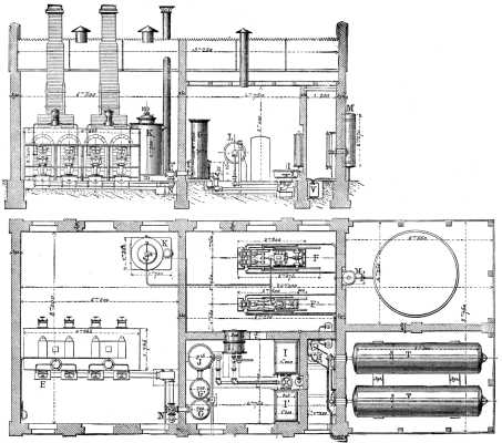
WORKS FOR THE MANUFACTURE OF OIL GAS.--ELEVATION AND PLAN.
The Pintsch gas is prepared by the distillation of heavy oils in a furnace composed of two superposed retorts. The oil to be volatilized is contained in a vertical reservoir B, which carries a bent pipe that enters the upper retort, A. The flow of the oil is regulated in this conduit by means of a micrometer screw which permits of varying the supply according to the temperature of the retorts. In order to facilitate the vaporization, the flow of oil starts from a cast-iron trough, C, and from thence spreads in a thin and uniform layer in the retort. The residua of distillation remain almost entirely in the reservoir, O, from whence they are easily removed. The vapor from the oil which is disengaged in the vessel, A, goes to the lower retort, D, in which the transformation of the matter is thoroughly completed. On leaving the latter, the gas enters the drum, E, at the lower part of the furnace. To prevent the choking up of the pipe, R, the latter is provided with a joint permitting of dilatation. The gas on leaving E goes to the condenser, G G, where it is freed from its tar. The latter flows out, and the gas proceeds to the washer, J, and the purifiers, I and I, to be purified. The amount of production is registered by the meter, L.
When the gas is to be utilized for lighting railway cars or buoys, it is compressed in the accumulators, T, which are large cylindrical reservoirs of riveted or welded iron plate.
Compression is effected by means of a pump, F or F', which sucks the gas into a desiccating cylinder, M, connected with the gasometer of the works The pump, F, which is used when the production is larger than usual, has two compressing cylinders of different diameters, one measuring 170 millimeters and the other 100. The piston has a stroke of 320 millimeters. The two compressing cylinders are double acting, and communicate with each other by valves so arranged as to prevent injurious spaces. The gas drawn from the gasometer is first compressed in the larger cylinder to a pressure of about 4 atmospheres; then it passes into the second cylinder, whence it is forced into the accumulators under a pressure varying from 10 to 12 atmospheres.
For a not very large production, the small pump suffices. This has a single compressing cylinder connected directly with the piston rod, upon which acts the steam coming from the boiler, K. This pump compresses the gas to a pressure of 10 atmospheres, and is capable of storing seven cubic meters of it per hour.
The carburets of hydrogen which separate in a liquid state through the effect of the compression of the gas are retained in a cylindrical receptacle, V, which is located between the pump and the accumulators, T.
Besides the necessary safety apparatus, there is disposed in front of the condensers a special valve, N, which allows the gas to escape into the air if the retorts or the purifying apparatus get choked up.
When the oil gas is not compressed it possesses an illuminating power four times greater than that obtained from coal gas; and, while the latter loses the greater part of its luminous power by compression, the former loses only an eighth. It is this property that renders the oil gas eminently fitted for lighting cars, and it is for this reason that several large European railway companies have adopted it.
APPLICATION TO CARS.
We show in the accompanying engravings the mode of installation that the inventor has finally adopted for railway purposes. Each car is furnished, perpendicularly to its length, with a reservoir, a, containing the supply of gas under a pressure of 6 or 7 atmospheres. The gas is introduced into this reservoir by means of a valve, which is put in communication with the mouths of supply pipes placed along a platform. The pipes are provided with a stopcock and their mouths are closed by a cap. To fill the car reservoir it is only necessary to connect the mouths of the supply pipes with the valves of the cars by means of rubber tubing--an operation which takes about one minute for each car.
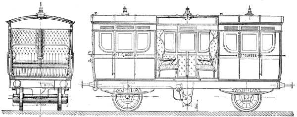
LIGHTING OF RAIWAY CARS
When it is necessary to supply cars at certain points where there are no gas works, there is attached to the train a special car on which are placed two or three accumulators, which thus transport a supply of the compressed gas to distances that are often very far removed from the source of supply.
The reservoir of each car, containing a certain supply of gas, communicates with a regulator, b, the importance of which we scarcely need point out. This apparatus consists: (1) of a cast-iron cup, A, closed at the top by a membrane, B, which is impervious to gas; (2) of a rod, C, connected at one end with the membrane, and at the other with a lever, D; (3) of a regulating valve resting on the lever, and of a spring, E, which renders the internal mechanism independent of the motions of the car. The lever, acting for the opening and closing of the valve, serves to admit gas into the regulator through the aperture, F. This latter is so calculated as to allow the passage of a quantity of gas corresponding to a pressure of 16 millimeters. As soon as such a pressure is reached in the regulator, the membrane rises and acts on the lever, and the latter closes the valve. When the pressure diminishes, as a consequence of the consumption of gas, the spring, E, carries the lever to its initial position and another admission of gas takes place. Communication between the regulator and the lamps is effected by means of a pipe, z, of 7 millimeters diameter (provided with a cock, d, which permits of extinguishing all the lamps at once, and by special branches for each lamp. The lamps used differ little in external form from those at present employed. The body is of cast-iron; the cover, funnel, and chimney are of tin; and the burner is of steatite. The products of combustion are led outside through a flattened chimney, t, resting at o on the center of the reflector. The air enters through the cover of the lamp and reaches the interior through a series of apertures in the circumference of the cast-iron bell which supports the reflector. There is no communication whatever between the interior of the lamp and the interior of the car, and thus there is no danger of passengers being annoyed by the odor of gas. By means of a peculiar apparatus, f, the flame may be reduced to a minimum without being extinguished. This arrangement is at the disposition of the conductor or within reach of the passengers. For facilitating cleaning, the lamps are arranged so as to turn on a hinge-joint, m; so that, on removing the reflector, o, it is only necessary to raise the arm that carries the burner, r in order to clean the base, s, without any difficulty.
On several railways both the palace and postals cars are also heated by compressed oil gas; and lately an application has been made of the gas for supplying the headlights of locomotives (see figure), and for the signals placed at the rear of trains. But one of the most interesting applications of oil is that of
LIGHTING BUOYS,
in which case it is compressed into large reservoirs placed on a boat. The buoys employed are generally of from 90 to 285 cubic feet capacity, affording a lighting for from 35 to 100 days.
To the upper part of the buoy there is affixed a firmly supported tube carrying at its extremity the lantern, c. The gas compressed to 6 or 7 atmospheres in the body of the buoy passes, before reaching the burner, into a regulator analogous to the one installed on railway cars, but modified in such a way as to operate with regularity whatever be the inclination of the buoy. In the section showing the details of the lantern on a large scale the direction taken by the air is indicated by arrows, as is also the direction taken by the products of combustion. These latter escape at m, through apertures in the cap of the apparatus.
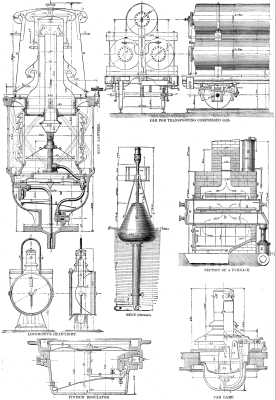
COMPRESSED OIL GAS FOR LIGHTING CARS STEAMBOTS, AND BUOYS.
The regulator, B, in the interior of the lantern, brings to a uniform pressure the inclosed gas, whose pressure continues diminishing as a consequence of the consumption. The lantern is protected against wind and waves by very thick convex glasses set into metallic cross-bars, c. The flame is located in the focus of a Fresnel lens, b, consisting of superposed prismatic rings, and adjusted at its lower part with a circle, d, while a conical ring, e makes a joint at its other extremity. This ring is held by the top piece of the lantern through the intermedium of six spiral springs, c' c''. Under the focus of the flame there is placed a conical reflector of German silver, t.
The buoy is filled through an aperture, k, in the side of the upper tube. This aperture is provided with a valve which allows of the buoy being charged by connecting it with the accumulators located on a boat built especially for this service. As soon as the gas reaches 6 or 7 atmospheres the cocks of the buoy and reservoir are closed, and the connecting tube is removed. The consumption of gas in the lantern is. 1,230 cubic inches per hour. This being known it is very easy to calculate from the capacity of the buoy how often it is necessary to charge it.
A large number of buoys on the Pintsch system are already in use.
The oil gas is likewise applicable to the illumination of lighthouses, and among those that are now being lighted in that way we may cite the one in the port of Pillau, near Königsberg. Several large steamers are likewise being lighted on this plan. In such an application of oil gas the management of the apparatus is very easy, and the permanence of the illuminating power of the gas gives every facility for the lighting of the boat, whatever be the duration of the trip.
Although Mr. Pintsch's process of manufacture has been but recently introduced into France, it has received a number of applications that permits us to foresee the future that is in store for it. The Railway Company of the West has contracted for the lighting of 250 first-class cars that run within the precincts of the city; the State Railways have 56 cars lighted in this way running between Nantes and Bordeaux and between Saintes and Limoges; and the Line of the East has just applied the system to 80 of its cars.