THE CALORIMETER.
Reading edition
In describing this apparatus, for the sake of clearness, the calorimetric features will be considered before the appliances for the determination of the respiratory products.
FUNDAMENTAL PRINCIPLES OF THE APPARATUS.
The measurements of heat eliminated by man, as made by this apparatus, are based upon the fact that the subject is inclosed in a heat-proof chamber through which a current of cold water is constantly passing. The amount of water, the flow of which, for the sake of accuracy, is kept at a constant rate, is carefully weighed. The temperatures of the water entering and leaving the chamber are accurately recorded at frequent intervals. The walls of the chamber are held adiabatic, thus preventing a gain or loss of heat by arbitrarily heating or cooling the outer metal walls, and the withdrawal of heat by the water-current is so controlled, by varying the temperature of the ingoing water, that the heat brought away from the calorimeter is exactly equal in amount to the heat eliminated by radiation and conduction by the subject, thus maintaining a constant temperature inside of the chamber. The latent heat of the water vaporized is determined by measuring directly the water vapor in the ventilating air-current.
In the construction of the new calorimeters a further and fundamental change in construction has been made in that all the thermal junctions, heating wires, and cooling pipes have been attached directly to the zinc wall of the calorimeter, leaving the outer insulating panels free from incumbrances, so that they can be removed readily and practically all parts inspected whenever desired without necessitating complete dismantling of the apparatus. This arrangement is possible except in those instances where connections pass clear through from the interior of the chamber to the outside, namely, the food-aperture, air-pipes, water-pipes, electrical connections, and tubes for connections with pneumograph and stethoscope; but the apparatus is so arranged as to have all of these openings in one part of the calorimeter. It is possible, therefore, to remove all of the outer sections of the calorimeter with the exception of panels on the east side.
This fundamental change in construction has proven highly advantageous. It does away with the necessity of rolling the calorimeter out of its protecting insulating house and minimizes the delay and expense incidental to repairs or modifications. As the calorimeter is now constructed, it is possible to get at all parts of it from the outside, with the exception of one small fixed panel through which the above connections are passed. This panel, however, is made as narrow as possible, so that practically all changes can be made by taking out the adjacent panels.
THE CALORIMETER CHAMBER.
Fig. 7.—Horizontal cross-section of chair calorimeter, showing cross-section of copper wall at A, zinc wall at B, hair-felt at E, and asbestos outer wall at F; also cross-section of all upright channels in the steel construction. At the right is the location of the ingoing and outgoing water and the thermometers. At C is shown the food aperture, and D is a gasket separating the two parts. The ingoing and outcoming air-pipes are shown at the right inside the copper wall. The telephone is shown at the left, and in the center of the drawing is the chair with its foot-rest, G. In dotted line is shown the opening where the man enters.
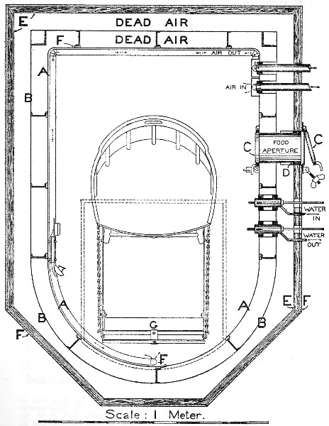
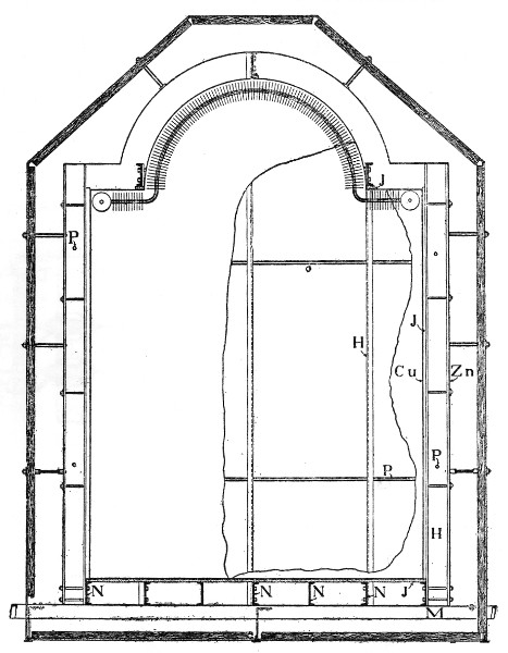
Fig. 8.—Vertical cross-section of chair calorimeter, showing part of rear of calorimeter and structural-steel frame. N, cross-section of bottom horizontal channel supporting asbestos floor J; H, H, upright channels (at the right is a side upright channel and to the left of this is an upright rear channel); M horizontal 8-inch channel supporting calorimeter; Zn, zinc wall; Cu, copper wall; J, insulating asbestos.
The respiration chamber used in Middletown, Connecticut, was designed to permit of the greatest latitude in the nature of the experiments to be made with it. As a result, it was found at the end of a number of years of experimenting that this particular size of chamber was somewhat too small for the most satisfactory experiments during muscular work and, on the other hand, somewhat too large for the best results during so-called rest experiments. In the earlier experiments, where no attempt was made to determine the consumption of oxygen, these disadvantages were not so apparent, as carbon dioxide could be determined with very great accuracy; but with the attempts to measure the oxygen it was found that the large volume of residual air inside the chamber, amounting to some 4,500 liters, made possible very considerable errors in this determination, for, obviously, the subject could draw upon the oxygen residual in the air of the chamber, nearly 1,000 liters, as well as upon the oxygen furnished from outside sources. The result was that a very careful analysis of the residual air must be made frequently in order to insure that the increase or decrease in the amount of oxygen residual in the air of the chamber was known accurately at the end of each period. Analysis of this large volume of air could be made with considerable accuracy, but in order to calculate the exact total of oxygen residual in the air it was necessary to know the total volume of air inside the chamber under standard conditions. This necessitated, therefore, a careful measurement of temperature and pressure, and while the barometric pressure could be measured with a high degree of accuracy, it was found to be very difficult to determine exactly the average temperature of so large a mass of air. The difficulties attending this measurement and experiments upon this point are discussed in detail elsewhere.[5] Consequently, as a result of this experience, in planning the calorimeters for the Nutrition Laboratory it was decided to design them for special types of experiments. The first calorimeter to be constructed was one which would have general use in experiments during rest and, indeed, during experiments with the subject sitting quietly in the chair.
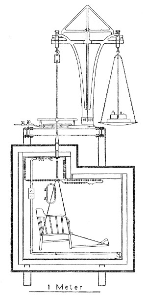
Fig. 9.—Vertical cross-section of chair calorimeter from front to back, showing structural steel supporting the calorimeter and the large balance above for weighing the subject inside the calorimeter. The chair, method of suspension, and apparatus for raising and lowering are shown. Part of the heat-absorbers is shown, and their general direction. The ingoing and outgoing air-pipes and direction of ventilation are also indicated. The positions of the food-aperture and wire mat and asbestos support are seen. Surrounding the calorimeter are the asbestos outside and hair-felt lining.
It may well be asked why the first calorimeter was not constructed of such a type as to permit the subject assuming a position on a couch or sofa, such as is used by Zuntz and his collaborators in their research on the respiratory exchange, or the position of complete muscular rest introduced by Johansson and his associates. While the body positions maintained by Zuntz and Johansson may be the best positions for experiments of short duration, it was found, as a result of a large number of experiments, that subjects could be more comfortable and quiet for periods of from 6 to 8 hours by sitting, somewhat inclined, in a comfortable arm-chair, provided with a foot-rest. With this in mind the first calorimeter was constructed so as to hold an arm-chair with a foot-rest so adjusted that the air-space between the body of the subject and the walls of the chamber could be cut down to the minimum and thus increase the accuracy of the determination of oxygen. That the volume has been very materially reduced may be seen from the fact that the total volume of the first calorimeter to be described is less than 1,400 liters, or about one-third that of the Middletown apparatus.
GENERAL CONSTRUCTION.
A horizontal cross-section of the apparatus is shown in fig. 7, and a vertical cross-section facing the front is given in fig. 8. Other details of structural steel are seen in fig. 9.
In constructing the new chambers, the earlier wood construction, with its tendency to warp and its general non-rigidity, was avoided by the use of structural steel, and hence in this calorimeter no use whatever is made of wood other than the wood of the chair.
To avoid temperature fluctuations due to possible local stratification of the air in the laboratory, the calorimeter is constructed so as to be practically suspended in the air, there being a large air-space of some 76 centimeters between the lowest point of the calorimeter and the floor, and the top of the calorimeter is some 212 centimeters below the ceiling of the room. Four upright structural-steel channels (4-inch) were bolted through the floor, so as to secure great rigidity, and were tied together at the top with structural steel. As a solid base for the calorimeter chamber two 3-inch channels were placed parallel to each other 70 centimeters from the floor, joined to these uprights. Upon these two 3-inch channels the calorimeter proper was constructed. The steel used for the most part in the skeleton of the apparatus is standard 2-1/2-inch channel. This steel frame and its support are shown in fig. 10, before any of the copper lining was put into position. The main 4-inch channels upon which the calorimeter is supported, the tie-rods and turn-buckles anchoring the framework to the ceiling, the I-beam construction at the top upon which is subsequently installed the large balance for weighing the man, the series of small channels set on edge upon which the asbestos floor is laid, and the upright row of channel ribs are all clearly shown.
Fig. 10 Photograph of framework of chair calorimeter. In the photograph are shown four upright channels and the channels at the top for supporting the calorimeter. The smaller upright 2-1/2 inch channels and angles are shown inside of this frame. In the lower part of the figure is seen the asbestos board for the bottom of the calorimeter and underneath this a sheet of zinc.
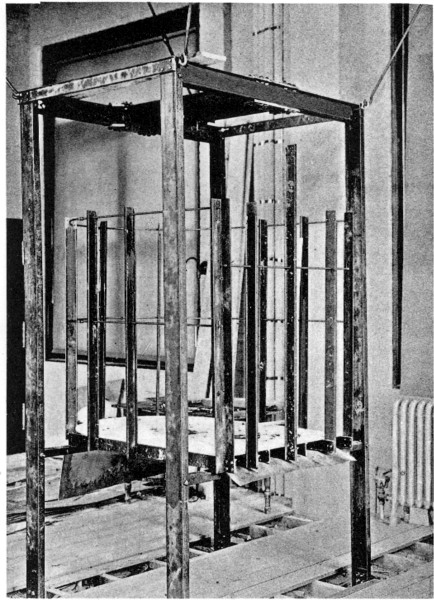
Fig. 11 Photograph of portion of framework and copper shell. The finished copper shell is seen in position with some of the thermal junction thimbles soldered into it. A portion of the food aperture and the four brass ferrules for conducting the water pipes and air pipes are shown. A section of the zinc outside is shown in the lower part of the figure.
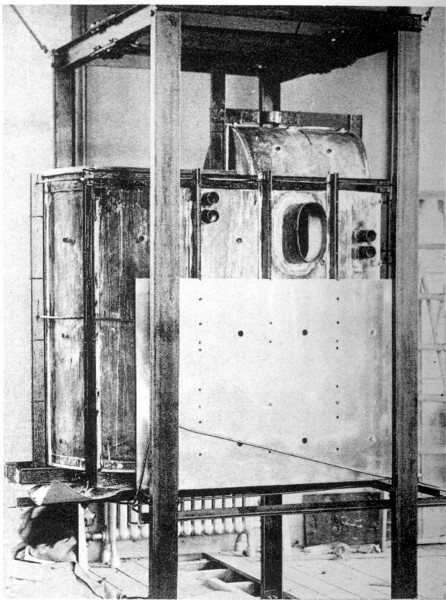
A photograph taken subsequently, showing the inner copper lining in position, is given in fig. 11.
The floor of the chamber is supported by 7 pieces of 2-1/2-inch channel (N, N, N, fig. 8), laid on top and bolted to the two 3-inch channels (M, fig. 8). On top of these is placed a sheet of so-called asbestos lumber (J', fig. 8) 9.5 millimeters thick, cut to fit exactly the bottom of the chamber. Upright 2-1/2-inch channels (H, fig. 8) are bolted to the two outside channels on the bottom and to the ends of three of the long channels between in such a manner as to form the skeleton of the walls. The upper ends of these channels are fastened together by pieces of piping (P, P, P, fig. 8) with lock-nuts on either side, thus holding the whole framework in position.
The I-beams and channels used to tie the four upright channels at the top form a substantial platform upon which is mounted a large balance (fig. 9). This platform is anchored to the ceiling at four points by tie rods and turn-buckles, shown in fig. 4. The whole apparatus, therefore, is extremely rigid and the balance swings freely.
The top of the chamber is somewhat restricted near the edges (fig. 8) and two lengths of 2-1/2-inch channel support the sides of the opening through which the subject enters at the top (fig. 7).
Both the front and back lower channels upon which the bottom rests are extended so as to provide for supports for the outer walls of asbestos wood, which serve to insulate the calorimeter. Between the channels beneath the calorimeter floor and the 3-inch channels is placed a sheet of zinc which forms the outer bottom metallic wall of the chamber.
In order to prevent conduction of heat through the structural steel all contact between the inner copper wall and the steel is avoided by having strips of asbestos lumber placed between the steel and copper. These are shown as J in fig. 8 and fig. 12. A sheet of asbestos lumber beneath the copper bottom likewise serves this purpose and also serves to give a solid foundation for the floor. The supporting channels are placed near enough together to reinforce fully the sheet of asbestos lumber and enable it to support solidly the weight of the man. The extra strain on the floor due to tilting back a chair and thus throwing all the weight on two points was taken into consideration in planning the asbestos and the reinforcement by the steel channels. The whole forms a very satisfactory flooring.
Wall construction and insulation.—The inner wall of the chamber consists of copper, preferably tinned on both sides, thus aiding in soldering, and the tinned inner surface makes the chamber somewhat lighter. Extra large sheets are obtained from the mill, thus reducing to a minimum the number of seams for soldering, and seams are made tight only with difficulty. The copper is of standard gage, the so-called 14-ounce copper, weighing 1.1 pounds per square foot or 5.5 kilograms per square meter. It has a thickness of 0.5 millimeter. The whole interior of the skeleton frame of the structural steel is lined with these sheets; fig. 11 shows the copper shell in position.
For the outer metallic wall, zinc, as the less expensive metal, is used. One sheet of this material perforated with holes for the attachment of bolts and other appliances is shown in position on the outside of the wall in fig. 11. The sheet zinc of the floor is obviously put in position before the channels upon which it rests are laid. The zinc is obtained in standard size, and is the so-called 9-ounce zinc, or 0.7 pound to the square foot, or 3.5 kilograms to the square meter. The sheet has a thickness of 0.5 millimeter.
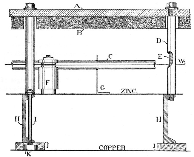
Fig. 12.—Cross-section in detail of walls of calorimeter, showing zinc and copper walls and asbestos outside (A); hair-felt lining (B); cross-section of channel iron (H); brass washer soldered to copper (K); asbestos insulation between channel iron and copper (J); bolt holding the whole together (I); heating wire (W) and insulator holding it (F) shown in air-space between zinc and hair-felt; section of one of the cooling pipes (C) and its brass support (G); threaded rod (E) fastened into H at one end and passing through asbestos wall with a nut on the outside; and iron pipe (D) used as spacer between asbestos and zinc.
In the cross-section, fig. 7, A represents the copper wall and B the zinc wall. Surrounding this zinc wall and providing air insulation is a series of panels constructed of asbestos lumber, very fire-resisting, rigid, and light. The asbestos lumber used for these outer panels is 6.4 millimeters (0.25 inch) thick. To further aid in heat insulation we have glued to the inner face of the different panels a patented material composed of two layers of sheathing-paper inclosing a half-inch of hair-felt. This material is commonly used in the construction of refrigerators. This is shown as E in fig. 7, while the outer asbestos panels are shown as F.
A detail of the construction of the walls, showing in addition the heating and cooling devices, is given in fig. 12, in which the copper is shown held firmly to the upright channel H by means of the bolt I, screwing into a brass or copper disk K soldered to the copper wall. The bolt I serves the purpose of holding the copper to the upright channel and likewise by means of a washer under the head of the screw holds the zinc to the channel. In order to hold the asbestos-lumber panel A with the hair-felt lining B a threaded rod E is screwed into a tapped hole in the outer part of the upright channel H. A small piece of brass or iron tubing, cut to the proper length, is slipped over this rod and the asbestos lumber held in position by a hexagonal nut with washer on the threaded rod E. In this manner great rigidity of construction is secured, and we have two air-spaces corresponding to the dead air-spaces indicated in fig. 7, the first between the copper and zinc and the second between the zinc and hair-felt.
PREVENTION OF RADIATION.
As can be seen from these drawings the whole construction of the apparatus is more or less of the refrigerator type, i. e., there is little opportunity for radiation or conduction of heat. Such a construction could be multiplied a number of times, giving a greater number of insulating walls, and perhaps reducing radiation to the minimum, but for extreme accuracy in calorimetric investigations it is necessary to insure the absence of radiation, and hence we have retained the ingenious device of Rosa, by which an attempt is made arbitrarily to alter the temperature of the zinc wall so that it always follows any fluctuations in the temperature of the copper wall. To this end it is necessary to know first that there is a temperature difference between zinc and copper and, second, to have some method for controlling the temperature of the zinc. Leaving for a moment the question of measuring the temperature differences between zinc and copper, we can consider here the methods for controlling the temperature of the zinc wall.
If it is found necessary to warm the zinc wall, a current of electricity is passed through the resistance wire W, fig. 12. This wire is maintained approximately in the middle of the air-space between the zinc wall and hair-felt by winding it around an ordinary porcelain insulator F, held in position by a threaded rod screwed into a brass disk soldered to the zinc wall. A nut on the end of the threaded rod holds the insulator in position. Much difficulty was had in securing a resistance wire that would at the same time furnish reasonably high resistance and would not crystallize or become brittle and would not rust. At present the best results have been obtained by using enameled manganin wire. The wire used is No. 28 American wire-gage and has resistance of approximately 1.54 ohms per foot. The total amount of wire used in any one circuit is equal to a resistance of approximately 92 ohms. This method of warming the air-space leaves very little to be desired. It can be instantaneously applied and can be regulated with the greatest ease and with the greatest degree of refinement.
If, on the other hand, it becomes necessary to cool the air-space next to the zinc and in turn cool the zinc, we must resort to the use of cold water, which is allowed to flow through the pipe C suspended in the air-space between the zinc and hair-felt at approximately the same distance as is the heating wire. The support of these pipes is accomplished by placing them in brass hangers G, soldered to the zinc and provided with an opening in which the pipe rests.
In the early experimenting, it was found impracticable to use piping of very small size, as otherwise stoppage as a result of sediment could easily occur. The pipe found best adapted to the purpose was the so-called standard one-eighth inch brass pipe with an actual internal diameter of 7 millimeters. The opening of a valve allowed cold water to flow through this pipe and the considerable mass of water passing through produced a very noticeable cooling effect. In the attempt to minimize the cooling effect of the mass of water remaining in the pipe, provision was made to allow water to drain out of this pipe a few moments after the valve was closed by a system of check-valves. In building the new apparatus, use was made of the compressed-air service in the laboratory to remove the large mass of cold water in the pipe. As soon as the water-valve was closed and the air-cock opened, the compressed air blew all of the water out of the tube.
Fig. 13.—Detail of drop-eight feed-valve and arrangement of outside cooling circuit. The water enters at A, and the flow is regulated by the needle-valve at left-hand side. Rate of flow can be seen at end of exit tube just above the union. The water flows out at C and compressed air is admitted at B, regulated by the pet-cock.
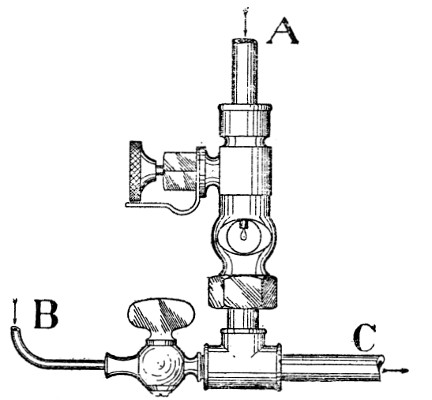
The best results have been obtained, however, with an entirely new principle, namely, a few drops of water are continually allowed to pass into the pipe, together with a steady stream of compressed air. This cold water is forcibly blown through the pipe, thus cooling to an amount regulated by the amount of water admitted. Furthermore, the relatively dry air evaporates some of the water, thereby producing a somewhat greater cooling effect. By adjusting the flow of water through the pipe a continuous cooling effect of mild degree may be obtained. While formerly the air in the space next the zinc wall was either cooled or heated alternately by opening the water-valve or by passing a current through the heating coil, at present it is found much more advantageous to allow a slow flow of air and water through the pipes continuously, thus having the air-space normally somewhat cooler than is desired. The effect of this cooling, therefore, is then counterbalanced by passing an electric current of varying strength through the heating wire. By this manipulation it is unnecessary that the observer manipulate more than one instrument, namely, the rheostat, while formerly he had to manipulate valves, compressed-air cocks, and rheostat. The arrangement for providing for the amount of compressed air and water is shown in fig. 13, in which it is seen that a small drop-sight feed-water valve is attached to the pipe C leading into the dead air-space surrounding the calorimeter chamber. Compressed air enters at B and the amount entering can be regulated by the pet-cock. The amount of water admitted is readily observed by the sight feed-valve. When once adjusted this form of apparatus produces a relatively constant cooling effect and facilitates greatly the manipulation of the calorimetric apparatus as a whole.
THE THERMO-ELECTRIC ELEMENTS.
In order to detect differences in temperature between the copper and zinc walls, some system for measuring temperature differences between these walls is essential. For this purpose we have found nothing that is as practical as the system of iron-German-silver thermo-electric elements originally introduced in this type of calorimeter by E. B. Rosa, of the National Bureau of Standards, formerly professor of physics at Wesleyan University. In these calorimeters the same principle, therefore, has been applied, and it is necessary here only to give the details of such changes in the construction of the elements, their mounting, and their insulation as have been made as a result of experience in constructing these calorimeters. An element consisting of four pairs of junctions is shown in place as T-J in fig. 25.
One ever-present difficulty with the older form of element was the tendency for the German-silver wires to slip out of the slots in which they had been vigorously crowded in the hard maple spool. In thus slipping out of the slots they came in contact with the metal thimble in the zinc wall and thus produced a ground. In constructing the new elements four pairs of iron-German-silver thermal junctions were made on essentially the same plan as that previously described,[6] the only modification being made in the spool. While the ends of the junctions nearest the copper are exposed to the air so as to take up most rapidly the temperature of the copper, it is somewhat difficult to expose the ends of the junctions nearest the zinc and at the same time avoid short-circuiting. The best procedure is to extend the rock maple spool which passes clear through the ferule in the zinc wall and cut a wide slot in the spool so as to expose the junctions to the air nearest the ferule. By so doing the danger to the unprotected ends of the junctions is much less. The two lead-wires of German silver can be carried through the end of the spool and thus allow the insulation to be made much more satisfactorily. In these calorimeters free use of these thermal junctions has been made. In the chair calorimeter there are on the top 16 elements consisting of four junctions each, on the rear 18, on the front 8, and on the bottom 13. The distribution of the elements is made with due reference to the direction in which the heat is most directly radiated and conducted from the surface of the body.
While the original iron-German-silver junctions have been retained in two of these calorimeters for the practical reason that a large number of these elements had been constructed beforehand, we believe it will be more advantageous to use the copper-constantin couple, which has a thermo-electric force of 40 microvolts per degree as against the 25 of the iron-German-silver couple. It is planned to install the copper-constantin junctions in the calorimeters now building.
INTERIOR OF THE CALORIMETER.
Since the experiments to be made with this chamber will rarely exceed 6 to 8 hours, there is no provision made for installing a cot bed or other conveniences which would be necessary for experiments of long duration. Aside from the arm-chair with the foot-rest suspended from the balance, there is practically no furniture inside of the chamber, and a shelf or two, usually attached to the chair, to support bottles for urine and drinking-water bottles, completes the furniture equipment. The construction of the calorimeter is such as to minimize the volume of air surrounding the subject and yet secure sufficient freedom of movement to have him comfortable. A general impression of the arrangement of the pipes, chair, telephone, etc., inside the chamber can be obtained from figs. 7 and 9. The heat-absorber system is attached to rings soldered to the ceiling at different points. The incoming air-pipe is carried to the top of the central dome, while the air is drawn from the calorimeter at a point at the lower front near the position of the feet of the subject. From this point it is carried through a pipe along the floor and up the rear wall of the calorimeter to the exit.
With the perfect heat insulation obtaining, the heat production of the man would soon raise the temperature to an uncomfortable degree were there no provisions for withdrawing it. It is therefore necessary to cool the chamber and, as has been pointed out, the cooling is accomplished by passing a current of cold water through a heat-absorbing apparatus permanently installed in the interior of the chamber. The heat-absorber consists of a continuous copper pipe of 6 millimeters internal diameter and 10 millimeters external diameter. Along this pipe there are soldered a large number of copper disks 5 centimeters in diameter at a distance of 5 millimeters from each other. This increases enormously the area for the absorption of heat. In order to allow the absorber system to be removed, added to, or repaired at any time, it is necessary to insert couplings at several points. This is usually done at corners where the attachment of disks is not practicable. The total length of heat-absorbers is 5.6 meters and a rough calculation shows that the total area of metal for the absorption of heat is 4.7 square meters. The total volume of water in the absorbers is 254 cubic centimeters.
It has been found advantageous to place a simple apparatus to mix the water in the water-cooling circuit at a point just before the water leaves the chamber. This water-mixer consists of a 15-centimeter length of standard 1-inch pipe with a cap at each end. Through each of these caps there is a piece of one-eighth-inch pipe which extends nearly the whole length of the mixer. The water thus passing into one end returns inside the 1-inch pipe and leaves from the other. This simple device insures a thorough mixing.
The air-pipes are of thin brass, 1-inch internal diameter. One of them conducts the air from the ingoing air-pipe up into the top of the central dome or hood immediately above the head of the subject. The air thus enters the chamber through a pipe running longitudinally along the top of the dome. On the upper side of this pipe a number of holes have been drilled so as to have the air-current directed upwards rather than down against the head of the subject. With this arrangement no difficulties are experienced with uncomfortable drafts and although the air enters the chamber through this pipe absolutely dry, there is no uncomfortable sensation of extreme dryness in the air taken in at the nostrils, nor is the absorption of water from the skin of the face, head, or neck great enough to produce an uncomfortable feeling of cold. The other air-pipe, as suggested, receives the air from the chamber at the lower front and passes around the rear to the point where the outside air-pipe leaves the chamber.
The chamber is illuminated by a small glass door in the food aperture. This is a so-called "port" used on vessels. Sufficient light passes through this glass to enable the subject to see inside the calorimeter without difficulty and most of the subjects can read with comfort. If an electric light is placed outside of the window, the illumination is very satisfactory and repeated tests have shown that no measurable amount of heat passes through the window by placing a 32 c. p. electric lamp 0.5 meter from the food aperture outside. More recently we have arranged to produce directly inside the chamber illumination by means of a small tungsten electric lamp connected to the storage battery outside of the chamber. This lamp is provided with a powerful mirror and a glass shade, so that the light is very bright throughout the chamber and is satisfactory for reading. It is necessary, however, to make a correction for the heat developed, amounting usually to not far from 3 calories per hour.
By means of a hand microphone and receiver, the subject can communicate with the observers outside at will. A push-button and an electric bell make it possible for him to call the observers whenever desired.
HEAT-ABSORBING CIRCUIT.
To bring away the heat produced by the subject, it is highly desirable that a constant flow of water of even temperature be secured. Direct connection with the city supply is not practicable, owing to the variations in pressure, and hence in constructing the laboratory building provision was made to install a large tank on the top floor, fed with a supply controlled by a ball-and-cock valve. By this arrangement the level in the tank is maintained constant and the pressure is therefore regular. As the level of the water in the tank is approximately 9 meters above the opening in the calorimeter, there is ample pressure for all purposes.
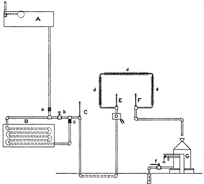
Fig. 14.—Schematic diagram of water circuit for heat-absorbers of calorimeter. A, constant-level tank from which water descends to main pipe supplying heat-absorbers; a, valve for controlling supply from tank A; B, section of piping passing into cold brine; b, valve controlling water direct from large tank A; c, valve controlling amount of water from cooling section B; C, thermometer at mixer; D, electric heater for ingoing water; E, thermometer for ingoing water; d d d, heat-absorbers inside calorimeter; F, thermometer indicating temperature of outcoming water; G, can for collecting water from calorimeter; f, valve for emptying G.
The water descends from this tank in a large 2-inch pipe to the ceiling of the calorimeter laboratory, where it is subdivided into three 1-inch pipes, so as to provide for a water-supply for three calorimeters used simultaneously, if necessary, and eliminate the influence of a variation in the rate of flow in one calorimeter upon the rate of flow in another. These pipes are brought down the inner wall of the room adjacent to the refrigeration room and part of the water circuit is passed through a brass coil immersed in a cooling-tank in the refrigeration room. By means of a by-pass, water of any degree of temperature from 2° C. to 20° C. may be obtained. The water is then conducted through a pipe beneath the floor to the calorimeter chamber, passed through the absorbers, and is finally measured in the water-meter.
A diagrammatic sketch showing the course of the water-current is given (fig. 14), in which A is the tank on the top floor controlled by the ball cock and valve, and a is the main valve which controls this supply to the cooler B, and by adjusting the valve b and valve c any desired mixture of water can be obtained. A thermometer C gives a rough idea of the temperature of the water, so as to aid in securing the proper mixture. The water then passes under the floor of the calorimeter laboratory and ascends to the apparatus D, which is used for heating it to the desired temperature before entering the calorimeter. The temperature of the water as it enters the calorimeter is measured on an accurately calibrated thermometer E, and it then passes through the absorber system d d d and leaves the calorimeter, passing the thermometer F, upon which the final temperature is read. It then passes through a pipe and falls into a large can G, placed upon scales. When this can is filled the water is deflected for a few minutes to another can and by opening valve f the water is conducted to the drain after having been weighed.
Brine-tank.—The cooling system for the water-supply consists of a tank in which there is immersed an iron coil connected by two valves to the supply and return of the brine mains from the central power-house. These valves are situated just ahead of the valves controlling the cooling device in the refrigeration room and permit the passage of brine through the coil without filling the large coils for the cooling of the air in the calorimeter laboratory. As the brine passes through this coil, which is not shown in the figure, it cools the water in which it is immersed and the water in turn cools the coil through which the water-supply to the calorimeter passes. The brass coil only is shown in the figure. The system is very efficient and we have no difficulty in cooling the water as low as 2° C. As a matter of fact our chief difficulty is in regulating the supply of brine so as not to freeze the water-supply.
Water-mixer.—If the valve b is opened, water flows through this short length of pipe much more rapidly than through the long coil, owing to the greater resistance of the cooling coil. In conducting these experiments the valve c is opened wide and by varying the amount to which the valve b is opened, the water is evenly and readily mixed. The thermometer C is in practice immersed in the water-mixer constructed somewhat after the principle of the mixer inside the chamber described on page 21. All the piping, including that under the floor, and the reheater D, are covered with hair-felt and well insulated.
Rate-valves.—It has been found extremely difficult to secure any form of valve which, even with a constant pressure of water, will give a constant rate of flow. In this type of calorimeter it is highly desirable that the rate of flow be as nearly constant as possible hour after hour, as this constant rate of flow aids materially in maintaining the calorimeter at an even temperature. Obviously, fluctuations in the rate of flow will produce fluctuations in the temperature of the ingoing water and in the amount of heat brought away. This disturbs greatly the temperature equilibrium, which is ordinarily maintained fairly constant. Just before the water enters the reheater D it is caused to pass through a rate-valve, which at present consists of an ordinary plug-cock. At present we are experimenting with other types of valves to secure even greater constancy, if possible.
Electric reheater.—In order to control absolutely the temperature of the water entering at E, it is planned to cool the water leaving the water-mixer at C somewhat below the desired temperature, so that it is necessary to reheat it to the desired point. This is done by passing a current of electricity through a coil inserted in the system at the point D. This electric reheater consists of a standard "Simplex" coil, so placed in the copper can that the water has a maximum circulation about the heater. The whole device is thoroughly insulated with hair-felt. By connecting the electric reheater with the rheostat on the observer's table, control of the quantity of electricity passing through the coil is readily obtained, and hence it is possible to regulate the temperature of the ingoing water to within a few hundredths of a degree.
The control of the amount of heat brought away from the chamber is made either by (1) increasing the rate of flow or (2) by varying the temperature of the ingoing water. Usually only the second method is necessary. In the older form of apparatus a third method was possible, namely, by varying the area of the absorbing surface of the cooling system inside of the chamber. This last method of regulation, which was used almost exclusively in earlier experiments, called for an elaborate system of shields which could be raised or lowered at will by the operator outside, thus involving an opening through the chamber which was somewhat difficult to make air-tight and also considerably complicating the mechanism inside the chamber. The more recent method of control by regulating the temperature of the ingoing water by the electric reheater has been much refined and has given excellent service.
Insulation of water-pipes through the wall.—To insulate the water-pipes as they pass through the metal walls of the calorimeter and to prevent any cooling effect not measured by the thermometers presented great difficulties. The device employed in the Middletown chamber was relatively simple, but very inaccessible and a source of more or less trouble, namely, a large-sized glass tube embedded in a large round wooden plug with the annular space between the glass and wood filled with wax. An attempt was made in the new calorimeters to secure air insulation by using a large-sized glass tube, some 15 millimeters internal diameter, and passing it through a large rubber stopper, fitting into a brass ferule soldered between the zinc and copper walls. (See N, fig. 25.) So far as insulation was concerned, this arrangement was very satisfactory, but unfortunately the glass tubes break readily and difficulty was constantly experienced. An attempt was next made to substitute hard-rubber tubing for the glass tube, but this did not prove to be an efficient insulator. More recently we have used with perfect success a special form of vacuum-jacketed glass tube, which gives the most satisfactory insulation. However, this system of insulation is impracticable when electric-resistance thermometers are used for recording the water-temperature differences and can be used only when mercurial thermometers exclusively are employed. The electric-resistance thermometers are constructed in such a way, however, as to make negligible any inequalities in the passage of heat through the hard-rubber casing. This will be seen in the discussion of these thermometers.
Measuring the water.—As the water leaves the respiration chamber it passes through a valve which allows it to be deflected either into the drain during the preliminary period, or into a small can where the measurements of the rate of flow can readily be made, or into a large tank (G, fig. 14) where the water is weighed. The measurement of the water is made by weight rather than by volume, as it has been found that the weighing may be carried out with great accuracy. The tank, a galvanized-iron ash-can, is provided with a conical top, through an opening in which a funnel is placed. The diagram shows the water leaving the calorimeter and entering the meter through this funnel, but in practice it is adjusted to enter through an opening on the side of the meter. After the valve f is tightly closed the empty can is weighed.
When the experiment proper begins the water-current is deflected so as to run into this can and at the end of an hour the water is deflected into a small can used for measuring the rate of flow. While it is running into this can, the large can G is weighed on platform scales to within 10 grams. After weighing, the water is again deflected into the large can and that collected in the small measuring can is poured into G through the funnel. The can holds about 100 liters of water and consequently from 3 to 8 one-hour periods, depending upon the rate of flow, can be continued without emptying the meter. When it is desired to empty the meter at the end of the period, the water is allowed to flow into the small can, and after weighing G, the valve f is opened. About 4 minutes are required to empty the large can. After this the valve is again closed, the empty can weighed, and the water in the small measuring-can poured into the large can G through the funnel. The scales used are the so-called silk scales and are listed by the manufacturers to weigh 150 kilograms. This form of scales was formerly used in weighing the man inside the chamber.[7]
THERMOMETERS.
In connection with the calorimeter and the accessories, mercurial and electric-resistance thermometers are employed. For measuring the temperature of the water as it enters and leaves the chamber through horizontal tubes, mercurial thermometers are used, and these are supplemented by electric-resistance thermometers which are connected with a special form of recording instrument for permanently recording the temperature differences. For the measurement of the temperatures inside of the calorimeter, two sets of electric-resistance thermometers are used, one of which is a series of open coils of wire suspended in the air of the chamber so as to take up quickly the temperature of the air. The other set consists of resistance coils encased in copper boxes soldered to the copper wall and are designed to indicate the temperature of the copper wall rather than that of the air.
MERCURIAL THERMOMETERS.
The mercurial thermometers used for measuring the temperature differences of the water-current are of special construction and have been calibrated with the greatest accuracy. As the water enters the respiration chamber through a horizontal tube, the thermometers are so constructed and so placed in the horizontal tubes through which the water passes that the bulbs of the thermometers lie about in a plane with the copper wall, thus taking the temperature of the water immediately as it enters and as it leaves the chamber. For convenience in reading, the stem of the thermometer is bent at right angles and the graduations are placed on the upright part.
The thermometers are graduated from 0° to 12° C. or from 8° to 20° C. and each degree is divided into fiftieths. Without the use of a lens it is possible to read accurately to the hundredth of a degree. For calibrating these thermometers a special arrangement is necessary. The standards used consist of well-constructed metastatic thermometers of the Beckmann type, made by C. Richter, of Berlin, and calibrated by the Physikalische Technische Reichsanstalt. Furthermore, a standard thermometer, graduated from 14° to 24° C., also made by Richter and standardized by the Physikalische Technische Reichsanstalt, serves as a basis for securing the absolute temperature. Since, however, on the mercurial thermometers used in the water-current, differences in temperature are required rather than absolute temperatures, it is unnecessary, except in an approximate way, to standardize the thermometers on the basis of absolute temperature. For calibrating the thermometers, an ordinary wooden water-pail is provided with several holes in the side near the bottom. One-hole rubber stoppers are inserted in these holes and through these are placed the bulbs and stems of the different thermometers which are to be calibrated. The upright portion of the stem is held in a vertical position by a clamp. The pail is filled with water, thereby insuring a large mass of water and slow temperature fluctuations, and the water is stirred by means of an electrically driven turbine stirrer.
The Beckmann thermometers, of which two are used, are so adjusted that they overlap each other and thus allow a range of 8° to 14° C. without resetting. For all temperatures above 14° C., the standard Richter thermometer can be used directly. For temperatures at 8° C. or below, a large funnel filled with cracked ice is placed with the stem dipping into the water. As the ice melts, the cooling effect on the large mass of water is sufficient to maintain the temperature constant and compensate the heating effect of the surrounding room-air. The thermometers are tapped and read as nearly simultaneously as possible. A number of readings are taken at each point and the average readings used in the calculations. Making due allowance for the corrections on the Beckmann thermometers, the temperature differences can be determined to less than 0.01° C. The data obtained from the calibrations are therefore used for comparison and a table of corrections is prepared for each set of thermometers used. It is especially important that these thermometers be compared among themselves with great accuracy, since as used in the calorimeter the temperature of the ingoing water is measured on one thermometer and the temperature of the outgoing water on another.
Thermometers of this type are extremely fragile. The long angle with an arm some 35 centimeters in length makes it difficult to handle them without breakage, but they are extremely sensitive and accurate and have given great satisfaction. The construction of the bulb is such, however, that the slightest pressure on it raises the column of mercury very perceptibly, and hence it is important in practical use to note the influence of the pressure of the water upon the bulbs and make corrections therefor. The influence of such pressure upon thermometers used in an apparatus of this type was first pointed out by Armsby,[8] and with high rates of flow, amounting to 1 liter or more per minute, there may be a correction on these thermometers amounting to several hundredths of a degree. We have found that, as installed at present, with a rate of flow of less than 400 cubic centimeters per minute, there is no correction for water pressure.
In installing a thermometer it is of the greatest importance that there be no pressure against the side of the tube through which the thermometer is inserted. The slightest pressure will cause considerable rise in the mercury column. Special precautions must also be taken to insulate the tube through which the water passes, as the passage of the water along the tube does not insure ordinarily a thorough mixing, and by moving the thermometer bulb from the center of the tube to a point near the edge, the water, which at the edge may be somewhat warmer than at the center, immediately affects the thermometer. By use of the vacuum jacket mentioned above, this warming of the water has been avoided, and in electric-resistance thermometers special precautions are taken not only with regard to the relative position of the bulb of the mercury thermometer and the resistance thermometer, but also with regard to the hard-rubber insulation, to avoid errors of this nature.
ELECTRIC-RESISTANCE THERMOMETERS.
Electric-resistance thermometers are used in connection with the respiration calorimeter for several purposes: first, to determine the fluctuations in the temperature of the air inside the chamber; second, to measure the fluctuations of the temperature of the copper wall of the respiration chamber; third, for determining the variations in body temperature; finally, for recording the differences in temperature of the incoming and outgoing water. While these thermometers are all built on the same principle, their installation is very different, and a word regarding the method of using each is necessary.
AIR THERMOMETERS.
The air thermometers are designed with a special view to taking quickly the temperature of the air. Five thermometers, each having a resistance of not far from 4 ohms, are connected in series and suspended 3.5 centimeters from the wall on hooks inside the chamber. They are surrounded for protection, first, with a perforated metal cylinder, and outside this with a wire guard.
Fig. 15.
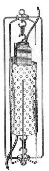
Detail of air-resistance thermometer, showing method of mounting and wiring the thermometer. Parts of the wire guard and brass guard are shown, cut away so that interior structure can be seen.
The details of construction and method of installation are shown in fig. 15. Four strips of mica are inserted into four slots in a hard maple rod 12.5 centimeters long and 12 millimeters in diameter, and around each strip is wound 5 meters of double silk-covered pure copper wire (wire-gage No. 30). By means of heavy connecting wires, five of these thermometers are connected in series, giving a total resistance of the system of not far from 20 ohms. The thermometer proper is suspended between two hooks by rubber bands and these two hooks are in turn fastened to a wire guard which is attached to threaded rods soldered to the inner surface of the copper wall, thus bringing the center of the thermometer 3.4 centimeters from the copper wall. Two of these thermometers are placed in the dome of the calorimeter immediately over the shoulders of the subject, and the other three are distributed around the sides and front of the chamber. This type of construction gives maximum sensibility to the temperature fluctuations of the air itself and yet insures thorough protection. The two terminals are carried outside of the respiration chamber to the observer's table, where the temperature fluctuations are measured on a Wheatstone bridge.
WALL THERMOMETERS.
The wall thermometers are designed for the purpose of taking the temperature of the copper wall rather than the temperature of the air. When temperature fluctuations are being experienced inside of the respiration chamber, the air obviously shows temperature fluctuations first, and the copper walls are next affected. Since in making corrections for the hydrothermal equivalent of the apparatus and for changes in the temperature of the apparatus as a whole it is desirable to know the temperature changes of the wall rather than the air, these wall thermometers were installed for this special purpose. In construction they are not unlike the thermometers used in the air, but instead of being surrounded by perforated metal they are encased in copper boxes soldered directly to the wall. Five such thermometers are used in series and, though attached permanently to the wall, they are placed in relatively the same position as the air thermometers. The two terminals are conducted through the metal walls to the observer's table, where variations in resistance are measured. The resistance of the five thermometers is not far from 20 ohms.
ELECTRICAL RECTAL THERMOMETER.
The resistance thermometer used for measuring the temperature of the body of the man is of a somewhat different type, since it is necessary to wind the coil in a compact form, inclose it in a pure silver tube, and connect it with suitable rubber-covered connections, so that it can be inserted deep in the rectum. The apparatus has been described in a number of publications.[9] The resistance of this system is also not far from 20 ohms, thus simplifying the use of the apparatus already installed on the observer's table.
ELECTRIC-RESISTANCE THERMOMETERS FOR THE WATER-CURRENT.
The measurement of the temperature differences of the water-current by the electric-resistance thermometer was tried a number of years ago by Rosa,[10] but the results were not invariably satisfactory and in all the subsequent experimenting the resistance thermometer could not be used with satisfaction. More recently, plans were made to incorporate some of the results of the rapidly accumulating experience in the use of resistance thermometers and consequently an electric-resistance thermometer was devised to meet the conditions of experimentation with the respiration calorimeter by Dr. E. F. Northrup, of the Leeds & Northrup Company, of Philadelphia. The conditions to be met were that the thermometers should take rapidly the temperature of the ingoing and outcoming water and that the fluctuations in temperature difference as measured by the resistance thermometers should be controlled for calibration purposes by the differences in temperature of the mercurial thermometers.
Fig. 16.—Details of resistance thermometers for water-circuit. Upper part of figure shows a sketch of the outside of the hard-rubber case. In lower part is a section showing interior construction. Flattened lead tube wound about central brass tube contains the resistance wire. A is enlarged part of the case forming a chamber for the mercury bulb. Arrows indicate direction of flow on resistance thermometer for ingoing water.
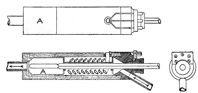
For the resistance thermometer, Dr. Northrup has used, instead of copper, pure nickel wire, which has a much higher resistance and thus enables a much greater total resistance to be inclosed in a given space. The insulated nickel wire is wound in a flattened spiral and then passed through a thin lead tube flattened somewhat. This lead tube is then wound around a central core and the flattened portions attached at such an angle that the water passing through the tubes has a tendency to be directed away from the center and against the outer wall, thus insuring a mixing of the water. Space is left for the insertion of the mercurial thermometer. With the thermometer for the ingoing water, it was found necessary to extend the bulb somewhat beyond the resistance coil, so that the water might be thoroughly mixed before reaching the bulb and thus insure a steady temperature. Thus it was found necessary to enlarge the chamber A (fig. 16) somewhat and the tube leading out of the thermometer, so that the bulb of the thermometer itself could be placed almost directly at the opening of the exit tube. Under these conditions perfect mixing of water and constancy of temperature were obtained.
In the case of the thermometer which measured the outcoming water, the difficulty was not so great, as the outcoming water is somewhat nearer the temperature of the chamber, and the water as it leaves the thermometer passes first over the mercurial thermometer and then over the resistance thermometer. By means of a long series of tests it was found possible to adjust these resistance thermometers so that the variations in resistance were in direct proportion to the temperature changes noted on the mercurial thermometers. Obviously, these differences in resistance of the two thermometers can be measured directly with the Wheatstone bridge, but, what is more satisfactory, they are measured and recorded directly on a special type of automatic recorder described beyond.
OBSERVER'S TABLE.
The measurements of the temperature of the respiration chamber, of the water-current, and of the body temperature of the man, as well as the heating and cooling of the air-spaces about the calorimeter, are all under the control of the physical assistant. The apparatus for these temperature controls and measurements is all collected compactly on a table, the so-called "observer's table." At this, the physical assistant sits throughout the experiments. For convenience in observing the mercurial thermometers in the water-current and general inspection of the whole apparatus, this table is placed on an elevated platform, shown in fig. 3. Directly in front of the table the galvanometer is suspended from the ceiling and a black hood extends from the observer's table to the galvanometer itself. On the observer's table proper are all the electrical connections and at the left are the mercurial thermometers for the chair calorimeter. Formerly, when the method of alternately cooling and heating the air-spaces was used, the observer was able to open and close the water-valves without leaving the chair.
The observer's table is so arranged electrically as to make possible temperature control and measurement of either of the two calorimeters. It is impossible, however, for the observer to read the mercurial thermometers in the bed calorimeter without leaving his chair, and likewise he must occasionally alter the cooling water flowing through the outer air-spaces by going to the bed calorimeter itself. The installation of the electric-resistance thermometers connected with the temperature recorder does away with the reading of the mercurial thermometers, save for purposes of comparison, and hence it is unnecessary for the assistant to leave the chair at the observer's table when the bed calorimeter is in use. Likewise the substitution of the method of continuously cooling somewhat the air-spaces and reheating with electricity, mentioned on page 18, does away with the necessity for alternately opening and closing the water-valves of the chair calorimeter placed at the left of the observer's table.
Fig. 17.—Diagram of wiring of observer's table. W1, W2, Wheatstone bridges for resistance thermometers; K1, K2, double contact keys for controlling Wheatstone circuits; S1, S2, S3, double-pole double-throw switches for changing from chair to bed calorimeter; S4, double-pole double-throw switch for changing from wall to air thermometers; G, galvanometer; R2, rheostat. 1, 2, 3, 4, 5, wires connecting with resistance-coils A B D E F and a b d e f; S2, 6-point switch for connecting thermal-junction circuits of either bed or chair calorimeter with galvanometer; S10, 10-point double-throw switch for changing heating circuits and thermal-junction circuits to either chair or bed calorimeter; R1, rheostat for controlling electric heaters in ingoing water in calorimeters; S8, double-pole single-throw switch for connecting 110-v. current with connections on table; S9, double-pole single-throw switch for connecting R1 with bed calorimeter.
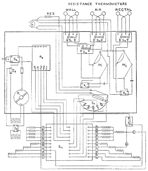
Of special interest are the electrical connections on the observer's table itself. A diagrammatic representation of the observer's table with its connections is shown in fig. 17. The heavy black outline gives in a general way the outline of the table proper and thus shows a diagrammatic distribution of the parts. The first of the electrical measurements necessary during experiments is that of the thermo-electric effect of the thermal junction systems installed on the calorimeters. To aid in indicating what parts of the zinc wall need cooling or heating, the thermal junction systems are, as has already been described, separated into four sections on the chair calorimeter and three sections on the bed calorimeter; in the first calorimeter, the top, front, rear, and bottom; in the bed calorimeter, the top, sides, and bottom.
CONNECTIONS TO THERMAL-JUNCTION SYSTEMS.
Since heretofore it has been deemed unwise to attempt to use both calorimeters at the same time, the electrical connections are so made that, by means of electrical switches, either calorimeter can be connected to the apparatus on the table.
The thermal-junction measurements are made by a semicircular switch S7. The various points, i, ii, iii, iv, etc., are connected with the different thermal-junction systems. Thus, by following the wiring diagram, it can be seen that the connections with i run to the different binding-posts of the switch S10, which as a matter of fact is placed beneath the table. This switch S10 has three rows of binding-posts. The center row connects directly with the apparatus on the observer's table, the outer rows connect with either the chair calorimeter or the bed calorimeter. The points marked a, b, d, e, f, etc., connect with the bed calorimeter and A, B, D, etc., connect with the chair calorimeter. Thus, by connecting the points g and i with the two binding-posts opposite them on the switch S10, it can be seen that this connection leads directly to the point i on the switch S7, and as a matter of fact this gives direct connection with the galvanometer through the key on S7, thus connecting the thermal-junction system on one section of the bed calorimeter between g and i directly with the galvanometer. Similar connections from the other points can readily be followed from the diagram. The points on the switch S7 indicated as i, ii, iii, iv, correspond respectively to the thermal-junction systems on the top, rear, front, and bottom of the chair calorimeter.
By following the wiring diagram of the point v, it will be seen that this will include the connections with the thermal junctions connected in series and thus give a sum total of the electromotive forces in the thermal junctions. The point vi is connected with the thermal-junction system in the air system, indicating the differences in temperature between the ingoing and outgoing air. It will be noted that there are four sections in the chair calorimeter, while in the bed calorimeter there are but three, and hence a special switch S3 is installed to insure proper connections when the bed calorimeter is in use.
This system of connecting the thermal junctions in different sections to the galvanometer makes possible a more accurate control of the temperatures in the various parts, and while the algebraic sum of the temperature differences of the parts may equal zero, it is conceivable that there may be a condition in the calorimeter when there is a considerable amount of heat passing out through the top, for example, compensated exactly by the heat which passes in at the bottom, and while with the top section there would be a large plus deflection on the galvanometer, thus indicating that the air around the zinc wall was too cold and that heat was passing out, there would be a corresponding minus deflection on the bottom section, indicating the reverse conditions. The two may exactly balance each other, but it has been found advantageous to consider each section as a unit by itself and to attempt delicate temperature control of each individual unit. This has been made possible by the electrical connections, as shown on the diagram.
RHEOSTAT FOR HEATING.
The rheostat for heating the air-spaces and the returning air-current about the zinc wall is placed on the observer's table and is indicated in the diagram as R2. There are five different sets of contact-points, marked 1, 2, 3, 4, and 5. One end of the rheostat is connected directly with the 110-volt circuit through the main switch S5. The other side of the switch S5 connects directly with the point on the middle of switch S10, and when this middle point is joined with either f and F, direct connection is insured between all the various heating-circuits on the calorimeter in use. The various numbered points on the rheostat R2, are connected with the binding posts on S10, and each can in turn be connected with a or A, b or B, etc. The heating of the top of the chair calorimeter is controlled by the point 5 on the rheostat R2, the rear by the point 4, the front by the point 3, and the bottom by the point 2. Point 1 is used for heating the air entering the calorimeter by means of an electric lamp placed in the air-pipe, as shown in fig. 25.
The warming of the electrical reheater placed in the water-circuit just before the water enters the calorimeter is done by an electrical current controlled by the resistance R1. This R1 is connected on one end directly with the 110-volt circuit and the current leaving it passes through the resistance inside the heater in the water-current. The two heaters, one for each calorimeter, are indicated on the diagram above and below the switch S9. The disposition of the switches is such as to make it possible to use alternately the reheaters on either the bed or the chair calorimeter, and the main resistance R1 suffices for both.
WHEATSTONE BRIDGES.
For use in measuring the temperature of the air and of the copper wall of the calorimeters, as well as the rectal temperature of the subject, a series of resistance thermometers is employed. These are so connected on the observer's table that they may be brought into connection with two Wheatstone bridges, W1 and W2. Bridge W1 is used for the resistance thermometers indicating the temperature of the wall and the air. Bridge W2 is for the rectal thermometer. Since similar thermometers are inserted in both calorimeters, it is necessary to introduce some switch to connect either set at will and hence the double-throw switches S1, S2, and S3 allow the use of either the wall, air, or rectal thermometer on either the bed or chair calorimeter at will. Since the bridge W1 is used for measuring the temperature of both the wall and the air, a fourth double-pole switch, S4, is used to connect the air and wall thermometers alternately. The double-contact key, K1, is connected with the bridge W1 and is so arranged that the battery circuit is first made and subsequently the galvanometer circuit. A similar arrangement in K2 controls the connections for the bridge W2.
GALVANOMETER.
The galvanometer is of the Deprez-d'Arsonval type and is extremely sensitive. The sensitiveness is so great that it is desirable to introduce a resistance of some 500 ohms into the thermal-junction circuits. This is indicated at the top of the diagram near the galvanometer. The maximum sensitiveness of the galvanometer is retained when the connection is made with the Wheatstone bridges. The galvanometer is suspended from the ceiling of the calorimeter laboratory and is free from vibration.
RESISTANCE FOR HEATING COILS.
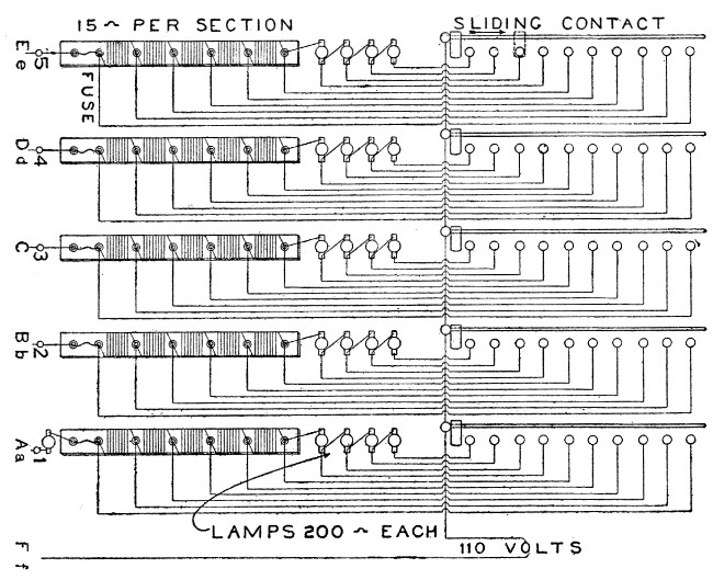
To vary the current passing through the manganin heating coils in the air-spaces next the zinc wall, a series of resistances is installed connected directly with the rheostat R2 in fig. 17. The details of these resistances and their connection with the rheostat are shown in fig. 18. The rheostat, which is in the right part of the figure, has five sliding contacts, each of which can be connected with ten different points. One end of the rheostat is connected directly with the 110-volt circuit. Beneath the observer's table are fastened the five resistances, which consist of four lamps, each having approximately 200 ohms resistance and then a series of resistance-coils wound on a long strip of asbestos lumber, each section having approximately 15 ohms between the binding-posts. A fuse-wire is inserted in each circuit to protect the chamber from excessive current. Of these resistances, No. 1 is used to heat the lamp in the air-current shown in fig. 25, and consequently it has been found advisable to place permanently a second lamp in series with the first, but outside of the air-pipe, so as to avoid burning out the lamp inside of the air-pipe. The other four resistances, 2, 3, 4, and 5, are connected with the different sections on the two calorimeters. No. 5 corresponds to the top of both calorimeters. No. 4 corresponds to the rear section of the chair calorimeter and to the sides of the bed calorimeter. No. 3 corresponds to the front of the chair calorimeter and is without communication with the bed calorimeter. No. 2 connects with the bottom of both calorimeters.
It will be seen from the diagrams that each of these resistances can be connected at will with either the bed or the chair calorimeter and at such points as are indicated by the lettering below the numbers. Thus, section 1 can be connected with either the point A or point a on fig. 17 and thus directly control the amount of current passing through the corresponding resistance in series with the lamp in the air-current. The sliding contacts at present in use are ill adapted to long-continued usage and will therefore shortly be substituted by a more substantial instrument. The form of resistance using small lamps and the resistance wires wound on asbestos lumber has proven very satisfactory and very compact in form.
Fig. 18.—Diagram of rheostat and resistances in series with it. At the right are shown the sliding contacts, and in the center places for lamps used as resistances, and to left the sections of wire resistances.
TEMPERATURE RECORDER.
The numerous electrical, thermometric, and chemical measurements necessary in the full conduct of an experiment with the respiration calorimeter has often raised the question of the desirability of making at least a portion of these observations more or less automatic. This seems particularly feasible with the observations ordinarily recorded by the physical observer. These observations consist of the reading of the mercurial thermometers indicating the temperatures of the ingoing and outcoming water, records with the electric-resistance thermometers for the temperature of the air and the walls and the body temperatures, and the deflections of the thermo-electric elements.
Numerous plans have been proposed for rendering automatic some of these observations, as well as the control of the heating and cooling of the air-circuits. Obviously, such a record of temperature measurements would have two distinct advantages: (1) in giving an accurate graphic record which would be permanent and in which the influence of the personal equation would be eliminated; (2) while the physical observer at present has much less to do than with the earlier form of apparatus, it would materially lighten his labors and thereby tend to minimize errors in the other observations.
The development of the thread recorder and the photographic registration apparatus in recent years led to the belief that we could employ similar apparatus in connection with our investigations in this laboratory. To this end a number of accurate electrical measuring instruments were purchased, and after a number of tests it was considered feasible to record automatically the temperature differences of the ingoing and outcoming water from the calorimeter. Based upon our preliminary tests, the Leeds & Northrup Company of Philadelphia, whose experience with such problems is very extended, were commissioned to construct an apparatus to meet the requirements of the respiration calorimeter. The conditions to be met by this apparatus were such as to call for a registering recorder that would indicate the differences in temperature between the ingoing and outcoming water to within 0.5 per cent and to record these differences in a permanent ink line on coordinate paper. Furthermore, the apparatus must be installed in a fixed position in the laboratory, and connections should be such as to make it interchangeable with any one of five calorimeters.
After a great deal of preliminary experimenting, in which the Leeds & Northrup Company have most generously interpreted our specifications, they have furnished us with an apparatus which meets to a high degree of satisfaction the conditions imposed. The thermometers themselves have already been discussed. (See page 30.) The recording apparatus consists of three parts: (1) the galvanometer; (2) the creeper or automatic sliding-contact; (3) the clockwork for the forward movement of the roll of coordinate paper and to control the periodic movement of the creeper.
Under ordinary conditions with rest experiments in the chair calorimeter or bed calorimeter, the temperature differences run not far from 2° to 4°. Thus, it is seen that if the apparatus is to meet the conditions of the specifications it must measure differences of 2° C. to within 0.01° C. Provision has also been made to extend the measurement of temperature differences with the apparatus so that a difference of 8° can be measured with the same percentage accuracy.
FUNDAMENTAL PRINCIPLE OF THE APPARATUS.
The apparatus depends fundamentally upon the perfect balancing of the two sides of a differential electric circuit. A conventional diagram, fig. 19, gives a schematic outline of the connections. The two galvanometer coils, fl and fr, are wound differentially and both coils most carefully balanced so that the two windings have equal temperature coefficients. This is done by inserting a small shunt y, parallel with the coil fl, and thus the temperature coefficient of fl and fr are made absolutely equal. The two thermometers are indicated as T1 and T2 and are inserted in the ingoing and outgoing water respectively. A slide-wire resistance is indicated by J, and r is the resistance for the zero adjustment. Ba, Z, and Z1 are the battery and its variable series resistances. If T1 and T2 are exactly of the same temperature, i. e., if the temperature difference of the ingoing and outcoming water is zero, the sliding contact q stands at 0 on the slide-wire and thus the resistance of the system from 0 through fl, r, and T1 back to the point C is exactly the same as the resistance of the slide-wire J plus the coil fr plus T2 back to the point C. A rise in temperature of T2 gives an increase of resistance in the circuit and the sliding contact q moves along the slide-wire toward J maximum until a balance is obtained.
Fig. 19.—Diagram of wiring of differential circuit with its various shunts, used in connection with resistance thermometers on water-circuit of bed calorimeter.
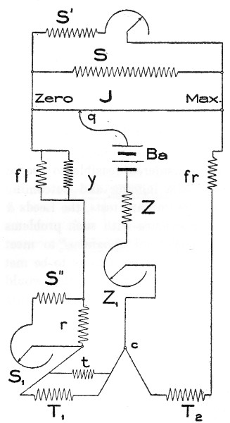
Provision is made for automatically moving the contact q by electrical means and thus the complete balance of the two differential circuits is maintained constant from second to second. As the contact q is moved, it carries with it a stylographic pen which travels in a straight line over a regularly moving roll of coordinate paper, thus producing a permanently recorded curve indicating the temperature differences. The slide-wire J is calibrated so that any inequalities in the temperature coefficient of the thermometer wires are equalized and also so that any unit-length on the slide-wire taken at any point along the temperature scale represents a resistance equal to the resistance change in the thermometer for that particular change in temperature. With the varying conditions to be met with in this apparatus, it is necessary that varying values should be assigned at times to J and to r. This necessitates the use of shunts, and the recording range of the instrument can be easily varied by simple shunting, i. e., by changing the resistance value of J and r, providing these resistances unshunted have a value which takes care of the highest obtained temperature variations.
Fig. 19 shows the differential circuit complete with all its shunts. S is a fixed shunt to obtain a range on J; S' is a variable shunt to permit very slight variations of J within the range to correct errors due to changing of the initial temperatures of the thermometers; y is a permanent shunt across the galvanometer coil fl, to make the temperature coefficients of fl and fr absolutely equal; Z is the variable resistance in the battery-circuit to keep the current constant; r is a permanent resistance to fix the zero on varying ranges; S'' plus S1 constitutes a variable shunt to permit slight variations of r to finally adjust 0 after S' is fixed and t is a permanent shunt across the thermometer T1 to make the temperature coefficient of T1 equal to that of T2.
The apparatus can be used for measuring temperature differences from 0° to 4° or from 0° to 8°. When on the 0° to 8° range, the shunt S is open-circuited and the shunt S' alone used. The value of S, then, is predetermined so as to affect the value of the wire J and thus halve its influence in maintaining the balance. Similarly, when the lower range, i. e., from 0° to 4°, is used, the resistance r is employed, and when the higher range is used another value to r must be given by using a plug resistance-box, in the use of which the resistance r is doubled.
The resistance S'' and S1 are combined in a slide-wire resistance-box and are used to change the value of the whole apparatus when there are marked changes in the position of the thermometric scale. Thus, if the ingoing water is at 2° C. and the outcoming water at 5° C. in one instance, and in another instance the ingoing water is 13° and the outgoing water is 15°, a slight alteration in the value of S1, and also of S', is necessary in order to have the apparatus draw a curve to represent truly the temperature differences. These slight alterations are determined beforehand by careful tests and the exact value of the resistances in S' and in S1 are permanently recorded for subsequent use.
THE GALVANOMETER.
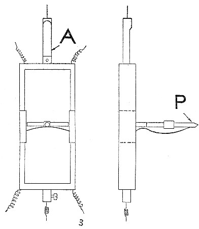
The galvanometer is of the Deprez-d'Arsonval type and has a particularly powerful magnetic field, in which a double coil swings suspended similar to the marine galvanometer coils. This coil is protected from vibrations by an anti-vibration tube A, fig. 20, and carries a pointer P which acts to select the direction of movement of the recording apparatus, the movable contact point q, fig. 19. In front of this galvanometer coil and inclosed in the same air-tight metal case is the plunger contact Pl, fig. 21. The galvanometer pointer P swings freely below the silver contacts S1 and S2, just clearing the ivory insulator i. The magnet plunger makes a contact depending upon the adjustment of a clock at intervals of 2 seconds. So long as both galvanometer coils are influenced by exactly the same strength of current, the pointer will stand in line with and immediately below i and no current passes through the recording apparatus. Any disturbance of the electrical equilibrium causes the pointer P to swing either toward S1 or S2, thus completing the circuit at either the right hand or the left hand, at intervals of 2 seconds. The movement of the pointer away from its normal position exactly beneath i to either S1 on the left hand or S2 on the right, results from an inequality in the current flowing through the two coils in the galvanometer. The difference in the two currents passing through these coils is caused by a change in temperatures of the two thermometers in the water circuit.
Fig. 20.—Diagram of galvanometer coil used in connection with recording apparatus for resistance thermometers in the water-circuit of bed calorimeter. A, anti-vibration tube; P, pointer.
THE CREEPER.
The movement of the sliding-contact q, fig. 19, along the slide-wire J, is produced by means of a special device called a creeper, consisting of a piece of brass carefully fitted to a threaded steel rod some 30 centimeters long. The movement of this bar along this threaded rod accomplishes two things. The bar is in contact with the slide-wire J and therefore varies the position of the point q and it also carries with it a stylographic pen. The movements of this bar to the right or the left are produced by an auxiliary electric current, the contact of which is made by a plunger-plate forcing the pointer P against either S1 or S2. P makes the contact between Pl and either S1 or S2 and sends a current through solenoids at either the right or the left of the creeper. At intervals of every 2 seconds the plunger rises and forces the pointer P against either S1, i, or S2 above. The movement of this plunger is controlled by a current from a 110-volt circuit, the connections of which are shown in fig. 22. If the contact is made at T, the current passes through 2,600 ohms, directly across the 110-volt circuit, and consequently there is no effective current flowing through the plunger Pl. When the contact T is open, the current flows through the plunger in series with 2,600 ohms resistance. T is opened automatically at intervals of 2 seconds by the clock.
Fig. 21.—Diagram of wiring of circuits actuating plunger and creeper.
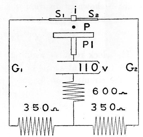
Fig. 22.—Diagram of wiring of complete 110-volt circuit.
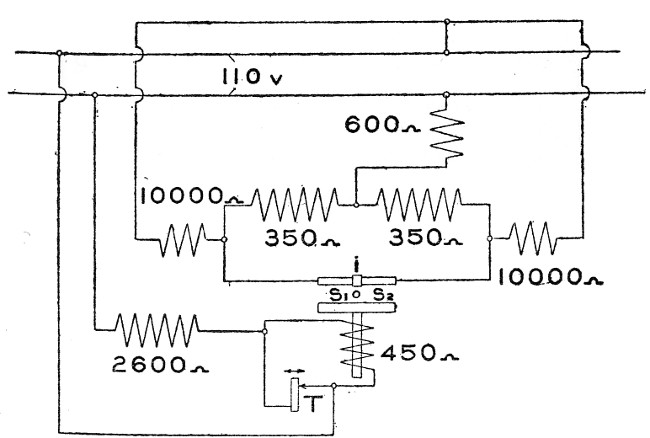
The movement of the contact arm along the threaded rod is produced by the action of either one of two solenoids, each of which has a core attached to a rack and pinion at either end of the rod. If the current is passed through the contact S1, a current passes through the left-hand solenoid, the core moves down, the rack on the core moves the pinion on the rod through a definite fraction of a complete revolution and this movement forces the creeper in one direction. Conversely, the passing of the current through the solenoid at the other end of the threaded rod moves the creeper in the other direction. The distance which the iron rack on the end of the core is moved is determined carefully, so that the threaded rod is turned for each contact exactly the same fraction of a revolution. For actuating these solenoids, the 110-volt circuit is again used. The wire connections are shown in part in fig. 21, in which it is seen that the current passes through the plunger-contact and through the pointer P to the silver plate S1 and then along the line G1 through 350 ohms wound about the left-hand solenoid back through a 600-ohm resistance to the main line. The use of the 110-volt current under such circumstances would normally produce a notable sparking effect on the pointer P, and to reduce this to a minimum there is a high resistance, amounting to 10,000 ohms on each side, shunted between the main line and the creeper connections. This shunt is shown in diagram in fig. 22. Thus there is never a complete open circuit and sparking is prevented.
THE CLOCK.
The clock requires winding every week and is so geared as to move the paper forward at a rate of 3 inches per hour. The contact-point for opening the circuit T on fig. 22 is likewise connected with one of the smaller wheels of the clock. This contact is made by tripping a little lever by means of a toothed wheel of phosphor-bronze.
INSTALLATION OF THE APPARATUS.
Fig. 23 Temperature recorder. The recorder with the coordinate paper in the lower box with a glass door. A curve representing the temperature difference between the ingoing and outgoing water is directly drawn on the coordinate paper. Above are three resistance boxes, and the switches for electrical connections are at the right. On the top shelf is the galvanometer, and immediately beneath, the plug resistance box for altering the value of certain shunts.
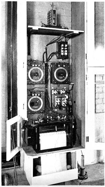
Fig. 24.—Detailed wiring diagram showing all parts of recording apparatus, together with wiring to thermometers complete, including all previous figures.
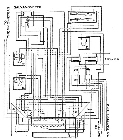
The whole apparatus is permanently and substantially installed on the north wall of the calorimeter laboratory. A photograph showing the various parts and their installation is given in fig. 23. On the top shelf is seen the galvanometer and on the lower shelf the recorder with its glass door in front and the coordinate paper dropping into the box below. The curve drawn on the coordinate paper is clearly shown. Above the recorder are the resistance-boxes, three in number, the lower one at the left being the resistance S1, the upper one at the left being the resistance S', and the upper one at the right being the resistance Z1. Immediately above the resistance-box Z1 is shown the plug resistance-box which controls on the one hand the resistance r and on the other hand the resistance S, both of which are substantially altered when changing the apparatus to register from the 0° to 4° scale to the 0° to 8° scale. A detailed wiring diagram is given in fig. 24.
TEMPERATURE CONTROL OF THE INGOING AIR.
Fig. 25.—Section of calorimeter walls and part of ventilating air-circuit, showing part of pipes for ingoing air and outgoing air. On the ingoing air-pipe at the right is the lamp for heating the ingoing air. Just above it, H is the quick-throw valve for shutting off the tension equalizer IJ. I is the copper portion of the tension equalizer, while J is the rubber diaphragm; K, the pet-cock for admitting oxygen; F, E, G, the lead pipe conducting the cold water for the ingoing air; and C, the hair-felt insulation. N, N are brass ferules soldered into the copper and zinc walls through which air-pipes pass; M, a rubber stopper for insulating the air-pipe from the calorimeter; O, the thermal junctions for indicating differences of temperature of ingoing and outgoing air and U, the connection to the outside; QQ, exits for the air-pipes from the box in which thermal junctions are placed; P, the dividing plate separating the ingoing and outgoing air; R, the section of piping conducting the air inside the calorimeter; S, a section of piping through which the air passes from the calorimeter; A, a section of the copper wall; Y, a bolt fastening the copper wall to the 2-1/2 inch angle W; B, a portion of zinc wall; C, hair-felt lining of asbestos wall D; T-J, a thermal junction in the walls.
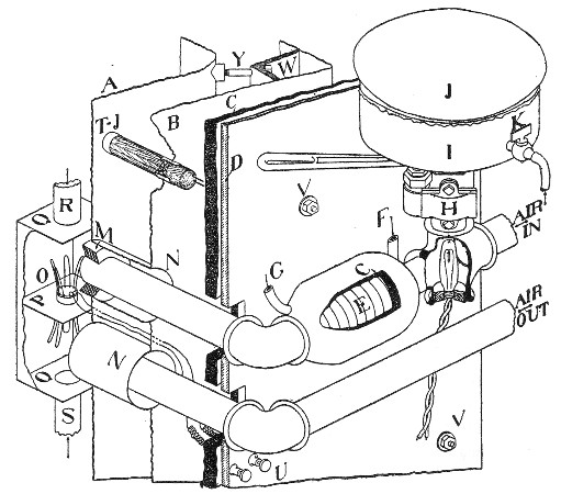
In passing the current of air through the calorimeter, temperature conditions may easily be such that the air entering is warmer than the outcoming air, in which case heat will be imparted to the calorimeter, or the reverse conditions may obtain and then heat will be brought away. To avoid this difficulty, arrangements are made for arbitrarily controlling the temperature of the air as it enters the calorimeter. This temperature control is based upon the fact that the air leaving the chamber is caused to pass over the ends of a series of thermal junctions shown as O in fig. 25. These thermal junctions have one terminal in the outgoing air and the other in the ingoing air, and consequently any difference in the temperature of the two air-currents is instantly detected by connecting the circuit with the galvanometer. Formerly the temperature control was made a varying one, by providing for either cooling or heating the ingoing air as the situation called for. The heating was done by passing the current through an electric lamp placed in the cross immediately below the tension equalizer J. Cooling was effected by means of a current of water through the lead pipe E closely wrapped around the air-pipe, water entering at F and leaving at G. This lead pipe is insulated by hair-felt pipe-covering, C. More recently, we have adopted the procedure of passing a continuous current of water, usually at a very slow rate, through the lead pipe E and always heating the air somewhat by means of the lamp, the exact temperature control being obtained by varying the heating effect of the lamp itself. This has been found much more satisfactory than by alternating from the cooling system to the heating system. In the case of the air-current, however, it is unnecessary to have the drop-sight feed-valve as used for the wall control, shown in fig. 13.
THE HEAT OF VAPORIZATION OF WATER.
During experiments with man not all the heat leaves the body by radiation and conduction, since a part is required to vaporize the water from the skin and lungs. An accurate measurement of the heat production by man therefore required a knowledge of the amount of heat thus vaporized. One of the great difficulties in the numerous forms of calorimeters that have been used heretofore with man is that only that portion of heat measured by direct radiation or conduction has been measured and the difficulties attending the determination of water vaporized have vitiated correspondingly the estimates of the heat production. Fortunately, with this apparatus the determinations of water are very exact, and since the amount of water vaporized inside the chamber is known it is possible to compute the heat required to vaporize this water by knowing the heat of vaporization of water.
Since the earlier reports describing the first form of calorimeters were written, there has appeared a research by one of our former associates, Dr. A. W. Smith[11] who, recognizing the importance of knowing exactly the heat of vaporization of water at 20°, has made this a special object of investigation. When connected with our laboratory a number of experiments were made by Doctors Smith and Benedict in an attempt to determine the heat of vaporization of water directly in a large calorimeter; but for lack of time and pressure of other experimental work it was impossible to complete the investigation. Subsequently Dr. Smith has carried out the experiments with the accuracy of exact physical measurements and has given us a very valuable series of observations.
Using the method of expressing the heat of vaporization in electrical units, Smith concludes that the heat of vaporization of water between 14° and 40° is given by the formula
L (in joules) = 2502.5 - 2.43T
and states that the "probable error" of values computed from this formula is 0.5 joule. The results are expressed in international joules, that is, in terms of the international ohm and 1.43400 for the E.M.F. of the Clark cell at 15° C., and assuming that the mean calorie is equivalent to 4.1877 international joules,[12] the formula reads
L (in mean calories) = 597.44 - 0.580T
With this formula Smith calculates that at 15° the heat of vaporization of water is equal to 588.73 calories; at 20°, 585.84 calories; at 25°, 582.93 calories; at 30°, 580.04 calories;[13] and at 35°, 577.12 calories. In all of the calculations in the researches herewith we have used the value found by Smith as 586 calories at 20°. Inasmuch as all of our records are in kilo-calories, we multiply the weight of water by the factor 0.586 to obtain the heat of vaporization.
THE BED CALORIMETER.
The chair calorimeter was designed for experiments to last not more than 6 to 8 hours, as a person can not remain comfortably seated in a chair much longer than this time. For longer experiments (experiments during the night and particularly for bed-ridden patients) a type of calorimeter which permits the introduction of a couch or bed has been devised. This calorimeter has been built, tested, and used in a number of experiments with men and women. The general shape of the chamber is given in fig. 26. The principles involved in the construction of the chair calorimeter are here applied, i. e., the use of a structural-steel framework, inner air-tight copper lining, outer zinc wall, hair-felt insulation, and outer asbestos panels. Inside of the chamber there is a heat-absorbing system suspended from the ceiling, and air thermometers and thermometers for the copper wall are installed at several points. The food-aperture is of the same general type and the furniture here consists simply of a sliding frame upon which is placed an air-mattress. The opening is at the front end of the calorimeter and is closed by two pieces of plate glass, each well sealed into place by wax after the subject has been placed inside of the chamber. Tubes through the wall opposite the food-aperture are used for the introduction of electrical connections, ingoing and outgoing water, the air-pipes, and connections for the stethoscope, pneumograph, and telephone.
The apparatus rests on four heavy iron legs. Two pieces of channel iron are attached to these legs and the structural framework of the calorimeter chamber rests upon these irons. The method of separating the asbestos outer panels is shown in the diagram. In order to provide light for the chamber, the outer wall in front of the glass windows is made of glass rather than asbestos. The front section of the outer casing can be removed easily for the introduction of a patient.
In this chamber it is impossible to weigh the bed and clothing, and hence this calorimeter can not be used for the accurate determination of the moisture vaporized from the lungs and skin of the subject, since here (as in almost every form of respiration chamber) it is absolutely impossible to distinguish between the amount of water vaporized from bed-clothing and that vaporized from the lungs and skin of the subject. With the chair calorimeter, the weighing arrangements make it possible to weigh the chair, clothing, etc., and thus apportion the total water vaporized between losses from the chair, furniture, and body of the man. In view of the fact that the water vaporized from the skin and lungs could not be determined, the whole interior of the chamber of the bed calorimeter has been coated with a white enamel paint, which gives it a bright appearance and makes it much more attractive to new patients. An incandescent light placed above the head at the front illuminates the chamber very well, and as a matter of fact the food-aperture is so placed that one can lie on the cot and actually look outdoors through one of the laboratory windows.
Fig. 26.—Cross-section of bed calorimeter, showing part of steel construction, also copper and zinc walls, food-aperture, and wall and air-resistance thermometers. Cross-section of opening, cross-section of panels of insulating asbestos, and supports of calorimeter itself are also indicated.
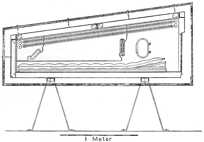
Special precaution was taken with this calorimeter to make it as comfortable and as attractive as possible to new and possibly apprehensive patients. The painting of the walls unquestionably results in a condensation of more or less moisture, for the paint certainly absorbs more moisture than does the metallic surface of the copper. The chief value of the determination of the water vaporized inside of the chamber during an experiment lies, however, not in a study of the vaporization of water as such, but in the fact that a certain amount of heat is required to vaporize the water and obviously an accurate measure of the heat production must involve a measure of the amount of water vaporized. So far as the measurement of heat is concerned, it is immaterial whether the water is vaporized from the lungs or skin of the subject or the clothing, bedding, or walls of the chamber; since for every gram of water vaporized inside of the chamber, from whatever source, 0.586 calorie of heat must have been absorbed.
The apparatus as perfected is very sensitive. The sojourn in the chamber is not uncomfortable; as a matter of fact, in an experiment made during January, 1909, the subject remained inside of the chamber for 30 hours. With male patients no difficulty is experienced in collecting the urine. No provision is made for defecation, and hence it is our custom in long experiments to empty the lower bowel with an enema and thus defer as long as possible the necessity for defecation. With none of the experiments thus far made have we experienced any difficulty in having to remove the patient because of necessity to defecate in the cramped quarters. It is highly probable that, with the majority of sick patients, experiments will not extend for more than 8 or 10 hours, and consequently the apparatus as designed should furnish most satisfactory results.