CALORIMETER LABORATORY.
Reading edition
The laboratory room is entered from the main hall by a double door. The room is 14.2 meters long by 10.1 meters wide, and is lighted on three sides by 7 windows. Since the room faces the north, the temperature conditions are much more satisfactory than could be obtained with any other exposure. In constructing the building the use of columns in this room was avoided, as they would interfere seriously with the construction of the calorimeters and accessory apparatus. Pending the completion of the five calorimeters designed for this room a temporary wooden floor was laid, thus furnishing the greatest freedom in placing piping and electric wiring beneath the floor. As fast as the calorimeters are completed, permanent flooring with suitably covered trenches for pipes is to be laid. The room is amply lighted during the day, the windows being very high, with glass transoms above. At night a large mercury-vapor lamp in the center of the room, supplemented by a number of well-placed incandescent electric lights, gives ample illumination.
GENERAL PLAN OF CALORIMETER LABORATORY.
The general plan of the laboratory and the distribution of the calorimeters and accessory apparatus are shown in fig. 1. The double doors lead from the main hall into the room. In general, it is planned to conduct all the chemical and physical observations as near the center of the laboratory as possible, hence space has been reserved for apparatus through the center of the room from south to north. The calorimeters are on either side. In this way there is the greatest economy of space and the most advantageous arrangement of apparatus.
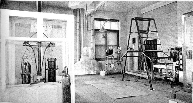
At present two calorimeters are completed, one under construction, and two others are planned. The proposed calorimeters are to be placed in the spaces inclosed by dotted lines. Of the calorimeters that are completed, the so-called chair calorimeter, which was the first built, is in the middle of the west side of the room, and immediately to the north of it is the bed calorimeter, already tested and in actual use. On the east side of the room it is intended to place large calorimeters, one for continuous experiments extending over several days and the other large enough to take in several individuals at once and to have installed apparatus and working machinery requiring larger space than that furnished by any of the other calorimeters. Near the chair calorimeter a special calorimeter with treadmill is shortly to be built.
The heat insulation of the room is shown by the double windows and the heavy construction of the doors other than the double doors. On entering the room, the two calorimeters are on the left, and, as arranged at present, both calorimeters are controlled from the one platform, on which, is placed the observer's table, with electrical connections and the Wheatstone bridges for temperature measurements; above and behind the observer's table are the galvanometer and its hood. At the left of the observer's platform is a platform scale supporting the water-meter, with plug valve and handle conveniently placed for emptying the meter. The absorption system is placed on a special table conveniently situated with regard to the balance for weighing the absorbers. The large balance used for weighing the oxygen cylinders is directly across the center aisle and the analytical balance for weighing the U-tubes for residual analysis is near by.
Fig. 1.—General plan of respiration calorimeter laboratory.
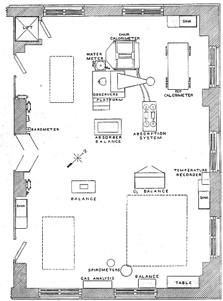
Fig. 2 General view of laboratory room taken near the main door. At the extreme right is the absorber table, and back of it the bed calorimeter. In the immediate foreground is shown the balance for weighing absorbers. A sulphuric acid absorber is suspended on the left hand arm of the balance. At the left is the observer's table and back of it the chair calorimeter with a large balance above for weighing subjects. On the floor, to the left, is the water meter for weighing water used to bring away heat.
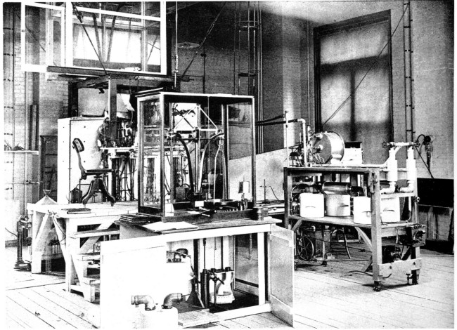
Fig. 3 General view of laboratory taken near the refrigeration room. The observer's table is in the immediate foreground with water balance at the left, and chair calorimeter with balance for weighing man at the extreme left. At the right of the observer's table is the absorption system table, and on the wall in the rear the temperature recorder. At the right is shown the balance for weighing absorbers, and back of that the case surrounding the balance for weighing oxygen.
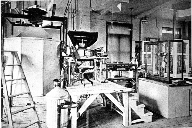
Fig. 4 General view of laboratory taken near the temperature recorder. The bed calorimeter is at the right, the absorber table in the immediate foreground, back of it the chair calorimeter and observer's table, and at the left the balance for weighing absorbers. Near the ceiling are shown the ducts for the cold air used for temperature control.
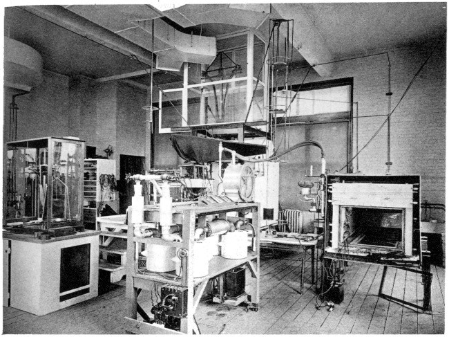
Fig. 5 View of laboratory taken from the entrance of the bed calorimeter, with balance for weighing oxygen cylinders at the left. The structural steel skeleton of the calorimeter for long experiments is at the right and sections of the copper lining are in the rear, resting against the wall.
Another view of the laboratory, taken near the door leading to the refrigeration room, is shown in fig. 3. At the right is seen the balance used for weighing absorbers, and back of it, imperfectly shown, is the case surrounding the balance for weighing oxygen cylinders. On the wall, in the rear, is the recording apparatus for electric resistance thermometers in the water-circuit, a detail of which is shown in fig. 23. In the foreground in the center is seen the observer's table; at the right of this is shown the table for the absorption system, and at the left the chair calorimeter with the balance for weighing subjects above it. The mercury-vapor light, which is used to illuminate the room, is immediately above the balance for weighing absorbers.
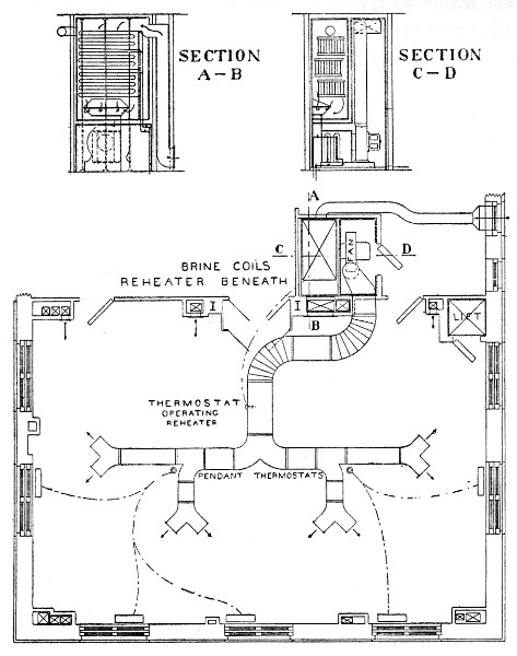
Fig. 6.—Plan of heating and ventilating calorimeter laboratory, showing general plan of circulation of the special cooling system and the position of the thermostats and radiators which they control. The two small diagrams are cross-sections of brine and heating coils.
The bed calorimeter and the absorbing-system table are better shown in fig. 4, a general view of the laboratory taken near the temperature recorder. In the immediate foreground is the table for the absorption system, and back of it are the observer's table and chair calorimeter. At the right, the bed calorimeter with the front removed and the rubber hose connections as carried from the absorber table to the bed calorimeter are shown. At the extreme left is the balance for weighing the absorbers. Above the chair calorimeter can be seen the balance for weighing the subject, and at its right the galvanometer suspended from the ceiling.
The west side of the laboratory at the moment of writing contains the larger proportion of the apparatus. On the east side there exist only the balance for weighing oxygen cylinders and an unfinished[4] large calorimeter, which will be used for experiments of long duration. A view taken near the front end of the bed calorimeter is shown in fig. 5. At the right, the structural skeleton of the large calorimeter is clearly shown. Some of the copper sections to be used in constructing the lining of the calorimeter can be seen against the wall in the rear.
At the left the balance for weighing the oxygen cylinders is shown with its counterpoise. A reserve oxygen cylinder is standing immediately in front of it. A large calorimeter modeled somewhat after the plan of Sondén and Tigerstedt's apparatus in Stockholm and Helsingfors is planned to be built immediately back of the balance for weighing oxygen cylinders.
HEATING AND VENTILATING.
Of special interest in connection with this calorimeter laboratory are the plans for maintaining constant temperature and humidity (fig. 6). The room is heated by five steam radiators (each with about 47 square feet of radiating surface) placed about the outer wall, which are controlled by two pendant thermostats. A certain amount of indirect ventilation is provided, as indicated by the arrows on the inner wall. The room is cooled and the humidity regulated by a system of refrigeration installed in an adjoining room. This apparatus is of particular interest and will be described in detail.
In the small room shown at the south side of the laboratory is placed a powerful electric fan which draws the air from above the floor of the calorimeter laboratory, draws it over brine coils, and sends it out into a large duct suspended on the ceiling of the laboratory. This duct has a number of openings, each of which can be controlled by a valve, and an unlimited supply of cold air can be directed to any portion of the calorimeter room at will. To provide for more continuous operation and for more exact temperature control, a thermostat has been placed in the duct and is so constructed as to operate some reheater coils beneath the brine-coils in the refrigerating room. This thermostat is set at 60° F., and when the temperature of the air in the duct falls below this point, the reheater system is automatically opened or closed. The thermostat can be set at any point desired. Up to the present time it has been unnecessary to utilize this special appliance, as the control by hand regulation has been most satisfactory.
Two vertical sections through the refrigerating coils are shown in fig. 6. Section A-B shows the entrance near the floor of the calorimeter room. The air is drawn down over the coils, passes through the blower, and is forced back again to the top of the calorimeter room into the large duct. If outdoor air is desired, a special duct can be connected with the system so as to furnish outdoor air to the chamber. This has not as yet been used. Section C-D shows the fan and gives a section through the reheater. The brine coils, 400 meters long, are in triplicate. If one set becomes covered with moisture and is somewhat inefficient, this can be shut off and the other two used. When the frozen moisture melts and drops off, the single coil can be used again. It has been found that the system so installed is most readily controlled.
The degree of refrigeration is varied in two ways: (1) the area of brine coils can be increased or decreased by using one, two, or all three of the coils; or (2) the amount of air passing over the cooling pipes may be varied by changing the speed of the blower. In practice substantially all of the regulation is effected by varying the position of the controlling lever on the regulating rheostat. The apparatus functionates perfectly and the calorimeter room can be held at 20° C. day in and day out, whether the temperature outdoors is 40° below or 100° above 0° F.
It can be seen, also, that this system provides a very satisfactory regulation of the humidity, for as the air passes over the brine coils the moisture is in large part frozen out. As yet, no hygrometric study has been made of the air conditions over a long period, but the apparatus is sufficiently efficient to insure thorough electrical insulation and absence of leakage in the intricate electrical connections on the calorimeters.
The calorimeters employ the thermo-electric element with its low potential and a D'Arsonval galvanometer of high sensibility, and in close proximity it is necessary to use the 110-volt current for heating, consequently the highest degree of insulation is necessary to prevent disturbing leakage of current.
The respiration calorimeter laboratory is so large, the number of assistants in the room at any time is (relatively speaking) so small, seldom exceeding ten, and the humidity and temperature are so very thoroughly controlled, that as yet it has been entirely unnecessary to utilize even the relatively small amount of indirect ventilation provided in the original plans.
During the greater part of the winter it is necessary to use only one of the thermostats and the radiators connected with the other can be shut off, since each radiator can be independently closed by the valves on the steam supply and return which go through the floor to the basement. The temperature control of this room is therefore very satisfactory and economical.
It is not necessary here to go into the advantages of temperature control of the working rooms during the summer months. Every one seems to be thoroughly convinced that it is necessary to heat rooms in the winter, but our experience thus far has shown that it is no less important to cool the laboratory and control the temperature and moisture during the summer months, as by this means both the efficiency and endurance of the assistants, to say nothing of the accuracy of the scientific measurements, are very greatly increased. Arduous scientific observations that would be wholly impossible in a room without temperature control can be carried on in this room during the warmest weather.