PART II. NAVAL ORDNANCE.
Reading edition
Austria.
A = Calibre.
B = Over all.
C = Rifled Bore.
D = Powder Chamber.
E = Number of Grooves.
F = Twist of Rifling.
G = Gun, including Breech-block.
H = Breech-block.
I = Preponderance.
Name, Nature, and A Length. E F Weight. I
Classification. B C D G H
In. In. In. In. Calib. Lbs. Lbs. Lbs.
Krupp Pattern Steel Breech-loaders.
28 cm 11 240 170.7 36.41 64 45 60,500 2,266
26 ” 10.24 225 148.4 46.06 32 70 48,400 1,947
24 ” 9.27 206 136 41.7 32 70 34,100 1,408
24 ” 9.27 185 115.3 41.7 32 64.7 32,450 1,419
21 ” 8.24 165 105 37 30 59 19,400 1,078
Wahrendorff Breech-loader.
15 ” 5.87 152 112.4 22.6 36 45 8,800 321 248
Armstrong Muzzle-loaders.
23 ” 9 156 104 20.9 6 45 27,900 255
18 ” 7 130 85.5 18.7 3 35 14,500 394
Cast-Iron Breech-loaders.
15 ” 5.87 121 89.8 16.9 30 63 6,300 178 299
12 ” 4.74 109 84.4 12.4 24 52 3,300 106 273
Bronze Breech-loaders.
9 ” 3.43 81 57.5 16.5 24 45 1,070 55 103
7 ” 2.6 39 23.8 11 18 30 196 49 48.4
Austrian Ordnance—(continued)
A = Carriage.
B = Slide.
C = Height of Axis of Bore above Deck.
D = Steel.
E = Chilled.
F = Common.
Name, Nature, and Classification. Carriages. Projectiles.
A B C Full Weight. Bursting Charge.
D E F D E F
Lbs. Lbs. In. Lbs. Lbs. Lbs. Lbs. Lbs. Lbs.
Krupp Pattern Steel Breech-loaders.
28 cm 29,260 29,260 53 559 574 473 14.3 7.7 25.3
26 ” 6,140 12,617 46 395 354 8.8 20.2
24 ” 4,900 9,845 46 292 263 6.6 3.7 14.9
24 ” 5,814 7,528 45 292 308 263 6.6 3.7 14.9
21 ” 6,194 10,412 45 206 196 172 4.4 3.1 14.9
Wahrendorff Breech-loader.
15 ” 1,878 3,740 39 84.7 69 2.1 5.1
Armstrong Muzzle-loaders.
23 ” 4,188 6,917 44 249 257 5.9 18.5
18 ” 2,956 3,757 45 114 118 1.1 7.9
Cast-iron Breech-loaders.
15 ” 1,047 1,207 39 61 1.9
12 ” 715 32 32 1.1
Bronze Breech-loaders.
9 ” 836 38 14 .4
7 ” 294 21 6.4 .16
G = For Steel and Chilled Shot.
H = For Common Shell.
Name, Nature, and Classification. Powder Charge.
G H
Lbs. Lbs.
Krupp Pattern Steel Breech-loaders.
28 cm 121 121
26 ” 70.4 59.4
24 ” 52.8 44
24 ” 52.8 44
21 ” 37.4 30.8
Wahrendorff Breech-loader.
15 ” 17.6 14.3
Armstrong Muzzle-loaders.
23 ” 50.6 30.8
18 ” 28.6 13.2
Cast-iron Breech-loaders.
15 ” 4.7
12 ” 2.4
Bronze Breech-loaders.
9 ” .9
7 ” .35
Austrian Ordnance—(continued)
A = Ordinary.
B = Saluting.
C = Steel.
D = Chilled.
E = Common.
Name, Nature, and Classification. Powder Charge. Initial Velocity.
A B C D E
Lbs. Lbs. Ft. Ft. Ft.
Krupp Pattern Steel Breech-loaders.
28 cm 1,542 1,673
26 ” 59.4 19.8 1,404 1,378
24 ” 44 15.4 1,420 1,378
24 ” 44 15.4 1,378 1,345 1,329
21 ” 30.8 8.8 1,394 1,253 1,345
Wahrendorff Breech-loader.
15 ” 14.3 4.7 1,608 1,509
Armstrong Muzzle-loaders.
23 ” 30.8 15.4 1,411 1,000
18 ” 13.2 8.8 1,493 1,066
Cast-iron Breech-loaders.
15 ” 4.7 4.7 1,017
12 ” 2.4 2.4 1,000
Bronze Breech-loaders.
9 ” .9 .9 1,469
7 ” .35 .35 977
C = Steel.
D = Chilled.
E = Common.
F = Penetrating Power.
Name, Nature, and Classification. Working Effect. F
C D E
Foot Tons. Foot Tons. Foot Tons. In.
Krupp Pattern Steel Breech-loaders.
28 cm 9,473 14.8
26 ” 5,404 4,666 11.6
24 ” 4,087 3,464 10.6
24 ” 3,838 3,223 3,867 10.25
21 ” 2,781 2,198 2,153 9.3
Wahrendorff Breech-loader.
15 ” 1,379 1,060 7.8
Armstrong Muzzle-loaders.
23 ” 3,429 1,788 9.9
18 ” 1,766 928 8.1
Cast-iron Breech-loaders.
15 ” 438
12 ” 222
Bronze Breech-loaders.
9 ” 209
7 ” 42
The first type of rifled ordnance regularly introduced into the Austrian naval service was the old-type Armstrong muzzle-loader. In addition there are still found a few guns of present obsolete types which never passed the experimental stage. Within the past five years (1876) the Krupp breech-loader has been adopted as the standard pattern, and all guns of a higher calibre than 15-cm. are now of this type, although many complete Armstrong batteries are now found on board ship in the wooden fleet. The boat-guns are of the Krupp type breech-loaders, but are all manufactured of bronze, or what is generally known as Uchatius metal from its method of manufacture.
The Uchatius Construction.
The peculiarity of the Uchatius construction is the method of manipulating the bronze of which the gun is made, by which the metal is given all the advantageous qualities of steel. The body of the gun is cast in a chill mould, by which the cooling is so rapid that the mechanical mixture of tin and copper has no opportunity of separating and forming tin spots as is the case with ordinary bronze castings. After boring the gun, a succession of steel mandrels is driven through the bore, putting the whole casing in a condition of extreme tension on the exterior and compression on the interior, so that the different strata of metal are in proper condition for resisting tangential strains.
Argentine Ordnance.
In the Argentine navy the heavy calibres (used on gun-boats of the Andes class) are Armstrong muzzle-loaders of the modified pattern (see page 195), the medium calibres are divided between old-type Armstrong muzzle-loaders and Krupp breech-loaders. The machine-guns used are Gatlings (see page 308). There is no regular gun factory in the country, the armament being entirely purchased abroad.
Brazilian Ordnance.
The standard ordnance adopted in the Brazilian navy is the Whitworth (see page 218), both muzzle and breech-loaders. Machine-guns are of the Gatling type (see page 308).
Chilian Ordnance.
There is no standard ordnance in the Chilian navy, although the iron-clads are provided with Krupp guns, whilst the wooden fleet is armed with Armstrong muzzle-loaders. It is probable that the Krupp breech-loader will gradually supersede other types. The machine-guns are of the Gatling type.
Chinese Ordnance.
The greater part of the rifled ordnance used in China is of the Armstrong muzzle-loading pattern. Some of their wooden vessels carry batteries of Krupp guns, and others Vavasseurs (see page 219). The Gatling machine-gun has been introduced into this service.
Danish Ordnance.
There are three separate patterns of rifled ordnance found in the Danish navy. The favorite appears to be the Krupp breech-loader, whilst there are many guns of the Finspong pattern (see page 276, “Swedish Ordnance”). The Armstrong muzzle-loader has apparently the numerical superiority.
English Ordnance.
A = Over all.
B = Rifled Bore.
C = Powder Chamber.
D = Number of Grooves.
Name, Nature, and Classification. Length. D
A B C
In. In. In.
17-inch, 100-ton 392 308 55 27
Muzzle-loading, built-up Guns. Woolwich pattern.
Armor-piercing.
16-inch, 80-ton 321 231.5 56.5
12.5-in., 38-ton 230 170.5 27.5 9
12-inch, 35-ton 195 135 27.5 9
12-inch, 25-ton 182.5 127 18 9
11-inch, 25-ton 180 119 26 9
10-inch, 18-ton 180 119 26.5 7
9-inch, 12-ton 156 104 21 6
8-inch, 9-ton 144 99.5 18.5 4
7-inch, 90-cwt 131 95.5 15.5 3
7-inch, 6½-ton 133 95.5 15.5 3
64-pdr., 64-cwt., shell 118 90 7.5 3
Boat.
9-pdr., 8-cwt 72 59.8 3.7 3
9-pdr., 6-cwt 61 49.3 3.7 3
7 pdr., 200-lb., steel 41 34 2 3
64-pdr., 71-cwt., converted 122.7 96.27 7 3
Breech-loaders. Armstrong pattern.
Shell.
7-inch, 82 cwt. 126 83.5 16 76
40-pdr., 32-cwt. 126 92.87 13.5 56
40-pdr., 35-cwt. 127 92.87 13.5 56
20-pdr., 15-cwt 72 43.12 11 44
20-pdr., 18-cwt 72 43.12 11 44
Boat.
9-pdr., 6-cwt. 68 45.5 7 38
6-pdr., 8-cwt. 66 46 7 32
12-pdr., 8-cwt. 78 52.87 8.5 38
E = Twist of Rifling.
F = Weight of Guns.
G = Preponderance.
Name, Nature, and Classification. E F G
Calib. Lbs. Lbs.
17-inch, 100-ton 0/40 229,000 8,960
Muzzle-loading, built-up Guns. Woolwich pattern.
Armor-piercing.
16-inch, 80-ton 179,200
12.5-in., 38-ton 0/35 85,120
12-inch, 35-ton 0/35 78,400 120
12-inch, 25-ton 100/50 56,000 616
11-inch, 25-ton 0/35 56,000 168
10-inch, 18-ton 100/40 40,300 952
9-inch, 12-ton 0/45 26,900 560
8-inch, 9-ton 0/40 20,100 448
7-inch, 90-cwt 35 10,100 560
7-inch, 6½-ton 35 14,500 336
64-pdr., 64-cwt., shell 40 7,160 336
Boat.
9-pdr., 8-cwt 30 896 7
9-pdr., 6-cwt 30 672 29.5
7 pdr., 200-lb., steel 20 200 5
64-pdr., 71-cwt., converted 40 7,950 714
Breech-loaders. Armstrong pattern.
Shell.
7-inch, 82 cwt. 37 9,184 776
40-pdr., 32-cwt. 36.5 3,584 607
40-pdr., 35-cwt. 36.5 3,920 532
20-pdr., 15-cwt. 38 1,680 108
20-pdr., 18-cwt. 38 1,456 164
Boat.
9-pdr., 6-cwt. 38 672 82
6-pdr., 8-cwt. 30 886 55
12-pdr., 8-cwt. 38 896 199
A = Carriages.
B = Slide.
C = Height of Axis of Bore above Deck.
Name, Nature, and Classification. Carriages.
Weight. C
A B
Lbs. Lbs. In.
17-inch, 100-ton Turret
Muzzle-loading, built-up Guns. Woolwich pattern.
Armor-piercing.
16-inch, 80-ton Turret
12.5-in., 38-ton Turret
12-inch, 35-ton 25,000 Turret 45
12-inch, 25-ton 11,800 19,712 60
23,100 Turret
11-inch, 25-ton 21,120 Turret 49
10,700 18,500
10-inch, 18-ton 21,000 Turret 49
8,940 8,680
9-inch, 12-ton 4,800 7,400 44
8-inch, 9-ton 4,780 6,710 44
7-inch, 90-cwt 2,700 3,900 41
7-inch, 6½-ton 3,500 4,700 41
64-pdr., 64-cwt., shell 1,430 2,600 41.5
Boat.
9-pdr., 8-cwt. 532 356 41.5
9-pdr., 6-cwt. 532 336
7-pdr., 200-lb., steel 112 252
64-pdr., 71-cwt., converted 1,600 2,700
Breech-loaders. Armstrong pattern.
Shell.
7-inch, 82-cwt. 1,760 2,796 42.5
40-pdr., 32-cwt. 1,595 1,425 42
40-pdr., 35-cwt. 1,595 1,425 42
20-pdr., 15-cwt. 616 977 29
20-pdr., 13-cwt. 616 977 29
Boat.
9-pdr., 6-cwt. 298 504
6-pdr., 3-cwt. 560
12-pdr., 8-cwt. 364 336
D = Chilled.
E = Common.
F = Shrapnel.
G = Burster for Chilled.
H = Burster for Common.
Name, Nature, and Classification. Projectiles.
Entire Weight. Weight.
D E F G H
Lbs. Lbs. Lbs. Lbs. Lbs.
17-inch, 100-ton 2,000 11.25
Muzzle-loading, built-up Guns. Woolwich pattern.
Armor-piercing.
16-inch, 80-ton 1,700 9.9
12.5-in., 38-ton 800 843 14 43
12-inch, 35-ton 700 615 612 6.5 40
12-inch, 25-ton 600 497 497 6.9 37.7
11-inch, 25-ton 535 536 5.5 29.7
10-inch, 18-ton 400 398 404 4.5 20.25
9-inch, 12-ton 250 250 255 2.5 19
8-inch, 9-ton 180 182 180 2.5 14.5
7-inch, 90-cwt. 115 117 116 8.75
7-inch, 6½-ton 115 117 116 8.75
64-pdr., 64-cwt., shell 64 66 7.2
Boat.
9-pdr., 8-cwt. 9 9.75 .5
9-pdr., 6-cwt. 9 9.75 .5
7-pdr., 200-lb., steel 7 7.5 .4
64-pdr., 71-cwt., converted 64 66 Segment shell. 7.2
Breech-loaders. Armstrong pattern.
Shell.
7-inch, 82-cwt. 90 102 7.6
40-pdr., 32-cwt. 38 40 .25
40-pdr., 35-cwt. 38 40 .25
20-pdr., 15-cwt. 20.5 20 1.2
20-pdr., 13-cwt. 20.5 20 1.2
Boat.
9-pdr., 6-cwt. 9.5 8.5 .4
6-pdr., 3-cwt. 6 5.5
12-pdr., 8-cwt. 11.25 11 .5
A = For Steel and Chilled Shot.
B = For Common Shell.
C = Ordinary Firing.
D = Saluting.
E = Chilled Shot.
F = Common Shell.
Name, Nature, and Classification. Powder Charge. Initial Velocity.
A B C D E F
Lbs. Lbs. Lbs. Lbs. Ft. Ft.
17-inch, 100-ton 440 1,590
Muzzle-loading, built-up Guns. Woolwich pattern.
Armor-piercing.
16-inch, 80-ton 370 1,520
12.5-in., 83-ton 130 1,451
12-inch, 35-ton 110 1,300
12-inch, 25-ton 85 67 55 1,180
11-inch, 25-ton 85 70 60 1,315
10-inch, 18-ton 70 60 44 1,364
9-inch, 12-ton 50 43 30 15 1,420
8-inch, 9-ton 35 30 20 12 1,413
7-inch, 90-cwt 30 22 14 10 1,525
7-inch, 6½-ton 30 22 14 10 1,250
64-pdr., 64-cwt 10 10 6 1,383
Boat.
9-pdr., 8-cwt. 1.75 1.75 1.5 1,380
9-pdr., 6-cwt. 1.5 1.5 1 1,390
7-pdr., 200-lb., steel .75 .75 .25 968
64-pdr., 71-cwt., converted 8 8 6 1,230
Breech-loaders. Armstrong pattern.
Shell.
7-inch, 82 cwt. 11 11 7 1,165
40-pdr., 32-cwt. 5 5 3 1,180
40-pdr., 35-cwt. 5 5 3 1,180
20-pdr., 15-cwt. 2.5 2.5 1.5 1,000
20-pdr., 13-cwt. 2.5 2.5 1.5 1,000
Boat.
9-pdr., 6-cwt. 1.1 1.1 1 1,035
6-pdr., 3-cwt. .75 .75 .7 1,046
12-pdr., 8-cwt. 1.5 1.5 1 1,239
Name, Nature, and Classification. Muzzle Energy. Penetration. (Iron.) Remarks.
Chilled Shot. Common Shell. At 500 Yards. At 1000 Yards.
Foot Tons. Foot Tons. In. In.
17-inch, 100-ton 37,700
Muzzle-loading, built-up Guns. Woolwich pattern.
Armor-piercing.
16-inch, 80-ton 27,213 27.5 26.4
12.5-in., 38-ton 11,676 18.7 17.7 Woolwich groove. Increasing twist.
12-inch, 35-ton 8,200 15.4 14.6
12-inch, 25-ton 7,030 13.9 13.1
11 inch, 25-ton 6,415 13.8 13.1
10-inch, 18-ton 5,160 12.7 12
9-inch, 12-ton 3,496 10.4 9.6
8-inch, 9-ton 2,492 9.8 9.5
7-inch, 90-cwt. 1,855 8.8 8.6 Woolwich groove.
7-inch, 6½-ton 1,246 7.7 7.1 Uniform twist
64-pdr., 64-cwt shell 848 Shunt groove. Uniform twist.
Boat.
9-pdr., 8-cwt. 528 Modern French groove.
9-pdr., 6-cwt. 120 Uniform twist.
7-pdr., 200-lb., steel 45.5 French groove. Uniform twist.
64-pdr., 71-cwt., converted 670 Plain groove. Uniform twist.
Breech-loaders. Armstrong pattern.
Steel.
7-inch, 82-cwt. 847
40-pdr., 32-cwt. 378 Armstrong multigroove. Uniform twist.
40-pdr., 35-cwt. 378
20-pdr., 15-cwt. 142
20-pdr., 13-cwt. 142
Steel.
9-pdr., 6-cwt. 64
6-pdr., 3-cwt. 45.6
12-pdr., 8-cwt. 117
Guns.
The old cast and wrought iron smooth-bore guns are now obsolete, and only found in service at dock-yards for saluting and experiment, and forming the broadside batteries of some of the training ships.
The rifled ordnance consists of the Woolwich muzzle-loader, the Palliser converted muzzle-loader, the Armstrong breech-loader, and the Gatling machine-gun.
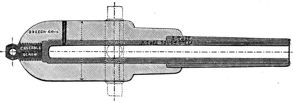
7-inch Mark III.
The Woolwich type is subdivided into marks or patterns of each calibre corresponding to the gradual improvements in manufacture. Mark I. is in most cases the original Armstrong pattern, in which the jacket is composed of a large number of small coils or bands. In the other marks the number of the coils is decreased, whilst each one is increased in size.
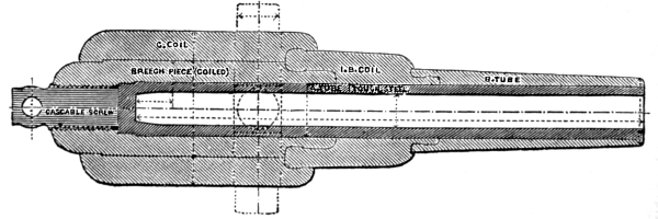
10-inch Mark I.
The Palliser converted type is confined to the 64-pdr. calibre.
The Armstrong breech-loader is no longer manufactured, but there are many guns of this type in service. These breech-loaders were originally of two types, known as the screw and the wedge gun. The latter was designed especially for naval use, but it has been entirely withdrawn from service, leaving only the screw type. It is not improbable that another type of breech-loaders will eventually find its way into service, having a breech-closing arrangement similar to the French type in principle.
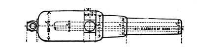
64-pdr.
SECTION OF GROOVE FULL SIZE.
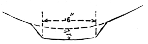
French Groove.
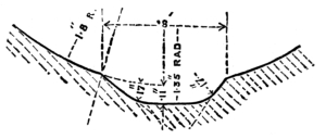
French Modified Groove.
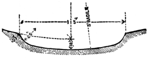
Woolwich Groove.
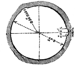
Plain Groove.
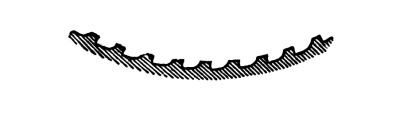
Various systems of grooves will be found in these guns, corresponding to different stages of development. In the 7-pdr. the French groove is used, having sharp angles, the loading side being at a sharper pitch than the driving. In the 9-pdrs. appears the modified French groove, in which the angles are rounded off and the loading side is at right angles to the driving side. In the 64-pdr. converted gun the plain groove is used. This groove is almost rectangular, the driving side being canted but little. In the 64-pdr. of 64 cwt. the shunt groove is used. This is a double groove, one half being deeper than the other, the rear end of the groove having a shunt by which the studs are turned into the shallow half. The 7-inch muzzle-loaders have the Woolwich groove with a uniform twist. This groove is the final modification of the original French groove. The higher calibres up to the 16-inch gun have the Woolwich groove with an increasing twist. The 16-inch calibre will have the plain multigroove, or the groove ordinarily used for expanding projectiles. The breech-loaders have the Armstrong multigroove, a groove which in section is not unlike a saw-tooth.
7-pdr. Steel R. M. L. 200 lbs.
Introduced into service in 1873. Made of a single block of steel, having no swell at the muzzle, but a small dispart patch into which the fore sight screws. Copper vent bouch. The sight is a plain, centre hind sight set at a permanent angle of deflection of 3°. It seats in a hole bored in the metal of the gun, having a simple clamp-screw to hold it in position. Two sight-bars are used with the gun, one graduated to 6° and the other to 12°, the graduations on both being for intervals of 3´. This gun may be distinguished from the 9-pdr. by the slope at the junction of the reinforce and chase, which is gradual.
9-pdr. Wrought Iron R. M. L. 6 and 8 cwt.
Introduced into service in 1871 and 1873. It consists of two parts—a toughened steel tube, and a jacket composed of two single coils and a trunnion-ring welded together. The cascabel is cut out of the solid end of the steel tube, and is recessed to receive the head of the elevating screw, which is fastened to it by a bolt and keep-pin. The 6 cwt. and 8 cwt. guns differ only in length and weight, the latter being 10½ inches longer. The 7-pdr. and the 9-pdr. are of the same calibre, but the same projectiles cannot be used in both, as the twist is different and the studs on the 7-pdr. projectile are much wider than those of the 9-pdr. The arrangement of the sights is the same for both guns. It is easily distinguished by the abrupt step at the forward end of the jacket.

9-pdr.
64-pdr. Wrought Iron R. M. L. 64 cwt.
There are three marks or patterns of this gun. Mark I. was adopted in 1864 to replace the Armstrong wedge breech-loaders. It belongs to the Armstrong type of construction, and consists of a wrought-iron coiled A tube, a forged breech-piece, a trunnion-ring, several outer coiled tubes, and a muzzle-ring. The A tube being bored all the way through, the joints at the bottom of the bore were closed by means of a heavy copper gas-check. The calibre is 6.3 inches, in order to permit firing 32-pdr. round shot from it. The greater part of these guns have been retubed with a steel A tube. In these, the plain groove is found, whilst the iron-tubed ones have the shunt groove. This gun is easily recognizable by its raised trunnion-ring and also by the combination of the stepped breech with the muzzle-ring. Mark II. was adopted in 1866. It is made up of a coiled wrought-iron A tube, double at the chase, a forged breech-piece, a breech-coil composed of a double coil and trunnion-hoop welded together, a coil in front of the trunnions, and a cascabel block. The end of the bore of the A tube is reduced and forms a gomer chamber. These guns may be recognized either by the shunt rifling combined with the Woolwich form of gun or by the letter B marked on the left trunnion. Mark III. is made up of a solid-ended steel A tube, a breech-coil made up of a triple coil, trunnion-ring and coil in front of the trunnions welded together, and a forged cascabel block. These guns are similar in appearance to the 7-inch, but the sea-service guns of this mark have iron A tubes, and may be recognized by the shunt rifling.
64-pdr. R. M. L. 71 cwt. (Converted.)
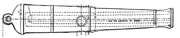
64-pdr. Converted.
Adopted in 1864. This gun is the old cast-iron 8-inch gun, which is bored out and tubed on the Palliser plan. The tube is coiled and double at the rear, and, being through bored, the bottom joints are closed by a screw cup. After insertion the tube is held in place by a muzzle screw-collar and a pin tapped through the casing just forward of the trunnions. The gun is easily recognized from its old-fashioned shape.
7-inch R. M. L. 6½ tons and 90 cwt.
Adopted in 1865. There are three patterns of the 6½-ton guns, the first being of the old Armstrong construction, recognizable by its soda-water bottle shape. The other two marks are of the improved construction. The 90-cwt. gun was adopted in 1874 for use in the armament of unarmored vessels. It is similar to the Mark III. 6½-ton gun, except that it is lighter, the outside being turned down to get the required lightness. These guns are very similar in build and exterior appearance to the 64-pdr.
8-inch R. M. L. 9 Tons.
Introduced in 1866. There are three marks of this gun, similar to the 7-inch patterns. The only way in which the 8-inch can be distinguished from the 7-inch without measuring the diameter of the bore is by the fact of its having four grooves in place of three.
9-inch R. M. L. 12 Tons.
Introduced in 1865. There are five marks of this gun, the first one being of the old Armstrong construction, and the others of the Woolwich developments. The distinctive mark of this calibre is the grooving, there being six grooves.
10-inch R. M. L. 18 Tons.
Introduced in 1868. There are two patterns of this gun, both of the Woolwich design. The distinguishing marks are the nine grooves.
11-inch R. M. L. 25 Tons.
Introduced in 1867. There are two patterns of this calibre, both Woolwich. But few of them are used in the navy. This calibre cannot be distinguished from the 12-inch, except by measurement.
12-inch R. M. L. 25 Tons and 35 Tons.
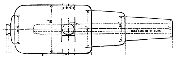
The 25-ton gun was introduced in 1864. There are two patterns, the first built on the old Armstrong pattern, there being but four in service. The second mark is Woolwich. The 35-ton gun was introduced in 1871. There is but one mark of this gun corresponding to the Woolwich.
12-inch Mark I.
12½-inch R. M. L. 38 Tons.
Introduced in 1875. There is but one mark of this calibre, and it exactly resembles the 35-ton 12-inch.
16-inch R. M. L. 80 Tons.
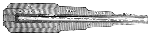
Introduced in 1878. There is but one mark of this calibre. These guns have a chamber one inch greater in diameter than the bore, and the form of rifling is that used with expanding projectiles, being multigroove with shallow grooves. The construction corresponds to the latest development of the Woolwich pattern.
16-inch.
Armstrong Construction.
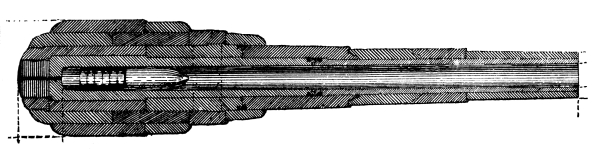
The first type of rifled guns introduced into the English naval service was the Armstrong, for both breech and muzzle loaders. Fabrication of original breech-loader ceased in 1864, but many of this type still remain in service. The original construction of the muzzle-loader was modified in 1864, but the general type and principles were preserved and are still used. The present type of modified Armstrong construction is used by many foreign services, and the 100-ton gun has been introduced in the English service. The modified Armstrong breech-loading system for the 100-ton gun has been adopted in Italy.
The grooves of the breech-loader (original) are saw-toothed in shape, vanishing at the shot-chamber for use with a lead-coated projectile.
Armstrong Groove for Breech-Loader.

Armstrong Shunt Groove for Muzzle-Loaders.
Armstrong 100-ton Gun (Improved Construction).
The grooves of the muzzle-loader (original) are of the shunt or double type, being cut to the full depth for the entire length and one half the width of the groove. The other half of the width is cut on an incline from the muzzle towards the chamber, this half being the driving side. The loading edge of the groove near the bottom is cut at a sharp angle so as to throw the studs of the projectile against the driving edges of the groove, and give it a close bearing. In coming out the studs ride up the incline of the driving side and are pinched, centring the projectile. This groove is now obsolete. The groove of the improved muzzle and breech-loaders is the plain groove.
BREECH-LOADING GUNS (ORIGINAL).
7-inch B. L. R. 82 cwt.
This calibre has been totally withdrawn from service, and has been replaced by the muzzle-loader. The body of the gun consists of an A tube, a breech-piece and B tube, a trunnion-ring and six coils. A vertical slot pierces the gun at the base of the chamber, into which fits a block called the vent-piece. This block is quite light and is easily lifted out or replaced by means of handles. The forward face of the block fits the rear of the chamber, and the escape of gas is prevented by means of a tin-cup gas-check. This vent-piece is held in position when in the gun by a block termed a breech-screw. This block is provided with a full screw-thread, and works longitudinally, the forward end of the block seating against the back of the vent-piece. This breech-screw is provided with a handle for turning, the handle being weighted at the end, and having a lost-motion movement by which the block may be driven close home when screwed up. The vent is bored in the vent-piece, piercing it vertically to the centre, and then turning at right angles. The breech-screw is hollow, the hole being of slightly less diameter than the powder-chamber. When the vent-piece is out, the gun is cleaned and loaded through the breech-screw.
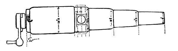
Armstrong Breech-Loader.
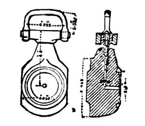
Vent-Piece.
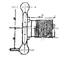
Breech-Screw.
40-pdr. B. L. R. 32 and 35 cwt.
The same general type as the larger calibre. In this and smaller calibres there is no separate gas-check, the joint consisting of two bevelled copper facings, one on the vent-piece and the other in the powder-chamber, which form a close contact and seal the joint by expansion.
20-pdr. B. L. R., 15 and 13 cwt.; 12-pdr. B. L. R., 8 cwt.; 9-pdr. B. L. R., 6 cwt.; 6-pdr. B. L. R., 3 cwt.
Same construction as the 40-pdr., except that the coils are fewer.
Modified Breech-Loaders.
Although these guns are not yet introduced into service, they probably will be. The construction is the same in principle for the body of the gun as in the old breech-loaders, with slight modifications. The breech mechanism is almost identical with the French, the modifications being in the gas-check, which is of the general Broadwell type.
MUZZLE-LOADERS (ORIGINAL).
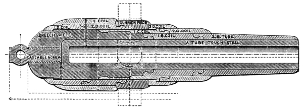
Armstrong 10-inch Muzzle-Loader (Original Construction).
These guns consist of a steel solid-ended tube, reinforced by a number of coils connected by hook-joints. The coils are of wrought-iron bars, rolled into hollow cylinders and the turns welded in order to give a circumferential direction to the grain. Over the breech and powder-chamber a forged breech-piece fits, the grain of the iron running longitudinally. The base of the A tube is supported by a solid wrought-iron piece screwing into the forged breech-piece. A narrow spiral gutter is cut around the A tube throughout its length, and carried out at the cascabel screw-thread. By means of this, in case that the steel tube gets cracked through, the leakage of gas gives warning by blowing out at the breech. Some of these guns (7-inch) have the shunt groove, and the later ones the Woolwich groove.
Modified.
The modified construction consists in abolishing the forged breech-piece, giving the steel tube a greater thickness over the powder-chamber, and decreasing the number of coils, whilst their thickness is increased individually. The guns are also given a greatly increased length of bore, and the powder-chamber is enlarged in diameter to permit the insertion of a heavier charge. Plain grooves.
At present the Elswick Company is engaged in supplying the Italian Government with breech-loading 100-ton guns. The breech-block is of the French type, and arrangements are made for moving the block as well as loading by hydraulic or steam power. The 100-ton gun has no carriage proper, its trunnions resting in heavy blocks on the fixed slide, being connected in rear with hydraulic recoil pistons which are themselves connected in such a manner as to equalize the strain of recoil. The movements of running out and in and loading are all performed by hydraulic power. The vent of the 100-ton gun is axial both in the breech and muzzle loader.
Armstrong Projectiles (see page 209). Armstrong Fuze (see page 211).
Armstrong Breech Mechanism and Rotating Belt.
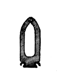
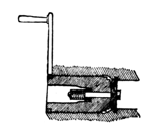
The points of peculiarity of the Armstrong breech mechanism are: 1st. The face of the breech-block is made slightly convex so that the gas-check springs back when the pressure comes on it, throwing the edge outwards, and making a wedged joint. This comes free again the moment that the block is started. 2d. The rear of the shaft holding the gas-check in place is held by a spiral spring, so that in turning the block to lock it the gas-check is not revolved in its seat.
CARRIAGES.
Naval gun carriages and slides, as a rule, are built of plate-iron, although many of the wooden ones are still retained in service for the lighter calibres. The lighter carriages are worked by tackles, and the heavy ones by gearing. Breechings are no longer used with slide carriages, the recoil being checked by friction compressors or hydraulic recoil cylinders and buffers.
Wooden carriages are furnished for all smooth-bores and breech-loading rifles, and for 64-pdr. muzzle-loaders. Iron carriages may be furnished for these guns, but wooden ones are never furnished for others.
The wooden standing carriage is the old-fashioned four-truck one. The wooden rear-chock carriage is similar to what is known elsewhere as the Marsilly. Breechings are rove through holes in these carriages, and are not attached to the guns. The wooden slide-carriages and their slides are of the ordinary old-fashioned type. The compressor for these carriages consists on each bracket of the carriage of two iron plates with hinged pieces on their lower ends. They are suspended on iron bolts passing through the bracket so that their lower ends hang down and overlap the side of the slide. Through the upper ends of the plates and the bracket an iron screw and lever passes, whose motion separates or approaches the pieces, allowing them to release or grip the slide. Some slide-carriages are provided with hydraulic recoil cylinders.
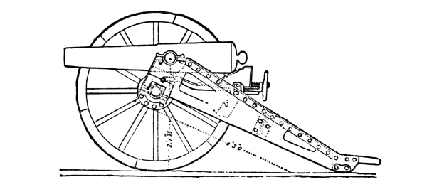
Iron Field-Carriage.
This carriage consists of two ¼-inch plate-iron brackets recessed to receive the axle-tree. These plates are strengthened by angle-irons riveted along the upper edge on the outer side from the trunnion-holes to the point. The brackets are lightened as much as possible by having pieces cut out of them. A front transom of plate-iron, having angle-irons riveted to it each side to connect it with the brackets; a similar transom about half way down the brackets; an iron trail-plate and axle-tree, and wooden wheels. The carriage makes a load for a mule, and the wheels another load. The elevating-gear consists of an iron stool-bed formed in front to hook loosely over a cross-bar, while the rear end, provided with two small studs, rests in racks riveted to the brackets. This is for getting rapid elevations. For fine sighting a sliding quoin is fitted to the stool-bed by clips, and is worked by a hand-wheel. Check-ropes are applied to the trail-eye and lashed to the wheels in firing. The Gatling gun is provided with a curved ratchet projecting down from the bottom of the gun-case, giving elevations by means of a hand-wheel and pinion.
7-pdr. Field-Carriage.
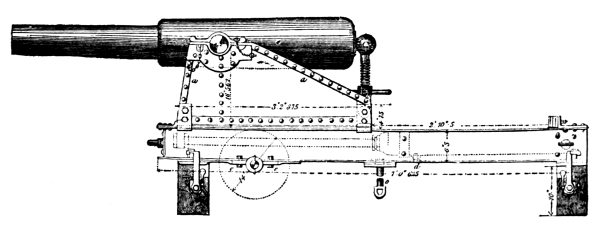
Iron Boat-Carriage.
9-pdr. Boat-Carriage.
The boat-carriage is made up of two ⅝-inch plate brackets, having narrow stiffening pieces along the front and upper edges. The brackets are riveted to a bottom plate by angle-irons on the outer sides, and are connected in front by a transom of plate riveted to angle-irons, and in rear by another transom. It has two outside holding-down clips on each side. The elevating-screw admits of 10° elevation and 2° depression. The slide consists of two sides of girder-iron, 6½ inches deep, and are joined by a connecting plate, three bottom plates, and a rear transom. These bottom plates have metal friction-plates attached beneath them. The centre as well as the front is fitted with a pivot-bolt. The transporting axle bolts beneath the slide. The hydraulic buffer lies upon the centre and rear transoms, to each of which it is secured by a band. This buffer is nothing more than the ordinary type of long cylinder and piston.[3] The cylinder is nearly filled with oil through a hole in the upper rear part. In case it is desired to empty the cylinder, there is a hole for the purpose in the lower forward end. Holes of a certain diameter are bored through the piston, and the recoil is checked in proportion to the resistance of the oil in passing through these holes. The cylinder not being quite full leaves an air-cushion to ease the strain. The piston-rod is secured to the carriage, and a slight vertical play is allowed in its fastenings to prevent the jump of the gun from bending it.
Carriage for Light Upper-Deck Guns.
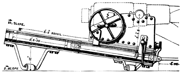
Slide for Light Upper-Deck Guns.
The carriage consists of two ½-inch plate brackets connected by a bottom plate and transom. This carriage has no rollers. It is fitted with the elevating hand-wheel, pinion, and ratchet in use with the heavier calibre.[4] The toothed ratchet bolts to the side of the breech of the gun. The toothed edge of the ratchet gears to a pinion, while the back is supported by a friction-roller attached to the bracket. The pinion being inside the bracket connects with a hand-wheel on the outside, which is held by a friction-brake. The peculiarity of the slide is that it slopes to the front at an angle of 10°. It is provided with a hydraulic recoil buffer (see Boat-Carriage), and also with plate compressors. There are two rubber buffers at the front of the slide to catch the gun in running out, and an in-tackle is fitted underneath the slide. A pivot-flap projects from the front of the slide, the pivot-bolt being close to the gun-port.
Carriage and Slide for 7-inch M. L. R.
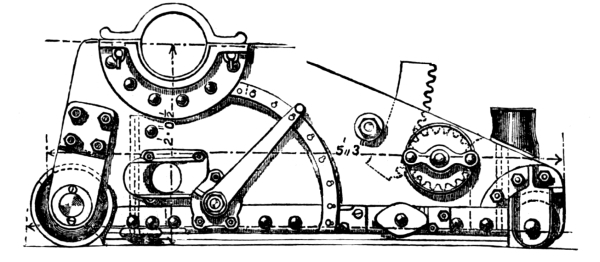
7-inch Carriage.
The carriage is a single-plate one, having two brackets, two transoms, and a bottom plate assembled by angle-irons. The bottom plate is slotted for the Elswick compressor.[5] This compressor is a modification of the American 15-inch one. It is made up of six bars of plate-iron, all of which are movable and which are placed lengthwise in the slide like the wooden balks in the American type. Seven plates hang through the slot in the bottom plate of the carriage, being loosely secured to it. The plates and bars are pressed together by rocking levers worked by screw-shafts, the shafts being worked by levers. The screws on the shafts are of different pitch. That on the right is called the compressing, having a quick pitch; when it is moved it presses the plates against the other lever, which, having a finer-pitched screw, is called the adjusting. The lower end of the adjusting lever is prolonged to form a trip-stop so that the recoil of the gun will throw the lever down automatically.
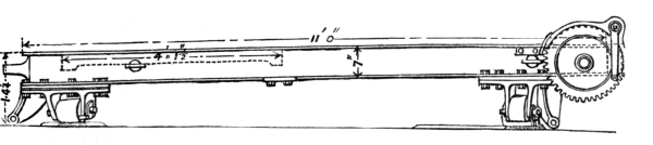
7-inch Slide.
The front rollers of the carriage are permanently in action, whilst the rear ones are on eccentrics. The elevating-gear is the wheel and ratchet. The slide has a slope to the front of 3°. The slide-rollers are on eccentric axles. Attached to the rear of the slide is a simple system of winch-gear for running in and training. This is nothing more than a spur-wheel and windlass revolved by a pinion and crank. In using it, the fall of the in-tackle or training-tackle is caught over the windlass which is turned by the crank. In revolving slides, or slides which shift from one port to another, there is a separate attachment under the forward end, which is nothing more than a centre roller which when thrown into action raises the forward rollers clear of the deck; the after-end of the slide being held by a pivot-bolt, the forward one is swung to a new pivot-centre. This centre roller is thrown into action by gearing. Two ordinary bollard-heads are attached to the rear of the slide, so that the carriage may be held back or veered out in a seaway by turns of the in-tackle falls about them.
Carriage and Slide for 8-inch M. L. R.
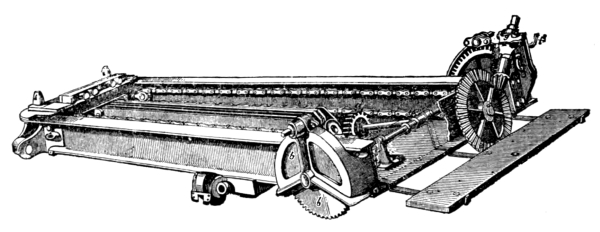
8-inch Slide.
The carriage is similar to the 7-inch, except that instead of being fitted for tackles it is provided with Scott’s nipping-gear and endless chain.[6] The chain is a slide attachment. The nipping-gear consists of a heavy iron stirrup, movable in a vertical direction by means of an eccentric and lever. The chain passes freely through this stirrup when it is down, but on throwing it up the links of the chain are caught in the teeth of a sprocket-plate fastened to the bed-plate of the carriage, so that the movement of the chain carries the carriage with it. The slide is similar to the 7-inch, except that the Scott chain and gearing is used, which also traverses the slide. There are two chains, one at each side of the slide, which are revolved by pinions at either end. At the rear end the pinions are on a heavy axle, which is revolved by a crank and gearing. For training, this gearing is connected to a short shaft, having a pinion at its forward end, which gears in a metal rack on the deck; this shaft may be revolved or fixed at will by means of a pawl-wheel and screw-break, so that in training the slide can be traversed or fixed as desired. When the slide is a shifting one, the same gearing is used to swing the forward end of it around, by means of another pinion which is shipped just in front of the forward end of the slide. The compressor is the Elswick pattern.
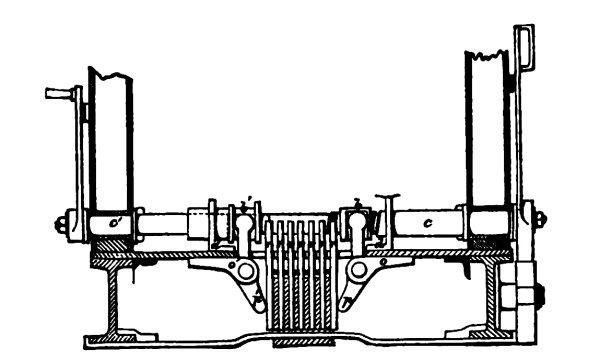
Elswick Compressor.
Carriage and Slide for 9-inch M. L. R.
The broadside 9-inch carriage is the same as the 8-inch; that for ships of the Sultan class differs in several particulars. The carriage is very low, its bottom plate coming well down inside of the slide. It is a double-plate carriage built on a cast-iron frame, the outer plate coming to the top of the slide, whilst the inner one is carried down inside. The rollers are completely hidden in their recesses, the forward ones being permanently in action, whilst the rear ones are on eccentrics. The rear axle between the rollers is bent down so as to give room for the breech of the gun in elevating.
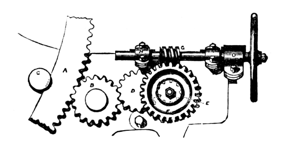
9-inch Elevating-Gear.
The compressor fitted to this carriage is called the bow-compressor. It consists, on each side, of a bow or cramp pivoted at the centre, so that one arm projects inside the carriage through the bracket. A hinged plate is secured to the inner end, while the outer one holds an adjusting-screw which is worked by a hand-wheel, the latter having a pawl to hold it in any desired position. A brass arc near the face of this wheel graduated up to 17° shows the amount of compression. Two projecting pieces are attached to the side of the carriage to support the compressor-plates which hang upon them. These plates are three in number, the two inner ones being tapered, whilst the outer one is square-faced and much heavier. When the carriage is mounted on the slide, these tapering plates lie between the outer side of the slide (the T of which is filled out with wood) and two compressor-bars, which are tapered to correspond with the plates. The adjusting-screw takes against the outer plate, and by turning it the plates and bars are jammed together. The advantage of this compressor is that when once set it is self-acting, going out of action when the carriage is raised on its rear rollers, and coming into action by the weight of gun and carriage when the rollers are down.
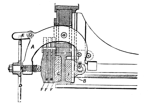
Bow-Compressor.
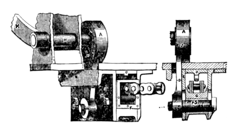
Scott Nipping-Gear.
The Scott nipping-gear is used, but it is single, the chain traversing the middle of the slide. The slide has no peculiarities except its height, which is greater than that of the 8-inch.
Carriage and Slide for 10-inch M. L. R.
The carriages for ships of the Sultan class are the same as those for the 9-inch, except that the rear rollers are thrown in action by means of a hydraulic jack attached to the left bracket, there being a capstan-head arrangement at the other end of the axle for use in case the jack should break down. (For turret-carriage, see turret-carriage of 11-inch.) The slide is similar to that of the 9-inch, except that instead of the bow-compressor two hydraulic recoil cylinders are used, one at each side of the slide.
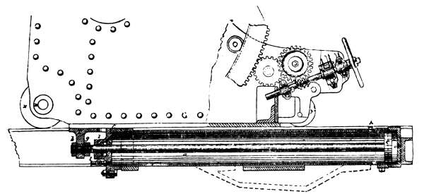
Hydraulic Recoil Compressor.
Carriage and Slide for 11-inch M. L. R.
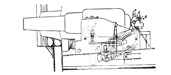
11-inch Small-Port Carriage.
The carriages for ships of the Temeraire or Hotspur class are the same as the 9-inch ones. The turret-carriage is of the muzzle-pivoting type. This carriage presents the peculiarity of having one bracket larger than the other, in order to allow for the circular shape of the turret. The general frame of the carriage is similar in shape to the ordinary type, being double plate on a cast-iron frame, with an interior wrought-iron frame which serves as a guide for the saddle. The gun is supported by the trunnions in a saddle which is nothing more than a massive fork, the leg of which is a hydraulic piston-rod. The arms, containing the trunnion-holes, are supported in the framework of the brackets. The hydraulic cylinder projects through and is secured to the bottom plate of the carriage, and the double-acting pump-brake is attached to a spindle passing through the bracket.
The gun does not rest permanently on the hydraulic, but when at the middle or top of its elevation the saddle-arms are supported by iron blocks, which are put in place through slits in the brackets. When the gun is down the saddle rests on the bottom of its slots. At the low level the gun gets 13° elevation, and at the high level 6° depression. The rear rollers are thrown in action by means of a double-acting hydraulic. The elevating-gear for this gun is different from that of the smaller calibres. Instead of having a curved ratchet attached to the gun, the ratchet in this case is pivoted to the carriage, and a gearing and traveller being clamped to the cascabel of the gun, the breech elevates or depresses up and down the stationary ratchet. This carriage is provided with Scott’s nipping-gear and the bow-compressor, the latter being heavier and double, working on both sides of the slide-plates. These carriages are provided with breechings which pass around a fitting bolted to the inside of the front transom. Additional hydraulic jacks are placed underneath the arms of the saddle for use in case the central one gives out. The slide is similar to the 10-inch, where traversing slides are used. In turrets the slide is a fixture. (See 12-inch slide.)
Carriage and Slide for 12-inch and 12½-inch M. L. R.
The carriage for turrets of the Devastation class is similar in general to that of the 11-inch. The hydraulic lift for the saddle is not a part of the carriage, however, but a part of the ship, there being two rams, one for raising the gun when run out, and one for raising it when run in. The elevating-gear is also different, in having an arrangement for altering the height of the stationary ratchet to correspond with the different levels of the trunnions. The slide is provided with hydraulic recoil cylinders, which also act as the running in and out power. The piston-head has no holes bored in it, but when the gun recoils the oil is driven out of the cylinder, the flow being regulated by a balanced valve. The pump to move the hydraulic is worked by steam, the direction of the movement being controlled by a lever in the turret.
Carriage and Slide for 16-inch M. L. R.
There is no carriage proper for the 16-inch gun, the trunnions resting in saddles on beams fixed in the turret. Hydraulic piston-rods are attached to each saddle, the two cylinders being connected by a pipe to equalize the strain. The breech of the gun rests on a third block which travels in guides. These guides are hinged at the rear, the forward ends resting by means of a cross-head on the piston of a vertical hydraulic cylinder. By means of this the gun is elevated or depressed. The gun is run in or out, elevated, and loaded by hydraulic power.
Loading Arrangements.
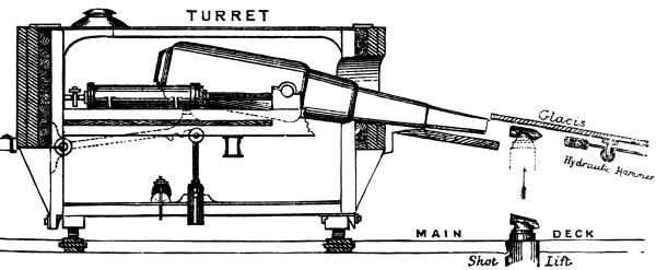
81-ton Gun-Slide and Trunnion Saddles— Hydraulic Loading Arrangements.
With the lighter calibres and broadside guns the usual loading methods are used, the heavy charges and projectiles being transported by means of railways either on deck or under the beams (the projectile in the latter case being slung to a traveller), and raised to the muzzle of the gun by a small davit shipped at the proper point on the slide. With the heavy turret-guns, automatic loading is resorted to. To accomplish this, a hole the size of the bore of the gun is worked in the turret underneath the port. Athwartship openings are left in the turret casing of the main-deck, in front of which are placed a hydraulic lift and the hydraulic extension rammer. The gun being run in, the turret is revoved until the port comes over the station of the rammer. The muzzle is then depressed, and the gun started out until it rests at the loading-hole. The rammer, which is also the sponge, being fixed permanently at the proper angle, is started ahead by a lever and is pushed to the bottom of the bore. On bringing up, a small spring at one side of the rammer-head is pressed, which opens a valve and turns on a stream of water. The rammer being withdrawn, the charge is run up in a hand-car on to the hydraulic lift, by which it is raised to the muzzle. A wad is shipped on the head of the rammer, and the latter, being started ahead, pushes the charge home. Owing to the shape of the rammer-head, the valve-spring cannot be pressed in pushing the charge down, so there is no danger of turning on the water. The position of the rammer-head in the bore is denoted by a simple pointer worked by a string, the other end being attached to the rammer-head. This crude arrangement is frequently out of order, and but little attention was paid to it until its importance was brought forcibly into notice by the double loading and consequent explosion of one of the Thunderer’s guns. One drawback to this system of loading is the care necessary to put the projectile on its car in one exact position, in order that the studs may come opposite their grooves. The car itself must be built at a certain fixed angle to bring the charge exactly in line for loading.
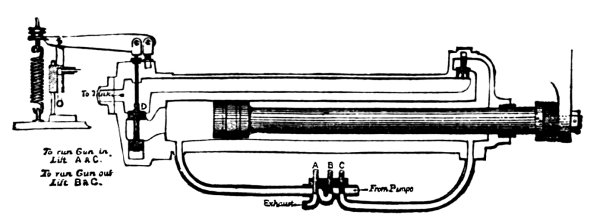
Hydraulic Recoil Press.
GUNPOWDER.
Gunpowder is graduated, according to size of grain and type, into seven distinct classes.
Service Pistol Powder is used for Colts’ and Adams’ pistols and for the bursting charges of shrapnel. It passes through a 44 and rests on a 72 mesh sieve.
Service R. F. G. Powder is used for rifled small-arms, except the Martini-Henry, Gatling guns, and pistols. It passes through a 12 and rests on a 20 mesh sieve. Density, 1.6.
Service R. F. G.² Powder is used for Martini-Henry rifles and Gatling guns. It is of the same size as the R. F. G., but greater density—1.72.
L. G. Powder is used in smooth-bores, and in rifled guns below 7 inches. This powder is being withdrawn as of inferior quality.
R. L. G. Powder is used for full charges in guns of 7 inches and upward where the weight of charge does not exceed forty pounds. It passes through the 4 and rests on the 8 mesh sieve.
P. Powder is used for battering-charges of all rifled guns of 7 inches and above, up to 12½ inches, and for all service charges of forty pounds and upward. The grain is cubical, ⅝ of an inch on a side.
P.² Powder is used with the 12½-inch and upward. This powder is cubical, 1½ inches on a side.
Gunpowder is graduated according to its fitness for use into six classes:
Class I. Service.—All new powder. All returned powder found to be uninjured.
Class II. Blank.—Powder from broken-up cannon-charges too dusty for Class I. Powder from broken-up small-arm ammunition. Service powder found too dusty for use in cartridges.
Class III. Shell.—Powder found too dusty for Class II.
Class IV. Doubtful.—All powder returned into store and waiting examination.
Class V. Condemned for Sale.—Powder too much deteriorated for the higher classes.
Class VI. Condemned for Extraction.—Powder obtained from shells, and powder found to have been too much damaged for any use except for the extraction of the saltpetre.
CARTRIDGES.
Cartridge-bags are made either of serge or of silk cloth.
Serge is used in all smooth-bores and breech-loading rifles, except for the blank cartridges of smooth-bores, which are of silk.
Silk is used for all muzzle-loading rifles.
Cartridges are always filled by weight and not by measure.
All cartridges are both choked and hooped, the number of hoops depending on the length of the cartridge. These hoops are either of twine or braid, according to the size and weight of cartridge and the stiffness required.
All cartridges are marked in black with the nature of the gun for which they are intended, the weight of powder, and the monogram of the station where they were filled.
Cartridges are packed in magazines, in corrugated brass tanks which are either rectangular or pentagonal.
Cartridges for calibres above 8 inches are not transported about the ship’s decks in passing-boxes, but in zinc cylinders with a lock cover.
PROJECTILES.
The projectiles used are shot, shell, shrapnel, and case-shot.
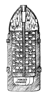
Woolwich Shrapnel.
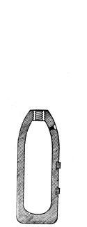
Woolwich Common Shell.
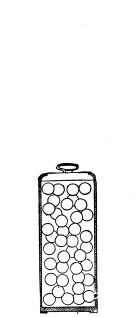
Woolwich Case-Shot.
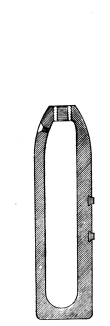
Woolwich Double Shell.
The Palliser chilled shot is used with the muzzle-loading guns of 7 inches and upward. It is of cast-iron, the head as far as the shoulder being cast in a chill, while the rest is in a sand-mould. This shot is never solid, but a space is left large enough to contain a bursting-charge if desirable. By this means a better casting is obtained. With the larger calibres, the cylindrical part of the shot is reduced slightly in diameter to allow for setting up when the projectile first starts. There are four kinds of shells: the segment, common, double, and Palliser. The segment shells are only used with breech-loaders. This shell consists of a thin cast-iron cylindro-conoidal case lined with cast-iron segments built up in layers and leaving a cylindrical powder-chamber in the centre. The base is closed by a cast-iron disc. It is provided with a thin jacket of alloy, which takes in the rifling and gives the twist to the projectile.
The common shell is the ordinary cast-iron projectile. In addition to its fuse-hole it is provided with a loading-hole opening on the shoulder.
The double shell is similar to the common shell, except that it is nearly four calibres long and its chamber is provided with longitudinal strengthening ribs. It is only used in the 7-inch gun.
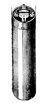
Zinc Passing-Box.
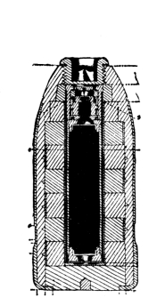
Armstrong Segment Shell.
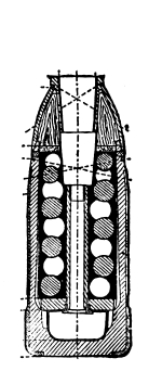
Armstrong Shrapnel.
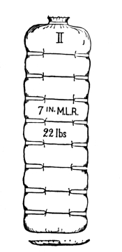
Woolwich Cartridge.
The Palliser shell is similar to the Palliser shot, except that it is slightly longer and has a larger chamber. Fuses are never used with the Palliser shot or shell.
The shrapnel consists of two main parts—the cast-iron body and the wooden head. The body is nearly as thick as that of the common shell, and is scored longitudinally in order to permit it to break up easily. The wooden head is covered with a light sheet-iron case which rivets to the body. The bottom of the chamber is the powder-chamber proper, over the mouth of which rests a wrought-iron disc having a hole in the centre, tapped to take a wrought-iron tube. The upper chamber is filled with lead bullets which are set fast with resin. The fuse screws into a hole in the head, and projects into the wrought-iron tube communicating with the powder-chamber. Both the chamber and the tube are filled with powder.
Case-shot are of the ordinary form. Up to the 7-inch calibre the body is made of tin, beyond that it is of tinned sheet-iron. For the smaller calibres the bottom is of tin, for the larger it is a wrought-iron disc. The top is in all cases tinned iron. The contents of the case are packed in clay and sand, and there is an interior lining made up of three loose-fitting wrought-iron segments.
Shot and shell used with muzzle-loading rifles are now provided with a copper disc attached to the base, called a gas-check. This disc is slightly convex to the rear to enable it to spread and stop the windage on firing. It is attached to the projectile by means of a screw-plug and nut. On firing, it is expanded into the rifling and completely stops the windage. It gains a grip on the base of the shell by means of an undercut rim, whilst radial scores on the base prevent it from gaining an independent rotary motion, and enable it to assist in rotating the projectile.
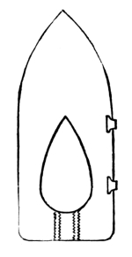
Palliser Shot.
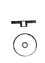
Papier-maché Wad.
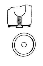
Brass Gas-Check for Projectiles.
All muzzle-loading projectiles are provided with studs for rotation. They are of gun-metal, swedged into countersunk holes, in two rows. The loading side of all grooves is cut back so as to double the width of the groove at the muzzle, in order to facilitate the insertion of the projectile.
Papier-maché wads are used in front of the heavier projectiles to keep them from slipping forward out of place. These wads are very slightly less than the calibre of the gun, and about an inch in thickness. A hole is bored through the centre, large enough to leave a clear space for the fuse. A short papier-maché tube projects from the forward side of the wad, which serves to attach it to the rammer when loading, and hold it vertical while the charge is going home.
Shell-charges for Palliser projectiles are introduced in serge bags to prevent premature explosions.
FUSES.
Both time and percussion fuses are used in the navy. The time-fuses are the Boxer and the Armstrong; the latter used only with breech-loading segment shell. The percussion fuse is the Pettman.
The Boxer time-fuse has a beech-wood body and is conical in shape. The fuse composition is a vertical column in a centre channel which is not bored entirely through the bottom, a base being left to receive the set-back of the column on firing. Two side channels are bored from the bottom nearly to the top, and are filled with mealed powder. Holes are bored from the outside into these channels one tenth of an inch apart, and the composition burns at the rate of one inch in five seconds, so that each hole represents a half-second. The head of the fuse is closed by a safety-cap, which is removed before loading. The time of burning is set by boring through the desired hole into the composition. The bottom hole is always bored through.
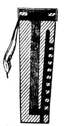
Boxer Time-Fuse.
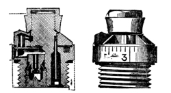
Armstrong Time-Fuse.
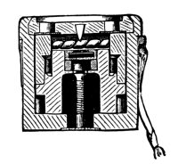
Armstrong Percussion Fuse.
The Armstrong time-fuse is made of gun-metal. A ring of fuse composition similar to that of the old Bormann fuse is pressed in a channel whose outer wall is marked in inches and tenths. This fuse composition is covered by a movable collar which is kept in place by a nut. Attached to this movable collar is a small chamber containing a detonator. When the gun is fired, this detonator ignites the composition at the point at which it is set, and the flame travels around until it meets the magazine, or blowing-chamber, which communicates the flame to the shell-charge.
The Pettman percussion fuse is made up of seven principal parts—the body, top plug, steady plug, detonating ball, cone plug, lead cap, and bottom plug. The top and bottom plugs are set fast; the shock of firing sets back all the other parts, crushing the lead cap over the cone and bottom plugs, which by their shape are all held fast when jammed together. The detonating ball, whose surface is covered with a detonating composition, is carried straight back and prevented from coming in contact with the sides of the chamber by the steady plug. When the projectile strikes, however, the steady plug starts forward and releases the ball, which, coming in contact with the sides of the fuse, explodes the detonating powder and the flame is carried by holes through the lower plugs to the charge.
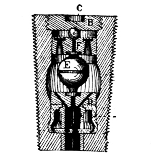
Pettman Percussion Fuse.
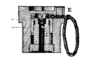
Laboratory Percussion Fuse.
PRIMERS.
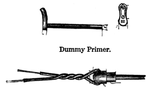
Electrical Primer.
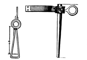
Quill Friction Primer.
Gun-locks are no longer used in the navy. Guns are fired by means of either the friction or the electric tube. The quill friction-tube is used exclusively for the navy. This tube is of two sizes, the short and the long, the latter being used with the heavy calibres. The quill is driven with mealed powder, and a hole is pierced through the centre. The top and bottom are stopped with shellac putty. In the upper part of the tube an iron-wire friction-bar is inserted, having a sprinkling of detonating composition and mealed powder on one side. The top of the tube is strengthened by a thread woolding and a leather loop, which slip over a pin placed forward of the vent.
The naval electric tube consists of a quill body and a xylonite bottom, the quill being of a diameter to slip completely into the vent. Within this quill are insulated terminals of wire connected by a platinum-silver wire bridge surrounded by priming composition. The whole tube goes into the vent, a stop on the insulating wires preventing it from going too far.
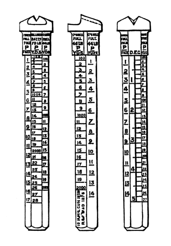
Centre Hind-Sight—Muzzle-Loaders.
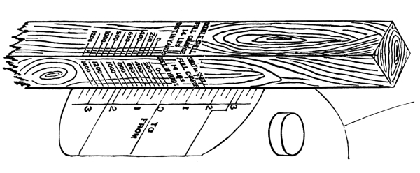
Wood Scale.
SIGHTS.
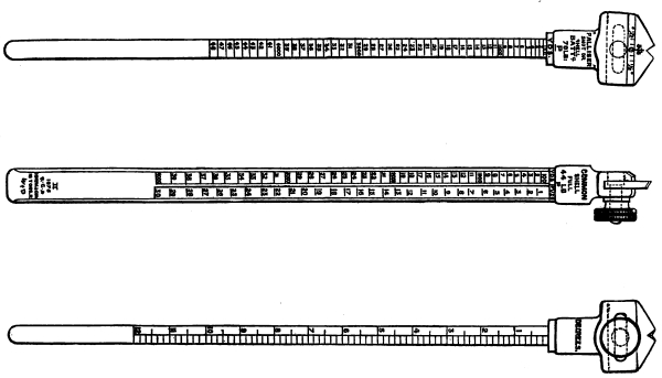
Sliding Leaf Tangent Sight—Muzzle-Loaders.
All muzzle-loading guns, except turret-guns and boat-guns, have six sights—three hind-sights (two tangent and one centre) and three trunnion-sights. Boat-guns have one centre hind and one fore sight, and turret-guns have turret-sights. All guns except boat-guns have wood scales, and all guns in covered batteries, except turret-guns, have graduated arcs on the pivot-circles.
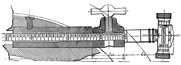
Barrel-Head Tangent-Sight—Breech-Loaders.
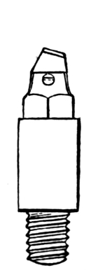
(Screw.)
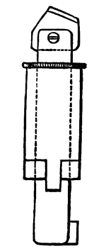
(Drop.)
Fore-Sight.
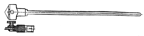
Sliding-Leaf Tangent-Sight—Breech-Loaders.
The tangent-sight is a rectangular steel bar rounded off on two sides, and having a gun-metal head in which slides a gun-metal leaf. The gun-metal leaf slides in a socket, and is provided with a simple clamp-screw. These sights are graduated on the four sides. In general, the forward side is graduated to 10´ from 0 up to 12°. The right side is marked from 100 up to 4000 yards, and for seconds of fuse from 1 to 30—both graduations for common shell with the full charge; the rear side from 100 to 4800 yards for Palliser shot or shell with the battering-charge; the left side from 100 to 4800 yards, and from 1 second to 34 seconds, for common shell with battering-charge.
The centre hind-sight is a hexagonal gun-metal bar with the sliding leaf marked like the tangent-sights, but shorter.
All hind-sights are set at a permanent angle of deflection.
The fore or trunnion sights consist of a pillar and collar of gun-metal, a small steel leaf, and a screw for fixing the leaf. A gun-metal socket is fixed in the gun, and the sight secured in this socket by a double bayonet-joint, so that it may be readily removed or replaced without requiring a special adjustment.
With turret-guns the sights are placed on top of the turret. Each turret is provided with a number of man-holes large enough to admit the head and shoulders. For each man-hole a pair of sights is adjusted, the line of sight being parallel to the axis of the gun. In some turrets, in order to prevent exposure, mirrors are arranged so that these sights may be used by persons in the turret.
The wood scale is a wooden bar used in connection with marks on the rear face of the cascabel. This face is marked from 0 to 3½° for both elevation and depression. The wood scale is a square bar having its four sides marked to yards for different charges. When the gun is placed in position aboard ship, this scale is cut so that its zero and the cascabel zero shall coincide with the guns at level, on an even keel.
The sights for breech-loaders are similar to those of muzzle-loaders, except that what is known as the barrel-headed sliding leaf is used, and there are no centre-sights.
DISTINGUISHING MARKS OF PROJECTILES.
The common shell is known from its carrying a fuse in the point which is cut off for that purpose.
The double shell is known by its disproportion of length to diameter.
The Palliser projectile is known from its sharp point.
The shrapnel is known from the joint which connects the head to the body.
Fragments of a copper disc would denote that Palliser projectiles were used, and a fragment of the head of a Palliser projectile is easily recognizable by the grain of the iron.
PALLISER CONSTRUCTION.
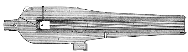
Palliser Converted Gun. (10-inch Rodman Smooth-Bore converted to an 8-inch Rifle.)
The Palliser construction is entirely applied to the conversion of old cast-iron smooth-bore guns into efficient rifles. In this system the bore of the gun is reamed out to a sufficient diameter to permit the insertion of a coiled wrought-iron tube. This tube is made up of a number of short coiled sections end-welded together. The rear of the tube is planed down, and a jacket (coiled with the spirals opposite in direction to the tube) is shrunk on. The breech end of the tube is closed by a wrought-iron disc screwed into place. The surface of the tube is then turned to a snug but not tight fit in the casing or gun, and is inserted, being held in place by a muzzle screw-collar. A screw is tapped through the chase into the tube to keep it from turning. The old vent is bored through and the gun is submitted to a course of proof-firing with full charges, to expand the tube against the wall of the casing, making a snug fit. A spiral slot is cut around the tube from front to rear, and carried through the cascabel as a tell-tale for the escape of gas in case the tube is split or cracked through at a weld. These guns are extraordinarily long-lived, and have been extensively used by the governments of Great Britain and the United States.
Palliser Projectiles. See Pages 208-210.
WHITWORTH CONSTRUCTION.
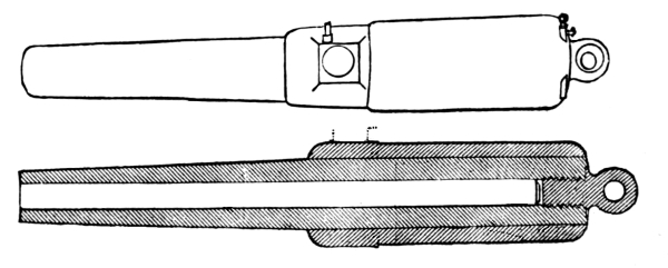
Whitworth Muzzle-Loader.
Whitworth ordnance is used almost exclusively in the Brazilian Navy, and is the regulation type. The Whitworth construction belongs to the all-steel type, and differs in almost every particular from the other types. The guns are both muzzle and breech-loaders. The body of the gun consists of a steel tube reinforced by steel hoops. The tube is cast solid and submitted to a heavy hydraulic pressure while in a molten state, giving the metal as it solidifies a perfectly homogeneous crystallization throughout. This tube is bored completely through, and in the muzzle-loaders the breech end is closed by a steel screw-plug. The hoops are hollow cast and forged on a mandrel, the lengths in the different layers being accurately turned and screwed together; the layers are then put on the gun cold and forced home (from the muzzle end) by hydraulic pressure, the forcing being carefully gauged so as not to crush the metal of the tube.
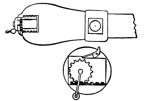
Whitworth Breech-Loader.
The breech-loaders are slotted across the rear face in such a manner that the rear face of the block is entirely exposed, thus saving in length of breech of gun. The breech-block is cubical, and is traversed along the upper and lower surfaces by heavy threads set at an angle with the face of the block. These threads travel in heavy male threads in the slot, the system forming the support for the thrust on the block. Attached to the rear face of the block is a weighted crank which revolves a cogged wheel housed in the block and travelling in a rack in the rear of the lower side of the block-seat. In guns of heavy calibre the system is reversed, the crank and wheel housing in the rear of the gun and the rack in the block. By means of this gearing the block is moved transversely, masking and unmasking the bore, the left end of the block being cut for a loading-hole. A stop on the face of the breech locks the block when home and catches it at the proper point when open.
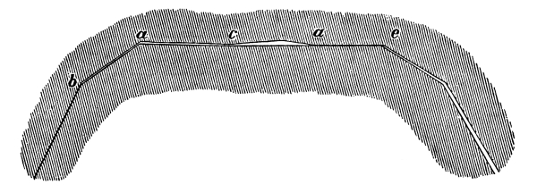
The Whitworth groove is of a peculiar nature, being almost a perfect hexagon, and having an extremely sharp twist of from one turn in 2 feet in the 2-pdr. to one turn in 13 feet in the 9-inch.
The projectiles are cut to fit the grooves, the armor-punching ones being of compressed steel.
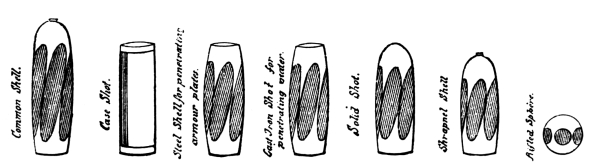
Whitworth Projectiles.
THE VAVASSEUR CONSTRUCTION.
Vavasseur ordnance is used considerably in China, and has found some use in other quarters of the world. The gun belongs to the steel type. It consists of a mild-steel oil-tempered tube, reinforced by steel hoops, the hoops being narrow and numerous and shrunk on. The trunnion-hoop is of wrought iron. The gun has, properly speaking, ribs instead of grooves, the grooves being cut in the projectiles. The twist is a constant one.
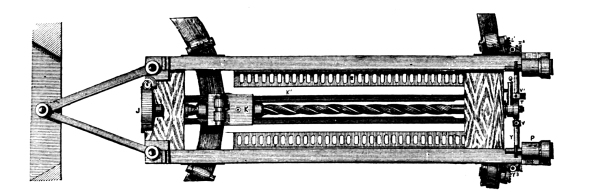
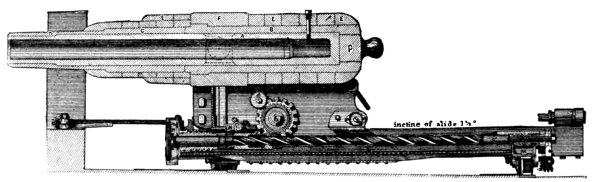
Vavasseur Gun and Carriage.
The gun-carriage possesses a peculiar recoil arrangement, consisting of a heavy screw-shaft traversing the middle of the slide and carrying at its forward end a wrought-iron friction-wheel with a metal strap worked by a lever, by which any desired amount of friction may be applied. Attached to the carriage is a sleeve or clutch grasping the screw-shaft. When the gun recoils, the motion of the sleeve along the shaft causes the latter to revolve, the friction being regulated by the friction-band. For running in and out a large cog-wheel is fixed to the inside of each carriage-bracket, the cogs taking in racks along the sides of the slide. In starting the gun out, the motion of starting slacks the friction-band on the screw-shaft, allowing the gun to run freely; for controlling the motion in a seaway, a small friction-brake on the rear of the slide is used. The carriage is mounted on eccentric rollers, and the movement of throwing them out of or into action ungears or gears the running-out cranks outside of the brackets, so that in recoiling the cranks are not thrown around. The chamber of the Vavasseur gun, as originally constructed, is smaller than the bore, being in this a reversal of the present accepted true principle, and limiting the guns to small charges and low velocities.
French Ordnance.
A = Over all.
B = Bore.
C = Number of Grooves.
Name, Nature, and Classification. Calibre. Length. C
A B
In. In. In.
French pattern, cast-iron, steel-lined Breech-loaders.
Model of 1870.
32 cm. 12.6 264 244 32
27 ” 10.8 212 194 28
24 ” 9.46 195 179 24
19 ” 7.64 164 151 20
16 ” 6.49 146 135 16
14 ” 5.46 123 115 14
Model of 1864-67.
27 ” 10.8 184 167 5
24 ” 9.46 180 165 5
19 ” 7.64 150 138 5
16 ” 6.49 133 124 3
14 ” 5.46 81 73.6 3
Bronze Muzzle-loaders
12 cm 4.78 81.4 71.5 6
4 ” 3.41 37.8 31.7 6
Hotchkiss Machine-gun. 1.46 51.2 29.1
Model of 1858-60 Muzzle-loaders
22 cm
16 ”
14 ”
D = Twist of Rifling.
E = Gun, including Breech-block.
F = Breech-block.
G = Preponderance.
Name, Nature, and Classification. D Weight. G
E F
Cal. Lbs. Lbs. Lbs.
French pattern, cast-iron, steel-lined Breech-loaders.
Model of 1870.
32 cm. 0/45 85,800 1,540 396
27 ” 0/45 51,040 1,100 88
24 ” 0/45 34,400 726 88
19 ” 0/45 17,500 352 88
16 ” 0/30 12,000 103
14 ” 0/30 5,900 176 103
Model of 1864-67.
27 ” 0/30 45,100 704
24 ” 0/30 31,900 567
19 ” 0/30 17,610 295
16 ” 0/30 11,000 191 330
14 ” 0/30 4,100 103 165
Bronze Muzzle-loaders.
12 cm. 1,360 176
4 ” 220 33
Hotchkiss Machine-gun. 440
Model of 1858-60 Muzzle-loaders.
16 ”
14 ”
A = Carriage.
B = Slide.
C = Steel.
D = Chilled.
E = Common.
F = Canister.
G = Bursting Charge Common Shell.
Name, Nature, and Classification. Carriage. Projectiles.
Weight. Complete Weight. Weight.
A B C D E F G
Lbs. Lbs. Lbs. Lbs. Lbs. Lbs. Lbs.
French pattern, cast-iron, steel-lined Breech-loaders.
Model of 1870.
32 cm. 770 770 630 37.4
27 ” 10,230 12,960 475 475 396 317 24
24 ” 7,304 8,140 317 317 264 220 17
5,720
19 ” 4,664 11,550 165 165 137.5 114 7
4,400 3,410
16 ” 3,520 9,460 99 99 84 69
14 ” 2,085> 1,287 46 41 2.4
Model of 1864-67.
27 ” 10,230 12,980 475 317 321 14.6
24 ” 5,720 8,140 817 220 211 10.3
220
19 ” 4,400 3,410 165 115 105 4.8
16 ” 3,520 9,460 99 69 66 3
2,639 1,260
14 ” 1,540 1,100 41 27 2.1
39.6
Bronze Muzzle-loaders.
12 cm. 1,023 25 24.6 1.1
385
4 ” 352 231 10 10 .17
319
Hotchkiss Machine-gun.
Model of 1858-60 Muzzle-loaders.
22 cm.
16 ”
14 ”
A = Steel and Chilled Shot.
B = Common Shell.
C = Ordinary.
D = Saluting.
E = Steel.
F = Chilled.
G = Common.
Name, Nature, and Classification. Powder Charge. Initial Velocity.
A B C D E F G
Lbs. Lbs. Lbs. Lbs. Feet. Feet. Feet.
French pattern, cast-iron, steel-lined Breech-loaders.
Model of 1870.
32 cm. 132 132 1,394 1,394 1,496
27 ” 92.4 92.4 52.8 19.8 1,417 1,417 1,542
24 ” 61.6 61.6 35.2 13.2 1,443 1,443 1,555
19 ” 33 33 17.6 7.7 1,456 1,456 1,726
16 ” 20.9 20.9 1,575 1,575 1,660
14 ” 9 9 3.3 1,493
Model of 1864-67.
27 ” 79.2 52.8 52.8 19.8 1,086 1,188
24 ” 52.8 35.2 35.2 13.2 1,115 1,188
19 ” 27.5 17.6 17.6 7.7 1,128 1,168
16 ” 16.5 11 11 5.5 1,132 1,197
14 ” 4.4 4.4 4.4 1,053
Bronze Muzzle-loaders.
12 cm. 2.2 2.2 2.2 1,007
4 ” .66 .66 .66 738
Hotchkiss Machine-gun. .18 1,318
Model of 1858-60 Muzzle-loaders.
22 cm.
16 ”
14 ”
Name, Nature, and Classification. Muzzle Energy Penetration.
Steel. Chilled. Common. Steel. Chilled.
Ft. Tons. Ft. Tons. Ft. Tons. In. In.
French pattern, cast-iron, steel-lined Breech-loaders.
Model of 1870.
32 cm. 10,390 10,390 9,730 14.5 14.5
27 ” 6,596 6,596 6,506 12.5 12.5
24 ” 4,561 4,561 4,414 11.1 11.1
19 ” 2,330 2,330 1,828 9 9
16 ” 1,698 1,698 1,598 8.2 8.2
14 ” 712
Model of 1864-67.
27 ” 3,871 3,088 9.6
24 ” 2,821 2,144 8.75
19 ” 1,451 1,081 7.0
16 ” 876 687 5.87
14 ” 314
Bronze Muzzle-loaders.
12 cm. 176
4 ” 39 .94
Hotchkiss Machine-gun. .94
Model of 1858-60 Muzzle-loaders.
22 cm.
16 ”
14 ”
GUNS.
Smooth-bore guns are entirely obsolete, except for saluting purposes at dock-yards.
The rifled ordnance consists of the cast-iron breech-loader, model 1870, the cast-iron breech-loader, model 1864-67, the cast-iron muzzle-loader, model 1858-60, the bronze muzzle-loader, the mitrailleuse, and the Hotchkiss machine-gun. A new all-steel pattern is being introduced into the service, whose attachments are quite similar to the model of 1870.
The two models of breech-loaders differ radically in the style of rifling, and although the breech mechanism is the same in principle in both types, it is quite different in detail.
Breech-Loader, Model 1870.
Guns of this type consist of a cast-iron body strengthened by a steel tube and steel hoops. The steel tube, which is about one quarter of a calibre in thickness, is inserted into the bore from the rear, and is set fast by a heavy male screw-thread worked at its rear end. It extends a short distance forward of the trunnions. The steel hoops are shrunk on over the cast-iron body, and cover all that part occupied by the tube. For the 14-cm. calibre there is but one row of hoops; for the higher calibres two rows breaking joints. The trunnions form a part of the hoop next to the forward one. In all calibres above 16-cm. this trunnion-hoop is thicker than the others, and forms a salient on the surface of the gun.
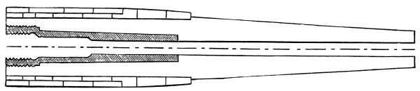
27-cm. French Gun, Model 1870.
The bore is rifled on the multigroove system, with an increasing twist of from 0° at the breech to 4° at the muzzle, the direction of the twist being from right to left (contrary to the invariable rule in other countries). The chamber proper is divided into four parts: the shot-chamber, the powder-chamber, the gas-check seat, and the breech-block seat.
The shot-chamber is conical in shape, small end forward, the rifling vanishing at this point in an easy slope. The diameter of this end is the same as that of the bore measured across the grooves. The rear end is joined to the powder-chamber by a second small cone, against which the rear ring of the projectile takes when home.
The powder-chamber is cylindrical, and of a diameter slightly greater than that of the bore.
The gas-check seat is of considerably greater diameter than the powder-chamber. It is conical in shape, small end forward.
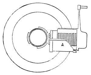
Breech-Block (Gun open).
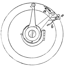
Breech-Block (Gun closed).
The breech-block seat is cylindrical, having a heavy screw-thread around its wall, which is cut into three equal sectors, leaving three blanks of the same width. One of these blanks comes at the bottom of the seat, in order to allow the breech-block to slide back and forth.
The breech mechanism consists of two main parts, the block and the console or bracket, which is hinged to the face of the breech and holds the block when it is withdrawn from its seat.
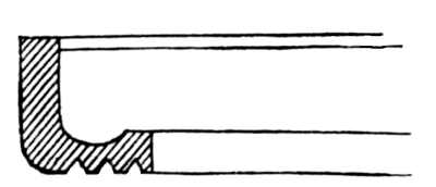
Gas-Check (1871).
The breech-block is a steel cylinder having heavy screw-sectors about its surface to correspond with those in the seat. The last turn of screw-thread is left entire in order to relieve the shock of closing the breech. The forward face is made movable in order that when it becomes worn and scored by the action of the powder-gas it may be changed. This face is a steel disc which sets flat against the face of the block, and is of the same diameter. It seats in the face of the block by means of a smaller cylinder or trunnion, and projecting from the rear of this trunnion is a steel rod, which passes completely through the axis of the block and carries the vent. In order to prevent the disc from having any independent motion, a small tenon on its rear face enters a socket in the face of the block. The disc is keyed fast by a small pin which is screwed radially through the block near the middle, the end of the pin taking in a score cut in the vent-rod. A small catch, projecting from the rear lower side of the block, holds the console in place when the breech is closed. The rear face of the block is provided with two parallel handles screwed to it, to assist in moving it, and a long crank-handle between them for revolving the block. At the end of this crank-handle there is a slight projection made to receive the blows of any instrument that may be used to drive the block around when it works stiffly. Along the two lower blanks of the block slots are cut, in which traverse small projections of the console to hold the block steady. About the middle of the lower screw-sector a small hole is cut into which a small stop springs when the block is withdrawn to its limit on the console. The vent is provided with a copper bush at its forward end and a steel one at its rear.
The console is semi-cylindrical, and is hinged to the face of the breech so that when the breech-block is withdrawn it may be swung to the right and unmask the bore. It is provided with a spring stop and two small projections taking in the block, which limit the movement of the latter and hold it steady when resting on the console.
Two small pins, screwed into the face of the breech, limit the arc of movement of the crank-handle, one at the vertical point and the other 60° to the right.
A small stop attached to the face of the breech holds the crank-handle fast when the breech is closed. This stop allows the handle to pass in closing, but must be raised by hand in opening.
The gas-check is of copper, and is a fixture in its seat. It is a ring in reality, the centre being cut out to permit the passage of the charge through it in loading; the edge is turned up, forming a cup, the outer part being conical to fit the seat. The bend of the rim is quite thick, and a gutter is cut around it in order to make the powder-gas seal the joint properly. The bottom of this ring is provided with three concentric grooves to break the force of the gas that may escape through the joints. When the breech is closed the face of the block presses directly on the gas-check, and a copper ring is countersunk in the face of the block which forms the contact with the check. This ring has grooves to correspond with the grooves on the back of the gas-check.
The vent is horizontal, and is situated in the axis of the breech-block. Its outer end is formed in double-cone shape (throughout the steel bush), the small ends of the cone being joined. Percussion primers are used in connection with a spring gun-lock. (See Primers.)
Breech-Loader, Model 1864-67.
These guns are hooped like the model of 1870, but are not tubed.
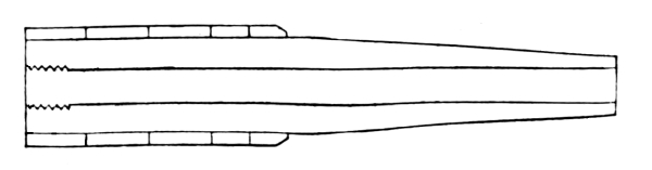
14-cm. French Gun.
The vent is pierced vertically near the bottom of the powder-chamber, instead of being in the breech-block.
The grooves are of the pattern known as the “basket-handle,” for mechanical fit projectiles (see French Groove, English Ordnance), having an increasing twist of from 0° to 6°. The 14-cm. and 16-cm. guns have three grooves, the others five. The width of the grooves is the same throughout the length of the bore, being cut back on the loading side near the powder-chamber to facilitate loading. The depth of the groove, however, diminishes towards the muzzle in order to pinch the studs and steady the projectile. At the powder-chamber and running forward for a short distance in the centre of each band is a supplementary groove, in which travel the rear studs of the projectiles, which are made so small as to easily sheer off. These secondary grooves prevent the projectile from being pushed too far into the bore. With the 19-cm. gun, the supplementary groove is made by cutting back the loading side of the regular groove. There is no shot-chamber proper.
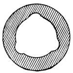
Groove (1864).
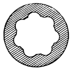
Groove (1871).
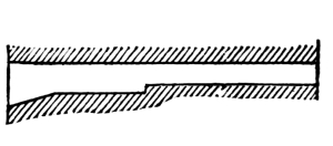
Rear end of Groove (1864), showing Stop for Projectile.
The powder-chamber is cylindrical, of the same diameter as that of the bore across the grooves. The bottom groove is produced through the powder-chamber, to serve as a directing groove for the projectile in loading.
In rear of the powder-chamber there are two gas-check seats, conical in shape, with the small diameter forward. The rear and larger one is intended for service in case of accident to the other.
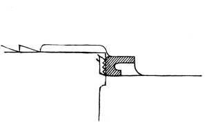
Gas-Check (1864).
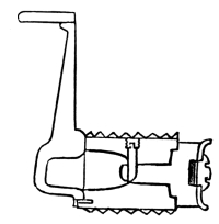
Breech-Block (Section).
The breech-plug seat is similar to the model 1870.
The breech-closing mechanism consists of two main parts like that of the model 1870, the breech-plug and the console or bracket.
The breech-plug differs from the model 1870 in being lighter, by having the interior cut away as much as possible consistent with strength. It has two movable faces or discs to correspond with the two gas-check seats. These discs are secured to the face of the plug in a similar manner to the model 1870, except that the disc in this case is allowed to revolve freely. The gas-check is carried on the face of the disc instead of being a fixture of the gun.
It is quite similar to the model 1870, except that the hole in the centre is smaller and serves to secure it to the face of the disc. The centre of the disc being slightly raised carries two ears which receive the inner edge of the gas-check and centre it. Over these a solid-headed nut screws, which fixes the gas-check and makes a tight joint. The gas-check is made of steel.
The console is similar to the model 1870.
Muzzle-Loader, Model 1858-60.
These guns are hooped, but have no tubes. The trunnions are cast with the body of the gun, the hoops not coming so far forward. The vent is vertical near the bottom of the powder-chamber, like the model 1864.
The grooves are of the “basket-handle” type, three in number, with an increasing twist of from 0° to 6°. These grooves, near the chamber, are cut back and prolonged to form seats for the rear studs.
All guns of this model are converted from old smooth-bores.
Bronze Muzzle-Loader.
These guns are of the ordinary bronze type. The 23-pdr. (canon de 12) has six common grooves having a regular twist from left to right. The bottom groove is narrowed on the loading side near the powder-chamber in order to force the studs into close contact with the driving side. The 8-pdr. (canon de 4) has six grooves with a regular twist similar to the 23-pdr.
The vent is pierced vertically near the bottom of the powder-chamber.
The Mitrailleuse.
The exterior of the mitrailleuse has the appearance of a bronze cannon. This case encloses 25 rifled tubes brazed together. The rear part of the cannon presents a vertical cavity, very large and nearly rectangular in shape. This cavity is called the cage, and is intended to receive the breech-block and firing mechanism. The breech-block is a cubical block containing prolongations of the 25 barrels which serve as chambers for the cartridges. When loaded, this block drops into the forward part of the cage. The lock mechanism is a box containing 25 firing-pins, arranged with guides and springs on the ordinary system. This box is movable longitudinally by the motion of a breech-screw, which also sets up the breech-block when in place. The motion forward of this box retracts the firing-pins, which are then held until released in rapid succession by a turn of the crank. After firing, the breech-screw is backed, the block taken out and a loaded one is put in its place, the screw is set up retracting the locks, and the piece is ready for firing again.
Hotchkiss Machine-Gun.
(See United States Ordnance.) This gun is an American invention, but was first introduced into the French Navy.
CARRIAGES.
Gun-carriages in the French Navy are classified as follows:
Slide-carriages for heavy broadside-guns.
Turret-carriages and revolving-slide carriages for heavy guns.
Directing-bar carriages for broadside-guns.
Four-truck and rear-chock carriages for broadside-guns.
Gun-boat carriages for bronze guns.
Boat-carriages for bronze guns.
Mountain carriages for bronze guns.
Mitrailleuse saddle or fork for machine-guns.
Slide-Carriage for 27-cm. and 24-cm. Guns.
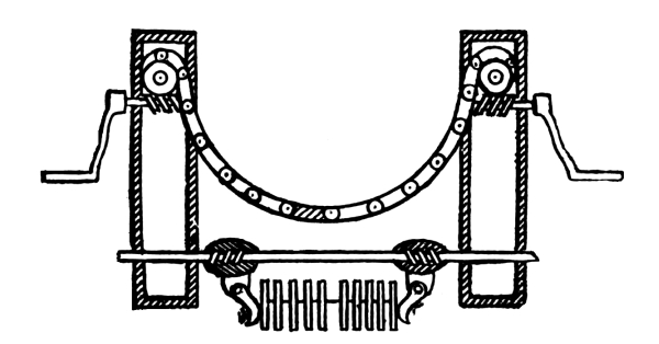
Elevating-Gear and Compressor, 24-cm. Gun.
The rails of the slide are of heavy double T iron, connected by T and plate iron transoms. The slide rests on a pair of conical rollers, with concentric axles forward and a double pair of rear rollers (concentric) at the rear. The forward pair of the rear rollers and the front rollers travel on smooth tracks, while the rear pair of rollers are pinions working in a rack on deck. The slide is traversed by tackles, except in fine pointing, when levers are shipped on the rear rollers and the fine traversing is done by heaving on them. A pawl working on the rear rollers secures the slide in any desired position. The recoil is checked by friction compressors. There are eight iron compressor-bars on each side of the slide, just inside of the rails, resting on the front and rear transoms. On top of the front transom is a heavy iron dumb-sheave, which receives the bight of a rope breeching. The carriage is of the ordinary form of double plate, mounted on rollers, the forward pair being in permanent action and the rear pair on eccentric axles. Tackles are used for running out and in. The compressor-plates are nine in number on each side, suspended on an axle. The outer plates are heavier than the others. The ones next to the brackets are backed by steel disc-springs. Rocking levers working in screw-threads on the axle press against the inner plates. The levers are worked by a ratchet-lever on the exterior right side, this lever being provided with a trip for throwing it down automatically in firing. Railway buffers are placed at the rear of the slide to act in case of over-recoil. The elevating-gear consists of a flat-linked chain passing underneath and supporting the breech of the gun. The ends of the chain wind about axles in the carriage-brackets, the axles being revolved by endless-screw gearing. Levers for turning this gearing ship outside the brackets. In elevating or depressing, it is necessary to turn the gearing alike on both sides in order to keep the centre link, which is marked, in its place under the breech. In elevating, the gearing must be worked slowly in order to allow the breech to follow down by its preponderance. With the 24-cm. gun, the compressor-plates, 12 in number, are all in the centre instead of being at the sides.
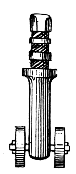
Slide-Truck for 19-cm. Gun.
Slide-Carriage for 19-cm. Gun.
The fixtures for the slide and carriage differ in several particulars from the heavier ones. The slide travels on four pairs of rollers, the rear rollers of the rear pairs being cogged for fine pointing as in the heavier ones. The slide rests on iron pillars with screw-threads at the upper extremities, the lower ones resting on the axles between the rollers, forming a pair. The threaded top has a capstan-head, so that, by turning, the front or rear of the slide may be elevated or depressed. These rollers are also arranged for transporting the slide from port to port. For this they may be turned to run in the desired direction, similar to the principle of chair-rollers (casters). Clamps are provided to hold them in the desired position.
The carriage has only one in-tackle. The rocking-lever compressor is changed to the ordinary bow-compressor. (See English Ordnance, Compressor for wooden-slide carriages.)
Turret-Carriage and Slide for Heavy Guns.[7]
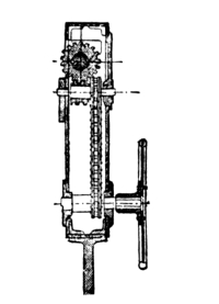
Additional Gearing for Elevating-Gear of Turret-Carriage.
The turret-slide, instead of being provided with rollers for traversing, is mounted on a centre-pivoting turn-table. The turret itself is fixed, the gun firing over it “en barbette.” The turn-table is mounted on sixteen conical rollers, and is revolved by means of a fixed rack, to which gears a pinion worked by a crank attachment on the slide. This attachment consists of a horizontal axle revolving in bearings through the rear of the slide-plates, having a crank at each end and a chain-wheel in the middle. An endless chain transmits the motion to gearing at the forward end of the slide, which connects with the rack on the floor of the turret. A locking arrangement holds the turn-table in the desired direction. The slide resting on its supports rises to a much greater height than with broadside-carriages, and is provided with a short stairway from the turn-table to the slide-top. The carriage is similar to the ones heretofore described, except that extra gearing is applied to the elevating apparatus to enable it to be reached by the men standing on the turn-table. Chain-gear similar to Scott’s in and out gear is used with the carriage. Instead of a movable stirrup used to catch the chain, the upper part passes through a slit in the rear transom of the carriage, so that when the rear trucks are thrown in action teeth in it catch the chain. The same style of compressor is used as is found with the 24-cm. carriage previously described, except for the 19 cm. gun, which has the ordinary cramp-compressor.
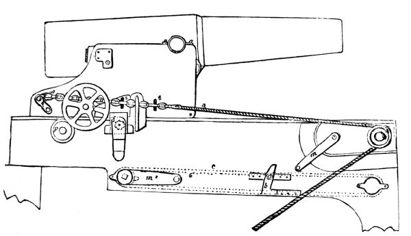
Barbette Turret-Carriage.
Revolving-Slide Carriage.
The slide is a centre-pivot resting on a circular track and on four rollers. It is traversed by a crank revolving gearing which works in a circular rack around the outside of the roller-circle. The carriage is similar to the ordinary type, except that it is much higher, in order to allow a greater angle of depression to the gun. Instead of in and out tackles, a runner is used which passes over a windlass fixed on the rear slide-transom. This runner throws the rear trucks in action, and then, according to its lead, runs the gun in or out. The elevating-gear for the 16-cm. gun consists of a heavy cross-bar underneath the breech, having sleeves at the extremities which clasp heavy upright screws. By revolving these screws, the bar is carried up or down. The elevating-gear for the 14-cm. gun is the old-fashioned telescopic elevating-screw.
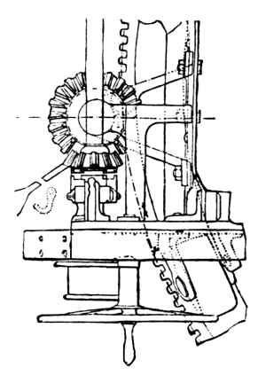
Training-Gear for Centre-Pivot.
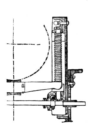
Elevating-Gear for Centre-Pivot Carriage.
Directing-Bar Carriage.
The carriage proper is of the ordinary rear-chock or Marsilly type, which when run out for firing is lifted from the deck on a slide or chariot, so that it may be easily and quickly trained. The chariot consists of a broad, short front-piece, mounted on two rollers; projecting forward from it is a pivot-flap which secures by a pivot-bolt just underneath the port, the rollers being canted for traversing about the pivot. Projecting to the rear from this front-piece is a tongue made of T iron, which is supported at its rear end on two trucks which are canted like the forward ones for traversing. When the carriage is run in, its rear end comes flush with the end of this tongue, and the forward trucks rest on the deck. In running out, however, two small rollers on the axle, inside of the brackets, catch on and mount two inclined planes which slope back from the top rear of the chariot, thus lifting the carriage completely from the deck. A breeching is used with this carriage, its bight going around a B block on the front of the chariot. There is also a friction compressor at the rear of the brackets, the compressor plates taking against the sides of the T iron, which are filled out with wood for that purpose. The forward edge of the B block serves as a hurter in running out. In all other respects the carriage is similar to the ordinary broadside rear-chock carriage. It is used on upper decks of large ships for light guns.
Four-Truck Carriage and Rear-Chock Carriage.
These are of the general type of old-fashioned wooden carriages.
Gun-Boat Carriages and Boat-Carriages.
These carriages are of the old-fashioned type. The former is the slide pattern, its only peculiarity being that its forward and rear rollers can be revolved for transportation on a vertical pivot. The carriage has no rear trucks.
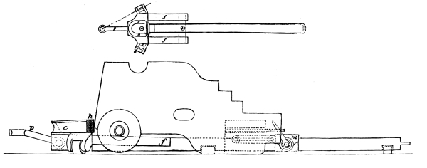
Directing-Bar Carriage.
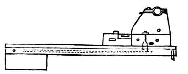
Boat-Carriage.
The carriage is provided with holding-down clips, and the recoil is checked by a breeching whose ends are made fast to the brackets, the bight passing around a bollard on the forward transom of the slide.
Mountain-Carriage.
The mountain-carriage is similar to the English field-carriage except the elevating-gear, which consists of a plain elevating-screw to which a hand-wheel and pinion gear.
Mitrailleuse Saddle.
This consists of a pillar whose lower end ships in a socket in the ship’s rail, and whose upper end branches into a fork to support the trunnions. A longitudinal support projects from the pillar, which holds a pivoted arm by means of a clamp. This gives a quick motion for elevating or depressing. The end of the pivoted arm holds an ordinary elevating-screw for slow motion.
Hotchkiss Saddle.
See United States Gun-Carriages.
GUNPOWDER.
The gunpowder used in the French service is classified according to the size of grain.
Wetteren powder, named from the place of manufacture in Belgium, is a large-grained cubical powder used in guns of the model 1870.
Ripault powder, named from its place of manufacture in France, is an ordinary-sized cannon powder used in all guns, except the above.
Hunting powder is a small-grained, highly-glazed powder used in revolver cartridges.
B powder, of a slightly larger grain than the hunting, is used in Chassepot rifle cartridges.
Musket powder is used in the manufacture of primers, fuses, and signals.
CARTRIDGES.
Cartridge-bags are made either of parchment or serge. For the smaller calibres they are of parchment.
Each cartridge is marked in black with the calibre of the gun for which it is intended, the weight of charge, monogram of the place where it was filled, and date of filling.
Cartridges are kept aboard ship in brass or copper tanks of various forms having water-tight covers.
PROJECTILES.
The projectiles used in the French Navy are shot, shell and case-shot. There are two kinds of shot, cylindrical and ogivo-cylindrical, corresponding to the shape of the head; the cylindrical being used only in the calibres above 19 cm. They are all steel. The ogivo-cylindrical shot are used in all calibres above 14 cm., and are either of steel or chilled cast-iron. Shell are of cast-iron, and are similar in shape to the ogival shot.
Projectiles, Model 1864.
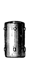
Armor-Shot.
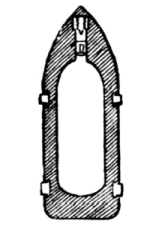
Shell.
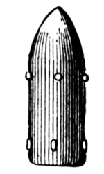
Solid Shot.
Projectiles, Model 1870.
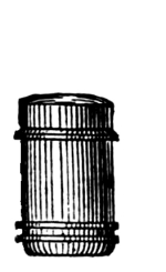
Armor-Shot.
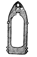
Shell.
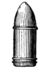
Solid Shot.
These projectiles are differently mounted for the different models. For the model 1870 the mounting consists of a forward ring of zinc or cast-iron just back of the shoulder of the shell, slightly smaller than the diameter of the bore across the lands. Its object is simply to keep the forward end of the projectile centred. A rear ring of copper, of a diameter slightly greater than that of the bore across the grooves. This ring brings up in its seat in the shot-chamber, and on firing the bands are scored and rotate the projectile. Around the surface of this ring are two or three grooves, cut to receive the metal displaced by the lands on firing. These projectiles carry at their base a light wire grommet to facilitate handling them.
For the model 1864-67 the projectiles are provided with studs, there being two rows. The forward studs take in the grooves and give the twist to the projectile; the rear ones hold the base of the projectile centred, and according to the calibre of the piece they travel in the grooves or on the lands. For the heavy projectiles, where the rear studs travel on the lands, there are provided three small intermediate studs which bring up in false grooves provided for the purpose, keeping the projectile from going too far forward in the bore when loading. These studs are sheared off on firing. The studs are made either of zinc or bronze. Projectiles for the bronze muzzle-loaders are similar to the model 1864.
Case-shot are of the ordinary type, and have neither studs nor belts.
Sea-weed wads are used with all projectiles except those of the model 1870. These are used in order that the powder-charge may act with a more gradual effect on the projectile at the start. Placed between the charge and the projectile, their rapid compression gives room for the powder to expand and burn more slowly at the first instant.
FUSES.
Percussion fuses are used in all shell except the 25-pdr. and 8-pdr. boat-guns, which use time-fuses.
The percussion fuse consists of a hollow cylindrical bronze body having a solid conical head. At the bottom of the cylinder is screwed a copper firing-pin. The centre of the cylinder is occupied by a brass plunger carrying a charge of hunting powder. The forward end of this plunger carries a wooden plug which is hollow and filled with detonating composition. The plunger is held in position by two iron pins upon which the base rests, and two leaden stops through the wall of the fuse entering the shell of the plunger. These stops are not broken by the start of the projectile, but by its shock on striking an object. The bottom of the fuse, being covered by shellac-paper, is blown away by the charge of powder in the plunger, and the flame is communicated to the charge.