PART II. NAVAL ORDNANCE. (continued 2)
Reading edition
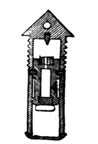
Percussion Fuse.
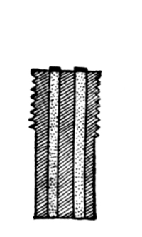
Time-Fuse.
The time-fuse for boat-guns consists of a brass body having two longitudinal chambers for fuse-composition columns of different times of burning. For the 23-pdr. the times correspond to 1500 and 3000 metres; for the 8-pdr. they correspond to 1100 and 2200 metres. The longer column is always uncapped on loading. The different times are distinguishable by the difference in the caps. That for the long time is of wire; for the short time it is of leather covered with a red wafer.
PRIMERS.
The primers are of two kinds, percussion and friction. The former seal the vent entirely on firing, and are only used in guns having vents through the breech-block (Model 1870). Friction primers are used in all guns having vertical vents.
The percussion primer consists of a body of brass or copper, slightly conical and having a solid head. Into this body screws a small steel anvil carrying an ordinary percussion-cap, which, when the anvil is screwed home, bears against the primer-head. The remainder of the body is filled with fine hunting powder, and the bottom is closed by a shellacked wafer.
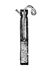
Quill Primer.
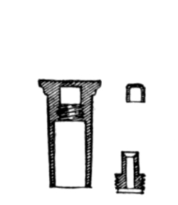
Percussion Primer.
The friction primer consists of two quill tubes, the lower and larger one being filled with fine musket powder, the bottom being sealed with wax. The upper is filled with fulminating composition, and has passing through its centre a brass friction-wire corrugated along its length. The exterior of the wire is formed in a loop for hooking on the firing laniard. The upper part of the primer is closed by a block of wood forming a fairleader for the friction-wire. A small independent loop is attached to the head of the primer, by which it may be withdrawn from the vent without touching the friction-wire.
SIGHTS.
The sights used in the French Navy are all side-sights, and for the most part the tangent-sights are inclined at a permanent angle.
The front-sights are conical in shape, and are screwed into the rim-bases.
The tangent-sights are square in section, working in boxes screwed to the face of the breech. They are graduated to full and half cable-lengths (200 and 100 metres). As a rule, guns are sighted on the left side, although provision is made for a right tangent and front sight. Sights are graduated on the left side for shell and on the right for shot, the graduations being all carried across the rear face. In general there is a short and a long sight, the long one being used for distances greater than 30 cables (6000 metres).
ACCESSORIES.
The loading-plate is a plate which attaches to the breech of the gun when the breech-block is open; along the bottom of this plate is a groove which forms a prolongation of the bottom groove of the gun (not applicable to model 1870); the projectile being hoisted to the level of the bore is landed on this plate, and is then in position to be rammed home. For small projectiles this plate serves as a shell-bearer for transporting projectiles, being provided with side handles.
The shell is brought to the loading-plate on covered decks by means of a tackle appended to a roller working on a traveller. The projectile being hoisted from the deck is pushed along on the traveller to the plate. In turrets the projectile is hoisted and swung by means of a davit.
The passing-box for the cartridge is made of leather with an ordinary close leather cover.
The rammer and sponge are of the old-fashioned type.
In calibres of a nature above 16-cm. a leather guard is always used in loading, to cover the gas-check and prevent injury from shocks in loading.
A system of guards against firing the gun before the breech-block is entirely closed is attached to the breech or the breech-block. In guns of the model 1864 the guard consists of a small hollow cylinder with funnel-shaped ends, acting as a sort of fairleader for the firing laniard. On the laniard itself are worked three turk’s-heads which, when the laniard is rove through the fairleader and hooked to the primer, come forward of the forward edge. A small spring is attached to the closing-stop of the handle, which projects into the funnel and will not permit the laniard to pass. When the breech is closed, the crank pressing against the closing-stop pushes back the spring and allows a free passage to the laniard. In guns of the model 1870 the guard consists of a small disc which slides over the vent when the breech-block is opened, and remains there so that a primer cannot be inserted until the block is closed and locked.
German Ordnance.
A = Over all.
B = Rifled Bore.
C = Powder Chamber.
Name, Nature, and Classification. Calibre. Length.
A B C
In. In. In. In.
Krupp’s pattern steel Breech-loaders.
30½ cm. hooped 12 264 172 54.7
28 cm., hooped and tubed 11.15 240 171 46.1
28 ” hooped 10.34 240 171 46.1
26 ” long hooped 10.24 225 138.5 55.3
26 ” short ” 10.24 205 128 42.1
24 ” long ” 9.27 206 136 38.4
24 ” short ” 9.27 185 115.4 38.4
21 ” long ” 8.24 185 124.6 33.7
21 ” short ” 8.24 154 96.8 31.4
17 ” long ” 6.8 167 107.5 40.8
17 ” short ” 6.8 134 92.0 24.7
17 ” short, light hooped 6.8 136 92.7 25.7
15 ” long hooped 5.87 152 105.8 27
15 ” short ” 5.87 129 86.8 28.5
15 ” tubed 5.87 128 86.8 23.5
12 ” hooped 4.74 115 85.7 14.7
8 ” heavy 3.19 76 57.6 8.4
8 ” light 3.19 76 57.6 8.4
8 ” 2.20 62 45.9 7.7
4 ” 1.54 69 54.7 9
D = Number of Grooves.
E = Twist of Rifling.
F = Gun, including Breech-block.
G = Breech-block.
Name, Nature, and Classification. D E Weight.
F G
Calib. Lbs. Lbs.
Krupp’s pattern steel Breech-loaders.
30½ cm. hooped 72 45 78,980 2,970
28 cm., hooped and tubed 36 70 60,500 2,244
28 ” hooped 36 70 60,500 2,244
26 ” long hooped 36 50 48,400 1,980
26 ” short ” 36 50 39,600 1,980
24 ” long ” 32 70 34,100 1,375
24 ” short ” 32 65 31,900 1,375
21 ” long ” 30 68 21,450 858
21 ” short ” 30 59 19,800 858
17 ” long ” 30 45 12,320 495
17 ” short ” 30 59 11,000 484
17 ” short, light hooped 30 45 7,590 411
15 ” long hooped 24 45 8,800 319
15 ” short ” 24 68 7,700 319
15 ” tubed 24 65 7,040 391
12 ” hooped 18 60 3,014 178
8 ” heavy 12 46 714 64
8 ” light 12 46 650 64
8 ” 12 46 500 55
4 ” 12 70 156 9
A = Preponderance.
B = Carriage.
C = Slide.
D = Height of Axis of Bore above Deck.
E = Chilled.
F = Common.
Name, Nature, and Classification. A Carriages. Projectiles.
B C D Full Weight. Bursting Charge.
E F E F
Lbs. Lbs. Lbs. In. Lbs. Lbs. Lbs. Lbs.
Krupp’s pattern steel Breech-loaders.
30½ cm. hooped 51,040 102 715 609.5 8 22
28 cm., hooped and tubed 24,200 102 561 477 7.7 25.3
28 ” hooped 24,200 102 561 477 7.7 25.3
26 ” long hooped 16,500 18,075 67 411 367 5.28 17.27
26 ” short ” 8,849 13,831 48 411 367 5.28 17.27
24 ” long ” 8,349 13,831 48 308 261 3.19 15.4
24 ” short ” 5,082 8,756 39 308 261 3.19 15.4
21 ” long ” 4,290 6,556 40 216 175 2.75 10.45
21 ” short ” 4,114 6,402 42 216 175 2.75 10.45
17 ” long ” 2,772 4,576 41 123 112 1.21 9.24
17 ” short ” 2,321 3,400 33 121 99 1.21 6.6
17 ” short, light hooped 2,156 2,068 34 117 112 1.32 5.94
15 ” long hooped 16.5 2,057 3,806 38 78 78 7.7 6.5
15 ” short ” 48.4 1,947 2,530 34 78 61 7.7 4.4
15 ” tubed 62.7 1,908 2,640 35 78 61 7.7 4.4
12 ” hooped 22.2 1,595 2,750 47 38 33 2.48
8 ” heavy 15.4 1,100 33 9.5 .6
8 ” light 14.7 880 35 9.5 .6
8 ” 14 246 246 35 6.7 .6
4 ” Turntable. 125 .28
A = For Steel and Chilled Shot.
B = For Common Shell.
C = Saluting.
D = Penetrating Power.
Name, Nature, and Classification. Powder Charge. D
A B C
Lbs. Lbs. Lbs. In.
Krupp’s pattern steel Breech-loaders.
30½ cm. hooped 158.4 158.4 16.4
28 cm., hooped and tubed 132 132 14.4
28 ” hooped 132 132 13.3
26 ” long hooped 107.8 107.8 17.6 13
26 ” short ” 107.8 107.8 17.6 11.5
24 ” long ” 59.4 44 17.6 11.27
24 ” short ” 59.4 44 17.6 10.05
21 ” long ” 41.8 30.8 13.2 8.9
21 ” short ” 35.2 26.4 13.2 8.55
17 ” long ” 26.4 22 6.6 7.25
17 ” short ” 17.6 14.3 6.6 7.33
17 ” short, light hooped 16.5 16.5 6.6 7.88
15 ” long hooped 18.7 15.4 4.4 6.7
15 ” short ” 13.2 12.1 4.4 6.58
15 ” tubed 13.2 12.1 4.4 5.6
12 ” hooped 7.7 4.62 2.31 5.6
8 ” heavy 1.1 1.1
8 ” light 1.1 1.1
8 ” .98 1.1
4 ” .41
E = Chilled.
F = Common.
Name, Nature, and Classification. Initial Velocity. Working Effect.
E F E F
Ft. Ft. Foot Tons. Foot Tons.
Krupp’s pattern steel Breech-loaders.
30½ cm. hooped 1,591 1,623 12,584 11,176
28 cm., hooped and tubed 1,515 1,640 8,960 8,931
28 ” hooped 1,515 1,640 7,210 8,931
26 ” long hooped 1,587 1,640 6,802 6,876
26 ” short ” 1,430 1,387 4,835 6,466
24 ” long ” 1,502 1,391 4,625 3,511
24 ” short ” 1,469 1,355 4,625 3,327
21 ” long ” 1,476 1,394 3,275 2,348
21 ” short ” 1,312 1,394 2,587 1,970
17 ” long ” 1,548 1,525 1,944 1,809
17 ” short ” 1,279 1,279 1,399 1,127
17 ” short, light hooped 1,325 1,341 1,437 1,411
15 ” long hooped 1,623 1,615 1,431 1,172
15 ” short ” 1,477 1,591 1,030 1,072
15 ” tubed 1,358 1,446 1,001 888
12 ” hooped 1,476 1,230 584 345
8 ” heavy 1,118 84
8 ” light 1,118 84
8 ” 1,135 66.5
4 ” 1,837
GUNS.
Smooth-bore guns are now entirely obsolete. The rifled ordnance is constructed entirely on the Krupp system of steel breech-loaders. Although the Krupp system taken as a whole is represented by three distinct types of guns corresponding to different developments of the breech-closing mechanism, but one, the latest development, appears in the armament of war vessels. There are also two types corresponding to the building of the body of the guns, but these are quite similar, the difference being simply in the use of a number of thin hoops in the later guns to replace a few thick hoops in the earlier construction. All guns except the 9-pdr. bronze breech-loader are built entirely of steel. The broadside-guns of medium calibre are divided into two classes, the long and the short gun, the latter being intended for vessels whose beam or displacement will not permit the use of the longer and heavier gun. The short gun of one calibre is, however, in all cases a more powerful gun than the long one of the next lower calibre.
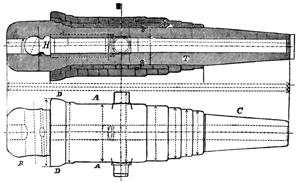
All naval guns except the converted 15-cm. calibre have a steel body strengthened by hoops. The converted gun has no hoops, it having been strengthened by boring the body up to form a casing, which was shrank over a steel tube. This tube extends from the breech-block to about one calibre beyond the muzzle.
The 30½-cm. gun has three tiers of hoops, the 26-cm. and 24-cm. guns have two tiers, and the remainder one tier. The trunnions in all cases are in one with one of the hoops. The hoops are prolonged forward of the trunnions, diminishing rapidly in thickness.
The bore is rifled on the multigroove plan, the rifling differing slightly according to the projectile which the gun was intended to fire. Formerly all projectiles were provided with a zinc rifling-jacket, and for such, a smooth shot-chamber was necessary, the rifling stopping at its forward end. The French style of copper bands being now used, the rifling is continued through the shot-chamber to the opening of the powder-chamber. With the zinc jackets, the grooves decreased in width from the breech towards the muzzle in order to keep a firm grip on the easily yielding metal throughout the bore. With the copper rotating belt the grooves are of the same width throughout.
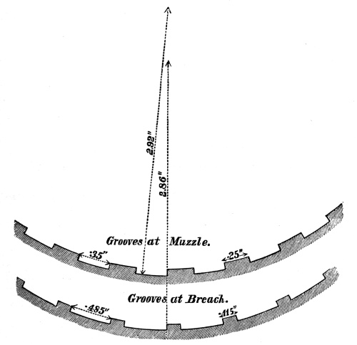
The powder-chamber is cylindrical, and about the depth of a groove wider than the diameter of the bore across the grooves. It is connected with the shot-chamber by a short cone which brings up the rear rifling-belt of the projectile in loading. In general the powder-chamber is concentric, but there are two calibres (26 cm. and 15 cm.) in which it is eccentric, its axis being slightly above that of the bore. The powder-chamber ends in a gas-check seat, which is coned and slightly countersunk forward to receive the Broadwell gas-check.
Just behind the gas-check seat is the transverse breech-block seat, three of its sides being flat, and the rear or bearing side being hollowed out to a semicircular wall.
The bore of the gun is continued straight through the breech, forming a loading-hole in rear of the breech-block.
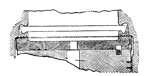
Broadwell Gas-Check, Seat, and Face-Plate.
The breech-blocks of all guns traverse the breech transversely, and they are all single blocks. There are two patterns, differing only in the shape of the rear portion, one being cylindrical and the other flat. The latter type is found only in guns where formerly a double wedge (the Kreiner system) was used, so that in changing to the single wedge there was not metal enough left in rear to permit hollowing out that face.
The breech mechanism consists of the breech-block, the covering-plate, the transporting-screw, the locking-screw, the curb-chain, the gas-check, the face-plate, and the vent.
The breech-block is a heavy solid steel block, generally cylindro-prismatic, sometimes square in section. The rear of this block is not parallel to the front, but inclined in wedge shape at an angle of 1° 55´. The prismatic part of the block is slightly wider than the diameter of the cylindrical part, forming at the junction an edge at the top and bottom, which serves as a guide for the block in sliding in and out. The block is much shorter than the width of its seat, so that it is not necessary to entirely withdraw it in order to unmask the bore. Except for special guns, the breech-block always draws out to the left, and its left end has bolted to it a steel plate of the same size, called the covering-plate.
This plate merely serves as a holder for the locking and moving mechanism. With light breech-blocks a shackle-handle bolts to the centre of this plate for withdrawing the block. With the heavier calibre, where the block cannot be moved by hand it is worked in and out by a screw.
This transporting-screw lies along the top of the block from end to end, revolving in journals; one half of the circumference only lies in the block, the other half, projecting, takes in a half-female thread in the upper wall of the gun. The end of the screw projecting beyond the covering-plate is squared so as to permit a crank to be shipped. In this manner, by revolving the screw, the block is worked out or in.
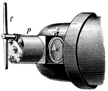
Breech-Block (front).
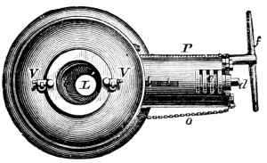
Breech-Block (rear).
The locking-screw, as its name implies, serves to lock the block. It is on the rear part of the block, placed like the transporting-screw only half in the block, so that its thread will take in the gun-wall. Besides locking the breech, it forces the block close home and releases it, taking the strain from the transporting-screw, which might otherwise be bent by the shock of firing. The threads of the locking-screw, except the first or outer turn, are cut away for one third of the circumference, so that the action of locking and unlocking is similar to that of the French mechanism. The outer thread is left full to cover the joint when the breech is closed. A stop on this thread limits the revolution of this screw by catching on the covering-plate, so that when brought up at one point it shows the breech to be locked, and at the other that it is unlocked. The same crank is used to work the transporting-screw and the locking-screw.
The curb-chain is a short chain which limits the withdrawal of the block and prevents it from being pulled all the way out. One end is fast to the lower end of the covering-plate, and the other to the gun just underneath.
The Broadwell gas-check is a steel ring, fixed in the gun semi-permanently; that is, it does not move with the breech-block, although it may easily be knocked out. This ring is coned around its outer edge, which is turned up cup-shaped. The inner side of this cup-rim is shaped in gutter form, in order to make the best distribution of the gas pressure. The whole middle is cut away, of the same size as the powder-chamber, so that the charge can be passed through it. Three concentric scores are cut around the back of the check, the idea being to break the force of any gas that may escape by making it suddenly expand and contract as it forces its way by them. The rear of the gas-check projects slightly beyond the rear of its seat.
The face-plate is a steel disc attached to the forward face of the block, and forming the bearing surface for the gas-check. This plate has a slightly greater diameter than the height of the block. It fits into a seat cut for it, and is prevented from turning or falling out by a little dowel and a spring-catch on the upper part of the block. As this plate wears, thin washers of brass or copper are fitted behind it. The rear face of this plate is fitted with grooves, which, from the shock of firing, attach and hold fast these washers. Each gun is provided with a spare face-plate and gas-check, and aboard ship a reserve gas-check is supplied in addition for each pair of guns.
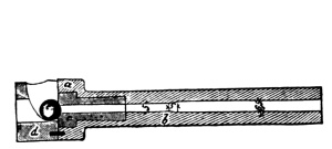
Vent-Bush and Vent Gas-Check.
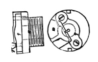
Vent-Piece, showing Hook for Head of Primer.
The vent is pierced in a steel vent-bush, which traverses the breech-block in the axis of the bore. The forward part of the vent is provided with a simple arrangement for preventing the escape of gas. A small vertical chamber contains a steel ball, which in its normal position covers the vent completely. When the primer is fired, the flame drives the ball up and passes on to the cartridge, but the back-flame also striking the ball drives it down over the mouth of the vent again and seals it. The rear end of the vent-bush is provided with a hook for holding the primer in place for firing. The hook itself completely covers the mouth of the vent, having a slit for the friction-bar of the primer. It is so shaped on the rear side that the back-flame through the vent throws it back. A small knob is fixed to it for convenience in hooking and unhooking. This hook is so screwed on the end of the vent-bush that it may be easily removed, and after removing the vent-bush itself may be easily backed out of the block. Aboard ship each gun is provided with two reserve vent-bushes.
The vent of the 8-cm. boat-gun is a right-angled one, pierced from the face of the block to its centre, and then, turning at right angles, passes up through the block and the wall of the gun. The joint at the top of the block is made tight by copper bearing surfaces. This vent has neither the ball for checking back-fire nor the primer-hook.
All guns except boat-guns are provided with a loading-box. This is a hollow steel cylinder fitting in the loading-hole. When in place, its forward end rests against the back of the gas-check, while the rear end comes to the end of the cascabel, being provided with steadying hooks that hook into the cascabel. The charge being entered in this loading-box is pushed directly home. The boat-guns have no loading-box, but instead the right end of the breech-block is prolonged and a loading-hole is cut through it.
The transporting-screw removes the block by about one and three quarter turns, as it has a very sharp pitch. Below the calibre of seventeen centimetres there is no transporting-screw, the locking-screw serving both purposes.
CARRIAGES
Broadside-Carriage for the Heavy and Light 8-cm. Guns.
This carriage is of the simplest construction. It consists of two plate-iron brackets connected and braced by through-bolts. It is mounted on two trucks forward, and a single broad wooden rear chock. For the light gun, breeching-holes are made in the forward part of the carriage, the ends of the breeching shackling to bolts in the ship’s side; for the heavy gun, the ends of the breeching shackle to the brackets, the bight being shackled under the centre of the port. These carriages are provided with breast-pieces for training, a training handspike, and tackles for running out and in. The light gun is provided with the ordinary elevating-screw, but the heavy one has a rack, pinion, and hand-wheel for rapid and extreme elevating. The pinion is held by a compressing lever. The trucks are of cast-iron with brass journals.
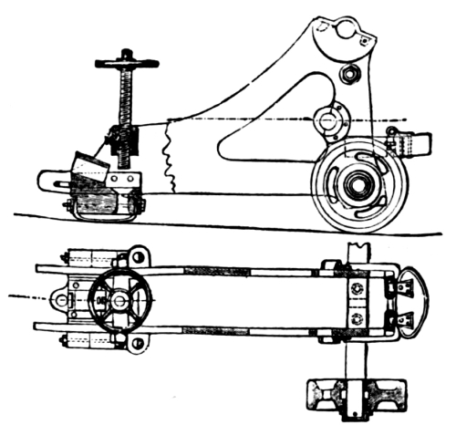
Broadside-Carriage for 8-cm. Boat-Gun.
Broadside-Carriage for 12-cm. and 15-cm. Guns.
This carriage consists of two plate-iron brackets, a forward transom, and two bottom plates. The trunnion-holes, as in all other carriages, are broadened by brass journal-plates. It rests on two cast-iron trucks forward, and in rear on a rear chock. A swivel roller is fixed in the middle of this chock with a forked attachment, by which a trail handspike may be shipped at an angle of about 45°. Heaving down on this handspike lifts the rear of the carriage on the roller, and the lateral movement permitted to the handspike enables the carriage to be steered out. Bolted to the forward transom is a fork which, projecting forwards, forms a pivoting point. In running out it is necessary to run the end of this fork (which has jaws for the purpose) against the bolt provided for it to pivot about. The rear chock is of plate-iron with a brass shoe.
The recoil is governed by what is called the Brookwell apparatus. This consists of a drum with a friction-band controlled by a lever at the left side. Turns of a breeching are wrapped around the drum, the ends being fast to it, and the bight shackling to the pivot-bolt in the centre of the port. In running out, cranks ship on the ends of the axle, and the breeching is in this manner wound on the drum by heaving down the brake, the friction-band is tightened on the periphery of the drum, thus easing the recoil. The power of the cranks is not sufficient to enable the gun to be run out by this arrangement, and side tackles have to be used. A reserve breeching is also kept rove, through breeching-holes in the forward part of the brackets.
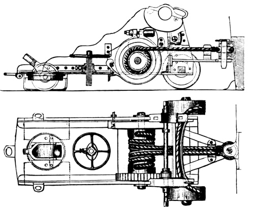
Brookwell Broadside-Carriage.
The ordinary elevating-screw is used, working in a screw-box through the rear transom.
Slide-Carriages.
Slide-carriages are used with all guns of seventeen centimetres and upwards. These carriages are classified as either carriages with fixed or with movable slides; and each of these is subdivided into slides for firing from ports or over the rail. As the necessities have arisen for modifications, changes have been made in the details of these carriages and slides, although the general form has remained the same. As a rule, the pivot centre of the slides is either in the middle of the gun-port or close to the spirketing, always forward of the body of the slide.
Slide and Carriage for Short 24-cm. and 21-cm. Guns, Pattern 1868.
The carriage-brackets are of the double-plate pattern, having a wrought-iron frame, and, connected by a bottom plate, forward and rear transoms secured by angle-irons. The carriage rests on rollers, both front and rear being on eccentric axles. The rear rollers are thrown into action by means of levers, and the act of lifting the rear of the carriage on the axle throws the front rollers into action. The bottoms of the brackets are shod with brass friction-plates for travelling on the slide. The elevating-gear consists of a metal rack and pinion. The front edge of the rack is kept against the pinion by a smooth roller against the rear edge. The pinion is worked by means of a lever and capstan-head outside of the bracket. A screw-brake holds the gear fast, it being worked by a lever. When this lever is thrown up the brake is off, when down it is set fast. The carriage is run out and in by means of tackles, but one tackle being used on each side. The carriage-block for this tackle is a double block working on a hinge midway on the forward end of the bracket. The compressing arrangement is the Elswick pattern (see English Ordnance) of iron bars and plates worked by rocking levers, and having a compressing lever outside of one bracket and a regulating lever outside of the other, the former being provided with a trip for automatic compression. The carriage has also front and rear holding-down clips bolted to the bottom plate.
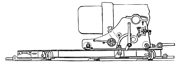
Carriage and Slide for 21-cm. Gun.
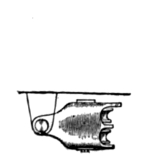
Slide Tackle-Block.
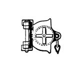
Hinged Carriage Tackle-Block.
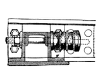
Buffer.
The slide consists of two heavy double T-iron rails bent in front. They are connected by three bottom plates, and an angle-iron joining the front ends. Seven compressor-bars are laid in the centre of the slide, and from the middle to the rear bottom plate a wooden platform is laid. Two railway buffers are provided at either end for taking up the shock in violent running in or out. The fighting pivot-flap is a stout bar hinged to the front end of the slide so as to have vertical motion; a single eye in the end enters the jaws of the pivot-shackle in the centre of the port. The slide rests on front and rear rollers, the front ones being permanently in action and the rear ones, on eccentric axles, being thrown into action by levers. The 24-cm.-gun slide is provided with a windlass for running in and out and training. This consists on each side of the slide of a pinion turned by crank and gearing in a spur-wheel which carries the bollard. The out and in tackles are carried directly to the windlass. For training, the fall of the tackle is rove through a leading-block hooked just forward of the windlass to give a fair lead. Housing pivot-flaps are hinged at each end of the slide, which drop and key over bolts projecting from the deck. Bow and stern pivot-slides are provided with transporting rollers, which ship just inside the traversing rollers and work on eccentric axles. There are three traversing circles on the deck: the front and rear are for the front and rear rollers, the centre one holds the slide when it buckles from the position of the gun on it.
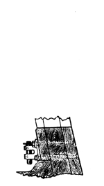
Centre Pivot-Bolt.
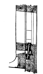
Centre-port Pivot-Bolt.
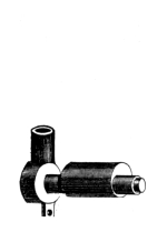
Eccentric Axle and Handspike Socket.
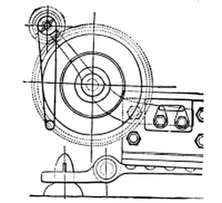
Windlass for Training and In Tackles.
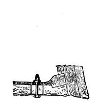
Front Housing-Bolt.
Carriage and Slide for the Long 21-cm. Gun, Pattern 1869.
This pattern only differs from the former in being heavier braced. The fighting pivot-flap is not hinged, but is three-armed and secures to the slide by shackle-bolts. Shifting slides are provided with a third pair of rollers just forward of the centre of the slide, which are thrown in action when pivoting around the rear pivot-bolt; from their position, they lift the forward rollers clear of the deck when in action.
Cabin-Carriage for the Long 21-cm. Gun.
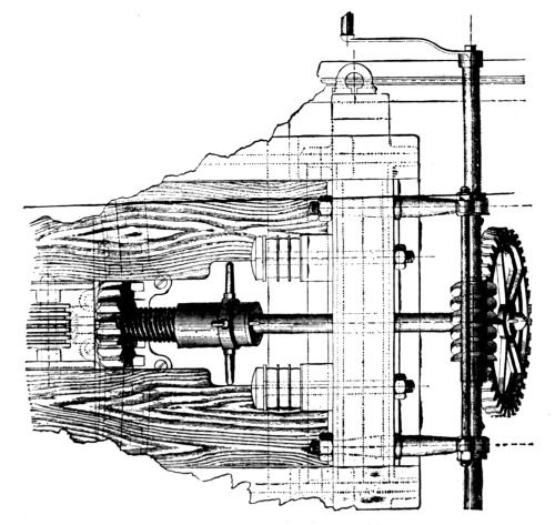
Training-Gear for Cabin-Carriage.
Owing to the cramped space for training bow and stern-guns, and the necessity for rapid training, geared train-wheels are used in this slide in place of the regular training-tackle. A sunken rack in the deck, midway of the slide, forms the track for a heave mitre-wheel, the axle of which cants up to the rear and is held by a journal in the rear transom. On its outer end a large spur-wheel gears in an endless screw which is revolved by cranks. The axle of this endless screw also carries the windlass-drum for aiding the in and out tackle; it is therefore necessary that the screw and spur-wheel can ungear. For this purpose the main axle is in two parts, the rear one carrying a heavy sleeve which is free to revolve, and has a female screw-thread worked in it and handles outside for turning. A male screw-thread is worked on the forward axle, and the end is also slotted to allow a tenon on the after axle to fit it. By revolving the sleeve, then, the rear axle is pushed to the rear through the rear journal, thus releasing the spur-wheel from the screw. In this carriage there is also a slight modification of the arrangement for jamming the elevating-gear. There is also but one compressor-lever working as a ratchet-lever in a ratchet-wheel on the compressor-axle. The slide-rollers of this type are on concentric axles in action permanently.
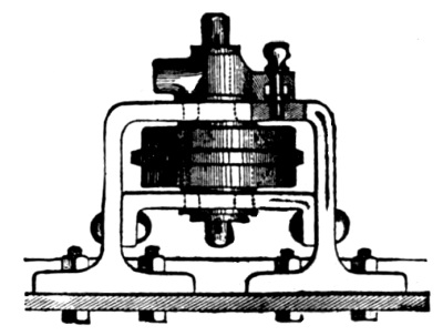
Slide Rear Roller, showing Manner of Pinning the Roller in Action.
Slide-Carriage for the Long 21-cm. Gun, Pattern 1873.
(Plan.)
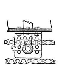
(Section.)
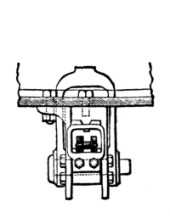
Stirrup on Carriage for Endless Chain.
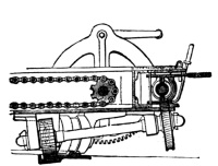
Rear of Slide, showing Training-Gear, Chain-Roller, Crank, and Recessed Rear Roller for taking Recoil.
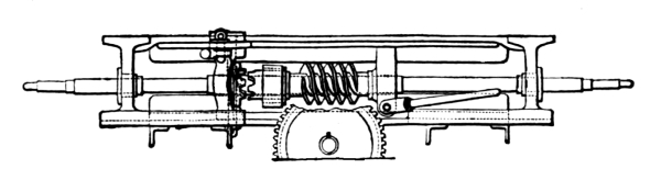
Axle-Grip for Putting Training-Gear in and out of Action.
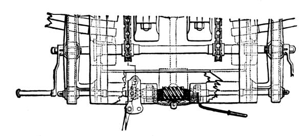
Training-Axle and Rear Chain-Axle with Gearing.
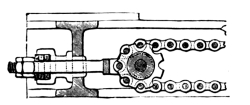
Front Chain-Roller.
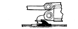
Recoil-Hook and Countersunk Traverse.
This pattern differs from the 1868 one in having a higher slide and lower carriage, gearing for training the gun, and the Scott endless chain for running out and in. The forward rollers work automatically as in the former pattern. The levers for the rear rollers ship inside the brackets, and heave down instead of up for putting in action. The chain-clamp consists of a stirrup moving vertically, which carries the chain freely when down, but when hove up by a lever jams the links in a toothed rack. A stop on the outside of the brackets holds the stirrup when lifted by the lever. An endless chain travels on each side, but only one is used, the other one being kept as a reserve. The slide-rollers are constantly in action, and are arranged to divide with the pivot-bolt the strain of the recoil. To accomplish this the circle, or racer, is made quite narrow, and the middle part of the roller is hollowed out so as to grip both sides of it. The training-gear is similar to the one for the cabin-carriage, except with regard to connecting the screw and spur-wheel. The screw is worked on a loose sleeve, which at its left end is toothed. A movable toothed gripe revolving with the axle, but free to move along it, is brought to the sleeve or retracted from it, as desired, thus revolving the screw or leaving it free on the axle. The gripe is moved by a lever. The screw-shaft is revolved by means of pinions at each end, which gear in large spur-wheels. The axle of these spur-wheels carries, also, inside the slide, the rear rollers of the endless chain. Outside of the spur-wheels are the cranks. By this arrangement, the same gearing runs the carriage in or out and trains the slide. If the gripe be backed clear of the screw-sleeve, the training-gear is thrown out of action, and by heaving up the stirrup the carriage is clamped to the chain and run in or out. Reversing these processes, the carriage is thrown out of action and the slide is trained to the right or left.
Slide-Carriage for the Short 26-cm. Gun, Pattern 1875.
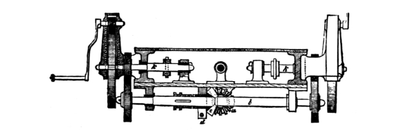
Gearing for Short 24-cm. Slide.
This pattern is similar in general to the one just described. The forward carriage-rollers are automatic eccentric ones, the rear work by levers, the Scott chain-gear is used for running in and out, and similar training-gear is used. The pivot-bolt does not bear any of the shock of the recoil, it being taken up partially by the slide-rollers and partially by a cramp fixed to the forward end of the slide and travelling in an undercut circle on the deck. The slide inclines to the rear to facilitate running out.
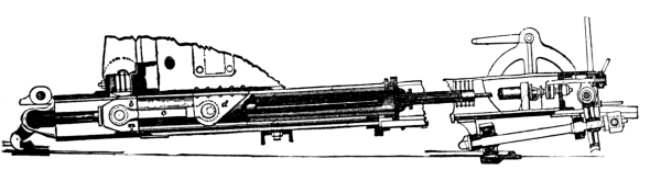
Hydraulic Recoil Cylinder and Piston.
The main difference between this carriage and the others is the use of a hydraulic recoil cylinder working in a manner quite different from the English style. The cylinder itself is of steel, and is hung on trunnions to the carriage. The piston-rod runs completely through it, and is secured at each end of the slide. Both ends of the cylinder are closed by cast-iron heads with stuffing-glands. The forward head, being the one which receives the violence of the recoil, is secured by a heavy iron brace which fastens to the cylinder trunnions. The cylinder is filled with glycerine, the filling and drip holes being both at the rear end. It rests and slides on a bed fixed along the middle of the slide. The arrangement for checking recoil, and also for governing violent movements of the carriage, is contained in the piston-head. This head is made up of two discs which are bolted together, the interior face of each being hollowed out so as to form a chamber in the piston-head. Four holes are bored through each disc into the chamber, but they are not in line, the hole in one disc coming opposite a blank in the other. Four small valves close the inner ends of the forward holes, and these valves are secured to a plate which is free to move back and forth in the little chamber, and thus open or close the holes. A rod from the back of this plate passes through the hollow rear end of the piston-rod, and seats against a carriage-spring on the rear transom of the slide. This spring holds the valves forward, closing the forward piston-holes. A small hand-lever on the valve-rod enables it to be drawn back, thus opening the valves at will. The action of the compressor is as follows: The recoil of the gun carries the cylinder to the rear and violently contracts the space forward of the piston-head; the oil is forced with violence through the forward holes, pressing back the small valves and escaping by the other holes to the rear of the cylinder. As the recoil ceases, the force of the spring carries the valve-stem and its valves forward again, closing the holes. The gun is held thus in position, as it cannot run out unless the valves permit the oil to pass into the forward end of the cylinder again. The pressure, however, comes against the back of the valves and keeps them closed. A slight turn of the hand-lever opens the valves, and the oil gaining free passage permits the gun to run out. The moment that the gun starts, however, to run out violently, a single movement closes the valves and the gun is held fast.
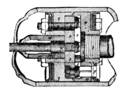
Piston-Head.
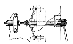
Rear End of Piston-Rod and Connections.
Slide-Carriage for the Short 24-cm. Gun, Pattern 1876.
This carriage differs in no important point from the last mentioned, except in the training-gear, which is more compactly arranged. The training-shaft carries on its rear end, instead of a large spur-wheel, a small mitre-wheel. Instead of the endless screw on the shaft, there is a mitre-pinion worked on a loose sleeve and having the same locking apparatus as the one before mentioned. The outer gearing for revolving the train-work is similar to what has been described; the axle carrying the endless-chain rollers, however, is not continued across the slide, but each wheel is independent, its axle seating in a journal inside the slide.
Slide-Carriage for 17-cm., 15-cm., and 12-cm. Guns.
These carriages are of the ordinary pattern and simple in detail. The carriage-rollers are like the others, automatic forward and worked by levers in rear. The elevating-gear is rack and pinion style for the 17-cm., and simple screw for the others. In the carriages previous to 1875, breechings are used. Where the gun is not a shifting one, the bight is rove through holes in the forward ends of the brackets; where it is shifting, the ends of the breeching shackle to the brackets. The forward slide-rollers are permanently in action, the rear ones are worked by levers. Where the slide is a shifting one, a third pair of eccentric rollers is midway of the slide and canted for rear-pivoting. The carriage is held on the slide by front and rear clips. Carriages later than 1875, unless they are of the newest type, have Elswick compressors; the latest have the before-mentioned hydraulic recoil cylinder in some instances, and in others the English style. These slides all have rear housing-bolts as above described. Where the fighting pivot-arm is long, a front housing-bolt and lip are used; if it is short, there is none. Tackles are used entirely for running in and out.
Half-Slide Carriage for the 17-cm. Gun, Pattern 1875.
(Side View.)
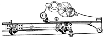
(End View.)
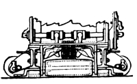
Half-Slide Carriage for 17-cm. Gun.
The general plan of slide and carriage is similar to the foregoing. The slide is, however, very low and short, its rollers being permanently in action. The carriage has two front rollers on eccentric axles worked by levers. The rear of the carriage is somewhat longer than ordinary, and under it is hung a single long roller, which, when the gun is run out, does not touch the deck. In recoiling it drops to the deck and supports the rear of the carriage. The recoil is checked by the Elswick compressor, and in addition a breeching is provided, whose bight runs through holes in the front of the bracket. Rack and pinion elevating-gear is used. In slides intended for shifting ports, the rollers can be turned around a vertical axis and be locked so as to move the slide sideways.
Slide-Carriages for Light Guns Firing over the Rail.
The only difference between these and the others is that the slide is much higher and is centre-pivoting. In order to take off the shock of recoil from the pivot-bolt, the slide-rollers overlap the circles on both sides.
Slide-Carriage for the 30½-cm. Gun for Armored Gun-boats.
The general principle of the carriage is the same as the ordinary one. Its front and rear rollers are the same, and the elevating-gear is the rack and pinion type, the power being increased in accordance with the greater weight to be moved. The carriage is heavier braced, having three transoms in place of two. There are no out-tackles or chain-gearing, the slope of the slide (6°) being sufficient to run the gun out by its own weight. When it is necessary to run it in, in-tackles are used, the falls being taken over windlass-heads on the rear hurter of the slide. The slide is centre-pivoting, and traverses on four heavy rollers which overlap the edges of the circles to take the force of the recoil. A cramp under the forward end of the slide moving in an undercut circle on deck also takes the recoil shock. The gun is traversed by gearing. Just inside the roller-circles is a circular rack into which a pinion gears; the inner end of the pinion-axle carries a mitre-wheel whose upper and lower cogs gear in mitre-pinions which are worked on loose sleeves on a vertical axle. Between these pinions, revolving with the axle, but free to move vertically, is an iron grip which catches in the upper or lower pinion, according as it is desired to sweep the gun to the right or left. The vertical axle passes down to the lower deck, where is a train-work with crank-handles to be revolved by six men. By means of the single grip arrangement between the mitre-pinions, the gun may be traversed to the right or left or stopped without reversing the motion of the crank-handles below. The hydraulic recoil cylinder above described is used to check the recoil and control the running out of the gun. A sheet-iron musket-proof shelter is raised on the slide for the protection of the gun’s crew. For lifting the projectile to the gun a derrick is fixed at the rear of the slide. The fall of the whip is taken around a windlass-head, and the davit is swung around by means of an endless screw and pinion.
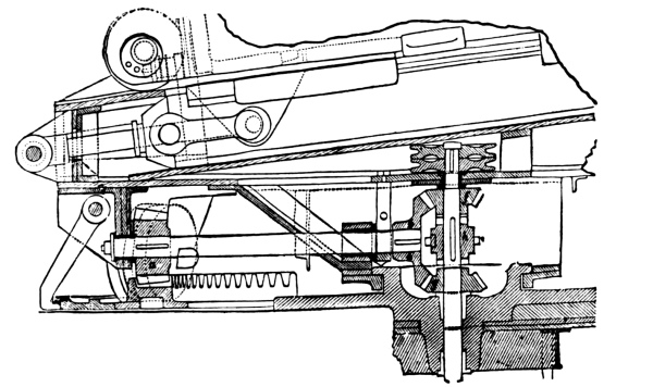
Front Half of Slide for Centre-Pivoting Gun-boat Carriage.
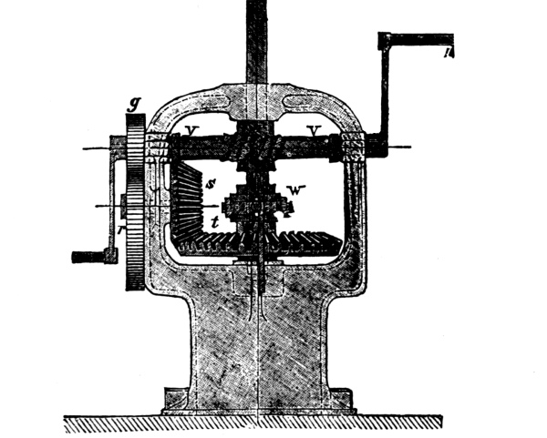
Gear below Deck for Revolving Gun-boat Carriage.
Turret-Carriage for the 21-cm. Gun (Arminius).
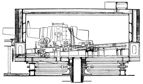
Turret-Carriage for Minimum Port. (See next page.)
The turret-slide is fixed, and forms a part of the turret. The rails incline forward at an angle of 6°, so that out-tackles are unnecessary. The carriage-rollers are of the ordinary type. But one lever is used in throwing the rear trucks in action, as there is not room to work on the inside of the carriage. For running in, two chains shackle to the turret in rear of the gun and pass over a drum in the centre of the carriage. The drum is revolved by gearing. The recoil is controlled by the Elswick compressor. The elevating-gear is the single-screw type.
Turret-Carriage for the 24-cm. Gun, Pattern 1874.
This carriage, intended for a small port, differs in height and shape from the previous ones in order to permit a vertical elevation and depression of the gun-trunnions. It is built on the double-plate plan, with heavy transoms and bottom plates. The four carriage-rollers are arranged in the usual manner, the levers for throwing the rear trucks in action being moved by a tackle. The elevating-gear is fixed to the chase of the gun forward of the trunnions. It is of the ordinary rack and pinion type, but does not connect with the carriage, being hung in a frame which projects from the trunnions. The gun is run in and out by means of the endless-chain gear, the gearing being connected to a long shaft outside of the turret, to which three hand-wheels are attached. These hand-wheels are of course underneath the upper deck, coming out directly under the port. The recoil is governed by a hydraulic recoil piston, the arrangement in this case being identical with the English system. (See English Ordnance.) The trunnions have three positions, the lower, middle, and upper. They are supported in a saddle whose arms travel in a framework in the brackets, being supported by iron blocks inserted through holes in the sides of the brackets. The saddle is raised by a hydraulic press, which is so fixed in the turret that the piston takes against the bottom of the saddle when the gun is run out. The details of this arrangement are precisely similar to those of the corresponding English turret-carriage. The slide-rails are fixed in the turret with a slope to the front of 5°. In addition to the chain nipping-gear and the hydraulic recoil piston, the gun-carriage is provided with bow-compressors on each side. (See English Ordnance.)
Boat-Carriages.
The boat-carriage complete consists of a wooden slide bound together in front and rear by iron plates, and a composite carriage made up of a wooden bed surmounted by an iron bed-plate and bracket-frames for the trunnions. Two buffers are put at the rear of the slide to take an over-recoil. The elevating-gear is the simple screw and hand-wheel. The compressor is a brass-faced block whose upper side takes in undercut spaces in the slide. The block is held up and tightened by a screw and hand-clamp. For transporting the boat-carriage and gun together a small block-cart is used, which is nothing more than a heavy, flat, wooden body provided with an axle and two gun-trucks.
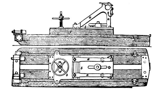
Boat-Carriage.
Field-Carriages.
The field-carriage is of the ordinary type, consisting of two straight iron brackets, strengthened along the upper edge by angle-irons, and curved to form a sole at the bottom. To this a trunnion socket-frame is bolted. The brackets are braced by transoms and by two side rods. An iron axle bolts to the under side of the brackets just in rear of the trunnion-holes. The wheels are wooden with brass hub-boxes and iron tires. The elevating-gear is of the plain screw and hand-wheel pattern. A limber is provided with this carriage which carries two ammunition-boxes, each of which holds six rounds of shell and the corresponding cartridges (not fixed to the projectile). The carriage itself also carries two ammunition-boxes of the same size.
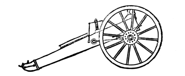
Field-Carriage.
GUNPOWDER.
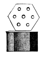
The gunpowder used for the majority of naval guns is of the kind known as prismatic powder. Of this there are two classes. The first, for use with the heaviest calibres, is solid; that for medium calibres is pierced with holes longitudinally—for the high calibres with one central hole, and for the medium with seven. Large-grained cannon-powder is used in shell-guns, whilst the usual classes of small-grained powder is used with small-arms and for shell-charges. Prismatic powder is invariably used for battering-charges in all calibres, the gradation with regard to time of burning being obtained by the holes pierced through the grains: slow powder, solid; medium, one hole; quick, seven holes.
PROJECTILES.
The projectiles used in the German Navy are shot, shell, case-shot, and shrapnel. Shot are either solid or hollow for the lighter calibres, and hollow for the heavy ones. They are of ordinary cast-iron, chilled cast-iron, and steel, the solid shot being invariably made of ordinary cast-iron. They are of two different types, according to the style of rifling arrangement. In the earlier patterns, all projectiles were provided with a lead belt extending from the shoulder to within about two inches of the base. To receive and hold this jacket, broad shallow grooves were cut around the circumference of the projectile, the ridges left having slots cut through them at intervals to resist the tendency of the jacket to slew around. The jacket was moulded around the projectile and zinc-soldered. Corresponding with the grooves in the projectile, there were grooves in the jacket to receive the overflow of metal forced back when the projectile took the rifling.
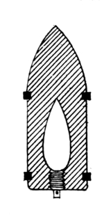
Chilled Shot.
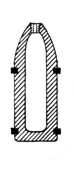
Common Shell.
27-cm. Gun.
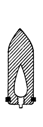
Chilled Shot.
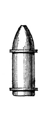
Common Shell.
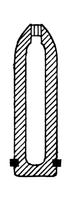
Long Shell.
15-cm. Gun.
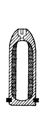
Segment Shell. 17-cm. Gun.
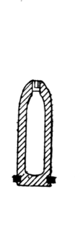
Common Shell. 8-cm. Gun.
In the late patterns, instead of a jacket, two rings are used; the forward one being for centring or holding steady the head of the projectile, and the rear and larger one for rifling. This rear one is provided with grooves to receive the overflow of metal. Both rings are copper. The steel and chilled shot are very similar in appearance.
Shell are similar in exterior shape and appointment to shot, and are all made of ordinary cast-iron. Double shell (see English Ordnance) are used with the 17-cm. and 15-cm. calibres.
Case-shot are of the ordinary pattern.
Shrapnel are only used with boat-guns, and are similar in construction to the English. (See English Ordnance.)
Solid shot are used only with the 17-cm. and 15-cm. guns.
Case-shot are not used with boat-guns.
Hollow-shot, shell, and case-shot are used with all the higher calibres.
Fuses are not used with hollow-shot, the bases of which are closed by a gun-metal screw-plug.
FUSES.
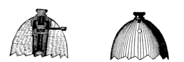
German Percussion Fuse.
Both percussion and time fuses are used in the shells of all calibres. The percussion fuse consists of a plunger having a fire-hole through the centre and surmounted by a pointed anvil. This is dropped into the fuse-hole of the shell, and hangs on a shoulder in the wall of the fuse-hole. Even with the point of the anvil a hole is bored through the wall of the shell horizontally, into which a pin is inserted whose inner end covers the anvil and keeps it from going forward. A gun-metal case screws into the end of the fuze-hole, and into this screws a small cap carrying the fulminating composition. When the gun is fired the centrifugal force throws the pin out, and when the projectile strikes the plunger rides forward against the fulminate and explodes it. The fulminate-cap and the pin are not inserted until the projectile is brought to the gun, the mouth of the fuse-hole being kept sealed by a wafer. The Krupp time-fuse consists of a gun-metal body which screws into the fuse-hole and has two chambers. The lower one, containing the blowing-charge, opens into the shell. It is solid to the rear, except a diagonal channel on one side which is pierced up and opens on a small table which carries the fuse-composition disc. The latter is circular and on the principle of the Bormann fuse, its exterior wall being marked for seconds and fractions. The upper chamber of the fuse is open at its upper extremity and closed at the lower, except several side channels leading to the composition disc. In the bottom of this chamber is a pointed anvil. The fuse-cap is ogival and screws over the tipper chamber, fitting tightly down on the composition disc. In this cap is a plunger loaded with fulminating composition at its lower end, and suspended by five small tenons. The composition is ignited by the percussion part of the fuse on firing. A safety-pin passes through the fuse-cap and plunger, and is withdrawn when the shell is brought to the gun.
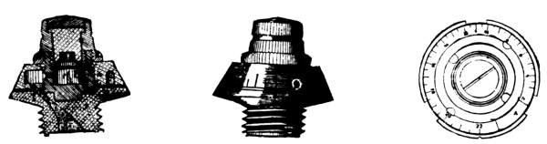
German Time-Fuse.
PRIMERS.
Friction primers are used altogether. These are of the same type as those used with English guns. (See English Ordnance.)
SIGHTS.
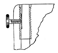
Sight-Bush and Clamp.
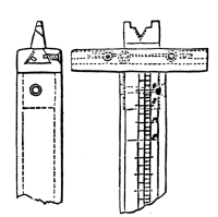
Rear-Sight.
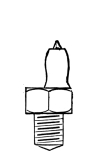
Front-Sight.
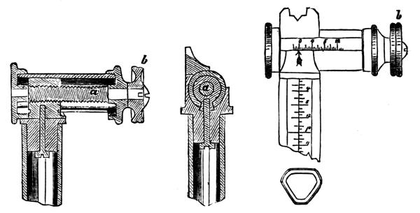
Rear-Sight for Light Guns.
The sights used with naval guns are all of the tangent pattern, and all except the boat-guns are provided with sights on both sides. The socket for the tangent-sight is bored through the breech-piece, the upper part having steel or bronze bushing and a clamp-screw passing through at right angles. The sight is cylindrical, with a flat rear surface on which is marked elevations to sixteenths of degrees. On the left cylindrical side, elevations for every 100 metres are marked for common shell, and on the right for chilled or steel shot. The head of the sight consists of a rectangular cross-head fastened to the top of the bar, in whose upper surface a swallow-tailed groove is cut in which travels the sight-notch. On the face of the cross-head, gradations of sixteenths of a degree corresponding to elevations are marked, and the sight-notch carries a small pointer. The gradations are marked each way so as to account for drift and deviation to the right or left. The forward sight is cylindrical, with a conical point, and screws into the trunnion-hoop. Sights for boat-guns differ in having gradations only on the rear face, and the sliding leaf works by an endless screw. These sights are all vertical. With some boat-guns, however, the tangent-sight is placed at a permanent angle of deflection, in which case there is no sliding leaf.
Italian Ordnance.
A = Calibre.
B = Over all.
C = Rifled Bore.
D = Powder Chamber.
Name, Nature, and Classification. A Length.
B C D
In. In. In. In.
Armstrong pattern Muzzle-loaders.
43 cm. 17 392 311.3 52
28 ” New Model 11 173 120.5 24.4
28 ” Old ” 11 173 119 26
25 ” No. 1 Long 10.1 173.2 119.1 26
25 ” ” Short 10.1 167.6 113.9 26
25 ” No. 2 10.1 156.1 111.1 14
22 ” 9 156.1 105.6 19.7
20 ” 8 130 88.6 15.8
Cast-iron Muzzle-loaders.
16 ” Wrought-iron Tube 6.5 142.1 104 13.8
16 ” 6.5 126.7 94.1 13.9
Armstrong Breech-loader.
12 ” 4.7 70.4 19.7
Bronze Breech-loader.
7.5 ” 2.95 70.1 52.4 10.2
Bronze Muzzle-loaders.
8 ” 3.4 45.3 9.8
8 ” 3.4 31.9 3.5
Cast-Iron Muzzle-loader.
12 ” 4.77 73.3 6.3
E = Number of Grooves.
F = Twist of Rifling.
G = Gun entire, including Breech-block.
H = Preponderance.
Name, Nature, and Classification. E F Weight. H
G
Calib. Lbs. Lbs.
Armstrong pattern Muzzle-loaders.
43 cm. 27 0/45 222,300 9,980
28 ” New Model 9 0/35 55,800
28 ” Old ” 8 0/45 55,800
25 ” No. 1 Long 7 0/40 40,100
25 ” ” Short 7 0/40 40,400
25 ” No. 2 8 55 27,000 620
22 ” 6 0/43 28,260
20 ” 6 45 15,680 805
Cast-iron Muzzle-loaders.
16 ” Wrought-iron Tube 6 42.5 11,440 1,065
16 ” 6 42.5 7,920 924
Armstrong Breech-loader.
12 ” 27 2,640 59.4
Bronze Breech-loader.
7.5 ” 12 48.6 596 79.2
Bronze Muzzle-loaders.
8 ” 6 25 726
8 ” 6 25 240
Cast-Iron Muzzle-loader.
12 ” 6 27 2,948
A = Weight of Carriages.
B = Height of Axis of Trunnions above Deck-level.
C = Steel.
D = Chilled.
E = Common.
F = Ordinary.
G = Saluting.
Name, Nature, and Classification. A B Projectiles.
Weight Complete. Bursting Charge.
C D E D E
Lbs. In. Lbs. Lbs. Lbs. Lbs. Lbs.
Armstrong pattern Muzzle-loaders.
43 cm. 2,000 37
28 ” New Model 17,820 52 528 528 200 5.7 26
28 ” Old ” 17,820 52 528 530 200 5.7 26
25 ” No. 1 Long 15,750 44 294 300 188 5 24
25 ” ” Short 15,590 46 294 300 188 5 24
25 ” No. 2 12,620 42 288 284 135 3.3 18
22 ” 12,620 42 248 252 99 2.2 19
20 ” 7,480 34 156 150 79 1.3 9.7
Cast-iron Muzzle-loaders.
16 ” Wrought-iron Tube 4,540 65 33 2.3
16 ” 1,287 66 33 3.3
Armstrong Breech-loader.
12 ” 35 2.6
Bronze Breech-loader.
7.5 ” 477.4 8 9 .5
Bronze Muzzle-loaders.
8 ” 587.4 9 9.25 .7
8 ” 176 9 4.4 .7
Cast-iron Muzzle-loader.
12 ” 550 26 22.6 3.1
D = Chilled.
E = Common.
F = Ordinary.
G = Saluting.
Name, Nature, and Classification. Powder Charge.
D E D E
Lbs. Lbs. Lbs. Lbs.
Armstrong pattern Muzzle-loaders.
43 cm. 471
28 ” New Model 95 95 66
28 ” Old ” 95 95 66
25 ” No. 1 Long 77 77 53
25 ” ” Short 77 77 53
25 ” No. 2 64 64 42
22 ” 60 60 37
20 ” 44 44 24
Cast-iron Muzzle-loaders.
16 ” Wrought-iron Tube 20 20 7 8
16 ” 7.7 8
Armstrong Breech-loader.
12 ” 5.5 2.2
Bronze Breech-loader.
7.5 ” 1.5 1.4
Bronze Muzzle-loaders.
8 ” 1.2 1.2
8 ” .7 1
Cast-iron Muzzle-loader.
12 ” 3.3 2.2
A = Chilled.
B = Common.
C = Penetration.
Name, Nature, and Classification. Initial Velocity. Working Effect. C
A B A B
Ft. Ft. Ft.Tons. Ft.Tons. In.
Armstrong pattern Muzzle-loaders.
43 cm. 1,584 34,550 22.8
28 ” New Model 1,312 1,312 6,300 6,300 12.1
28 ” Old ” 1,312 1,312 6,262 6,330 12.1
25 ” No. 1 Long 1,410 1,399 5,369 5,390 11.7
25 ” ” Short 1,410 1,399 5,369 5,390 11.7
25 ” No. 2 1,410 1,420 3,952 3,970 10
22 ” 1,476 1,476 3,731 3,790 10.3
20 ” 1,476 1,509 2,345 2,345 8.7
Cast-iron Muzzle-loaders.
16 ” Wrought-iron Tube 1,525 1,066
16 ” 1,026 483
Armstrong Breech-loader.
12 ” 1,368 457
Bronze Breech-loader.
7.5 ” 1,312 97.5
Bronze Muzzle-loaders.
8 ” 1,040 63.4
8 ” 764 33.8
Cast-iron Muzzle-loader.
12 ” 1,095 12
The standard Italian naval ordnance is the Armstrong muzzle-loader. There are some batteries of breech-loaders of the French type, and now that the Armstrong 100-ton gun has become a part of the standard ordnance, the government have ordered them made breech-loading with the Armstrong breech mechanism. The guns are to be provided with arrangements for both breech and muzzle loading. With the breech-loading, as the block is turned to unlock it, a grip on the end of a hydraulic piston in rear takes in a slot in the block, and when the latter is unlocked, a movement of the piston to the rear withdraws it from the gun to a small car having a transverse motion by which the block is carried sideways so as to unmask the bore. An iron cylinder is then inserted and pushed up to the rear of the powder-chamber as a loading-plate, guarding the screw-threads from injury. The charge, being raised by a hydraulic press in the usual manner, is forced home by a hydraulic rammer, and the breech-block is closed by its car and piston. The Gatling gun is used, and there has been an attempt to introduce the Albertini machine-gun, which is used in the army. Although of native manufacture, it has not as yet been received with much favor, being still too complicated in its mechanism, although the instrument is not as yet perfected.
Greek Ordnance.
The armament of the Greek Navy is exclusively of Armstrong muzzle-loaders.
Dutch Ordnance.
The standard naval ordnance of Holland is at present the Krupp type. Many of their vessels have batteries of Armstrong muzzle-loaders, and there are a few Finspong guns. The Hotchkiss machine-gun has been adopted for torpedo defence. (See page 305.)
Japanese Ordnance.
The standard Japanese naval ordnance is the Krupp. There are a few batteries of Armstrong muzzle-loaders, but none are now purchased.
Swedish Ordnance.
A = Calibre.
B = Over all.
C = Rifled Bore.
D = Powder Chamber.
E = Number of Grooves.
F = Twist of Rifling.
G = Gun complete, including Breech-block.
H = Breech-block.
Name, Nature, and A Length. E F Weight.
Classification. B C D G H
In. In. In. In. Cal. Lbs. Lbs.
Rifled Breech-loaders, cast-iron with steel hoops.
27 cm 10.8 210 162 30.3 5 29.2 52,088 770
24 ” 9.4 179 133 26.6 5 29.3 31,800 528
16 ” 6.6 135 89.5 16.8 5 29.8 12,000 170
Cast-iron Muzzle-loader, Rifle.
12 ” 4.6 102 97 13.6 4 40 4,200
Cast-iron Smooth-bores.
15 in 15 146 43,000
9 ” 9 158 38,000
Norwegian Ordnance.
Armstrong Muzzle-loaders.
27 cm 10.5 162 110.6 20.5 8 55 40,500
27 ” 10.5 176 120 25 8 55 43,400
27 ” 10.5 206 47,700
20 ” 8 130 85.7 18.8 6 50 16,700
Palliser Muzzle-loaders.
16 ” 6.6 139 85.7 18.5 3 34.1 11,000
15 ”
Krupp Breech-loaders.
26 ” 10.2 225 160.5 34 60 45 48,400 1,960
15 ” 5.9 152 112 22.6 36 45 8,800 304
A = Preponderance.
B = Upper Carriage.
C = Slide.
D = Height of Axis of Gun above Deck-level.
E = Chilled.
F = Common.
Swedish Ordnance.
Name, Nature, and Classification. A Carriage. Projectiles.
B C D Complete Weight. Bursting Charge.
E F E F
Lbs. Lbs. Lbs. In. Lbs. Lbs. Lbs. Lbs.
Rifled Breech-loaders, cast-iron with steel hoops.
27 cm 127 23,076 23,076 49 475 396 23.2
24 ” 220 5,370 45 317 220 9.3
16 ” 403 2,105 2,200 40 107 76.5 3.7
Cast-iron Muzzle-loader, Rifle.
12 ” 85 2,105 900 41 34 2.2
Cast-iron Smooth-bores.
15 ” 253 31 430 340 14
9 ” 53 31 150 112 5.8
Norwegian Ordnance.
Armstrong Muzzle-loaders.
27 cm 1,340 6,720 28 385 308 6 21
27 ” 440 7,600 8,000 38 385 308 6 21
27 ” 403
20 ” 761 7,000 7,000 39 149 149 1.76 10.1
Palliser Muzzle-loaders.
16 ” 246 1,880 2,150 43 82.5 3.3
15 ” 246 1,000 2,300 43 58 3
Krupp Breech-loaders.
26 ” 756 20,608 20,608 52 462 380 59.4 21
15 ” 160 5,600 5,600 41 86 70 1.1 5
A = Chilled.
B = Common.
C = Penetration.
Swedish Ordnance.
Name, Nature, and Classification. Powder Charge Initial Velocity Working Effect C Remarks.
A B A B A B
Lbs. Lbs. Feet. Feet. Ft. Tons Ft. Tons In.
Rifled Breech-loaders, cast-iron with steel hoops.
27 cm 98 66 1,364 6,153 12 Finspong Rifles.
24 ” 59.4 37.4 1,322 1,476 3,763 3,333 10
16 ” 23.3 17.6 1,377 1,591 1,414 1,347 7.36
Cast-iron Muzzle-loader, Rifle.
12 ” 6.5 4.4 1,456 509
Cast-iron Smooth-bores.
15 in. 50.1 35 1,213
9 ” 24.8 17.6
Norwegian Ordnance.
Armstrong Muzzle-loaders.
27 cm. 66 38.5 1,302 1,148 4,541 3,156 10.5
27 ” 71.5 38.5 1,371 1,148 5,032 3,156 11
27 ”
20 ” 29.7 19.8 1,364 1,148 1,938 1,360 7.9
Palliser Muzzle-loaders.
16 ” 22 11 1,138 742 7.1
15 ”
Krupp Breech-loaders.
26 ” 99 81.4 1,584 1,584 7,933 6,644 14
15 ” 18.7 18.7 1,590 1,640 1,528 8
The Norwegian ordnance is both smooth-bore and rifled, the smooth-bore guns being of the Rodman (see page 283) and the rifles of the Krupp style. The Swedes manufacture their own breech-loaders, having chosen for their standard the French type of cast-iron body reinforced by steel hoops. These guns, known as the Finspong breech-loaders, have proved very satisfactory, the Swedish cast-iron being second only to American in excellence. The breech-blocks and steel hoops for these guns are all made in France. Two types of machine-guns, which have found general favor in Europe, are of Swedish invention.
The Nordenfeldt Machine-Gun.
This gun, which has been experimented with in the English Navy, is intended as a defence against torpedo-boats. It has four barrels placed in line, having a calibre of one inch, to fire a half-pound steel projectile. The projectiles are placed in guides behind the rear of the barrels, and by the movement of a lever are sent into the chamber, fired, and the empty shell extracted. Gearing worked by hand-wheels gives elevation and direction. The fire is rapid from this gun, and the results have been excellent for penetration. Weight of the gun complete, about 1000 pounds.
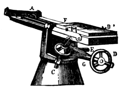
The Palmcrantz Machine-Gun.
The Palmcrantz mitrailleuse is a machine-gun for firing small-arm ammunition. It has ten barrels placed side by side and secured in a frame, the rear ends of the barrels being screwed into a single bar-transom, behind which the lock mechanism is placed in a flat rectangular box. The system is mounted on a swivel in such a manner as to give it free motion for elevating and depressing or sweeping. An eccentric cam attached to the crank-axle can be thrown into gear, by means of which the barrels are given an automatic sweep through a small arc. The whole gun is compact and light. Each barrel has a separate feeder, so that the velocity of discharge is very great, the barrels being fired in succession.
Russian Ordnance.
A = Calibre.
B = Length over all.
C = Number of Grooves.
D = Twist of Rifling.
E = Weight of Gun, including Breech-block.
F = Preponderance.
Name, Nature, and Classification. A B C D E F
In. In. Cal. Lbs. Lbs.
Krupp Russian pattern steel Breech-loaders.
Finished.
12 in. 12 240.8 36 89,173 1,958
11 ” 11 219 36 70 57,280 0
9 ” 9 180 32 60 33,150 440
9 ” 9 156 32 60 29,920 748
8 ” 8 175 30 60 19,820 440
Unfinished.
6 ” 6 140 24 45 9,370 352
8 ” 8 175 30 60 17,570 792
6 ” 6 146 24 45 10,090 1,078
9 pdr. 4.2 16 1,738
4 ” 3.4 70 12 40 792 88
Bronze Rifled Muzzle-loaders.
8 pdr. 4 1,650
4 ” 3.4 809
4 ” 3.4 865
American pattern cast-iron Smooth-bore Muzzle-loaders.
20 in. 20 96,360
15 ” new 15 180 72,160 0
15 ” old 15 170 43,340 1,078
10¾ ” 10.75 168 26,180 1,333
60 pdr. No. 1 7.6 135 10,780 792
60 ” ” 2 7.6 7,040
36 ” ” 1 6.8 7,040
36 ” ” 2 6.8 5,610
36 ” ” 3 6.8 4,590
36 ” ” 4 6.8 4,240
30 ” ” 1 6.4 6,864
30 ” ” 2 6.4 5,214
30 ” ” 3 6.4 4,330
30 ” ” 4 6.4 1,770
G = Weight of Upper Carriage.
H = Steel.
I = Chilled.
J = Common.
Name, Nature, and Classification. G Projectiles.
Complete Weight.
H I J
Lbs. Lbs. Lbs. Lbs.
Krupp Russian pattern steel Breech-loaders.
Finished.
12 in. 649 644
11 ” 10,604 495 462 439
9 ” 270 264 267
9 ” 270 264 267
8 ” 4,686 180 191 172
Unfinished.
6 ” 3,508 96 85.4 84
8 ” 4,868 180 191 182
6 ” 3,322 96 85.4 84
9 pdr. 693 24
4 ” 739 14
Bronze Rifled Muzzle-loaders.
8 pdr. 666 26
4 ” 603 11.5
4 ” 603 Cast-iron Round Shot. 13.5
American pattern cast-iron Smooth-bore Muzzle-loaders.
20 in. 1,000 1,000
15 ” new 440 440 373
15 ” old 6,270 440 440 373
10¾ ” 160 160
60 pdr. No. 1 2,220 57.7 57.7 43
60 ” ” 2 1,518 57.7 57.7 43
36 ” ” 1 1,518 40 40 29
36 ” ” 2 1,210 40 40 29
36 ” ” 3 990 40 40 29
36 ” ” 4 790 40 40 29
30 ” ” 1 1,408 32 32 26
30 ” ” 2 1,188 32 32 26
30 ” ” 3 1,528 32 32 26
30 ” ” 4 32 32 26
A = Steel.
B = Chilled.
C = Common.
D = For Steel and Chilled Shot.
E = Common Shells.
F = Ordinary.
G = Saluting.
Name, Nature, and Classification. Projectiles. Powder Charge.
Bursting Charge. D E F G
A B C
Lbs. Lbs. Lbs. Lbs. Lbs. Lbs. Lbs.
Krupp Russian pattern steel Breech-loaders.
Finished.
12 in. 16 121 58.5
11 ” 12 7 13.5 82.5 41.2 9
9 ” 7 4.5 9.5 47 23.4 7.2
9 ” 7 4.5 9.5 43 23.4 7.2
8 ” 5 2 6.2 28.5 14.2 7.2
Unfinished.
6 ” 1.8 3 18 10.8 4.5
8 ” 5 2 6 22.5 14.2 7.2
6 ” 1.8 3 14.4 10.8 4.5
9 pdr. 1 2.7 2.5 2.7
4 ” .5 1.5 1.5
Bronze Rifled Muzzle-loaders.
8 pdr. 1.5 3.6 3.6 3.6
4 ” .8 1.5 1.5 1.5
4 ” 1 Cast-iron Round Shot. 2 1.8 1.8
American pattern cast-iron Smooth-bore Muzzle-loaders.
20 in. 117
15 ” new 10.75 67.5 45 27 9
15 ” old 10.75 67.5 45 27 9
10¾ ” 36 9
60 pdr. No. 1 1.8 14.5 10 4.5
60 ” ” 2 1.8 10.8 2.6 4.5
36 ” ” 1 1 8 2 3.6
36 ” ” 2 1 8 2 3.6
36 ” ” 3 1 6.2 1.6 8.6
36 ” ” 4 1 5.5 1.4 8.6
30 ” ” 1 .8 9 2.3 2.7
30 ” ” 2 .8 6.7 1.7 2.7
30 ” ” 3 .8 5 1.2 2.7
30 ” ” 4 .8 3.5 .9 2.7
A = Steel.
H = Working Effect.
I = Penetration.
Name, Nature, and Classification. Initial Velocity. H I
A
Feet. Ft. Tons. In.
Krupp Russian pattern steel Breech-loaders.
Finished.
12 in. 1,446 9,408 14.1
11 ” 1,205 5,844 11.6
9 ” 1,341 3,365 9.8
9 ” 1,276 3,043 9.3
8 ” 1,404 2,463 9.0
Unfinished.
6 ” 1,335 1,188 7.1
8 ” 1,246 1,938 7.8
6 ” 1,207 972 6.4
9 pdr. Common 1,049 183
4 ” Common 1,003 96
Bronze Rifled Muzzle-loaders.
8 pdr.
4 ” Common 1,000 77
4 ”
American pattern cast-iron Smooth-bore Muzzle-loaders.
20 in. 1,118 8,581
15 ” new 1,184 4,263
15 ” old 971 2,872
10¾ ”
60 pdr. No. 1
60 ” ” 2
36 ” ” 1
36 ” ” 2
36 ” ” 3
36 ” ” 4
30 ” ” 1
30 ” ” 2
30 ” ” 3
30 ” ” 4
The standard type of Russian ordnance is the Krupp breech-loader, manufactured in their own workshops, and slightly modified in some few details of guns and carriages. Some of their monitors are armed with the Rodman type of 15-inch smooth-bore. During the first period of the development of rifled guns the Russians adopted the Armstrong muzzle-loader, and shortly afterward they passed to the French breech-loader, there being still several armaments of these types in the wooden fleet; but all types have been superseded by the Krupp. The circular iron-clads having their guns firing en barbette, are worked on depressing carriages of Russian invention.
The Razkazoff Depression-Carriage.
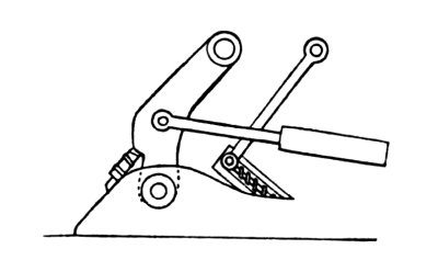
This carriage consists of a heavy bed-plate, at the forward end of which is a heavy solid axle forming a turning-point for two solid cast arms, the upper ends of which form seats for the trunnions. Connected to these arms are the piston-rods of hydraulic recoil cylinders. The breech of the gun is supported by auxiliary arms, the bottom rests of which are mounted on screws in such a manner that they may be traversed through short lengths, thus elevating or depressing the gun. When the gun is down in its loading position these arms may be freely traversed, and the desired elevation be thus attained before raising the gun for firing. Both the Palmcrantz and the Hotchkiss machine-guns are used.
Peruvian Ordnance.
The naval ordnance of Peru consists of a few smooth-bores of the Rodman type and some Armstrong muzzle-loaders of the original type. They also have two or three Whitworth muzzle-loaders. The machine-guns are Gatlings.
Portuguese Ordnance.
The Portuguese Navy has a few Krupp breech-loaders, but the wooden fleet is for the greater part armed with Armstrong muzzle-loaders.
Spanish Ordnance.
The greater part of the Spanish fleet is armed with Armstrong muzzle-loaders, but medium-calibred steel guns of the French type are now manufactured in their own government workshops, some of which have been introduced into the navy, and it is supposed that at least for medium calibres this type will be the standard. There are some Krupp armaments, but these are exceptional. The Gatling machine-gun is used.
Turkish Ordnance.
The greater part of the ordnance of the Turkish fleet is of the Armstrong muzzle-loading pattern, although there is a preference for Krupp armaments, which are used to replace the original type of Armstrong guns. The Gatling machine-gun is used.
European Systems.
Of the breech-loading systems of Europe there are at present but two distinct types in use—the French and the Krupp—the latter being the one at present most fully represented, it being the standard ordnance of Germany, Russia, Austria, Denmark, and Holland.
The French type is the standard of France, Spain, Sweden, and, as may now be claimed, Italy. Armstrong, whose artillery is almost as fully represented as Krupp’s, has adopted the French type, and this will in all probability make this type the standard in those countries who purchase guns instead of manufacturing them.
The muzzle-loading types were abolished by all the manufacturing nations of Europe except England by 1864, although the prestige of Armstrong’s ordnance has kept up the supply to the smaller nations to the present time. This ordnance has been steadily growing in disfavor, and the latest development in rifled ordnance (enlarging the powder-chamber) will probably lead to its disuse.
United States Ordnance.
A = Length of Bore.
B = Calibre.
C = Number of Grooves.
D = Twist of Rifling.
E = Weight.
Name, Nature, and Classification. Gun. F G
A B C D E
In. In. Feet. Lbs. Lbs. Lbs.
Muzzle-loading Rifles.
8 inch converted 136 8 15 40 17,350 3,790 3,710
100-pdr. Parrott 130 6.4 9 0/19 9,700 1,300 Directing Bar
60-pdr. ” 105 5.3 7 0/15 5,400 1,970 ”
30-pdr. ” 4.2 5 0/12 3,550 1,970 ”
20-pdr. ” 3.7 5 0/10 1,750 802 ”
20-pdr. Dahlgren 65.6 4 3 12½ 1,350 802 ”
12-pdr. bronze 55 3.4 3 10 880 482 Boat Carriage
Breech-loading Rifles.
80-pdr. converted 6.4 9 0/19 10,166 1,300 Directing Bar
60-pdr. ” 5.3 7 0/15 5,270 1,970 ”
30-pdr. ” 4.2 5 0/12 3,428 1,970 ”
20-pdr. bronze, converted 4 6 12½ 1,340 832 Boat Carriage
20-pdr. converted 3.7 5 0/10 1,740 826 ”
7-pdr. bronze, heavy 3 16 7½ 535 500 ”
7-pdr. ” light 3 16 7½ 350 450 ”
Smooth-bores. Weight of Shot. Lbs.
15-inch 146 15 450 43,000 18,000 Turret Carriage
11-inch 131 11 166 16,000 3,790 3,710
9-inch 107 9 90 9,000 1,300 Marsilly
8-inch 96 8 65 6,500 860 ”
32-pdr. 92 6.4 32.5 4,500 735 ”
24-pdr. bronze 58 5.8 Shell Guns. 1,310 730 ”
12-pdr. ” heavy 55 4.6 760 Boat 482 Field 487
12-pdr. ” light 50 4.6 430 233 381
A = Weight of Shell.
B = Charge of Powder in Shell.
C = Powder Charge.
D = Initial Velocity.
E = Muzzle Energy.
Name, Nature, and Classification. A B C D E
Lbs. Lbs. Ozs. Lbs. Feet. Foot Tons.
Muzzle-loading Rifles.
8-inch converted 180 10 0 35 1,450 2,627
100-pdr. Parrott 100 3 11 15 1,080 810
60-pdr. ” 48 2 2 6 1,320
30-pdr. ” 29 1 8 3¼
20-pdr. ” 18 0 13 2
20-pdr. Dahlgren 18 1 0 2
12-pdr. bronze 12 0 8 1
Breech-loading Rifles.
80-pdr. converted 80 3 11 15 1,250
60-pdr. ” 50 6
30-pdr. ” 30 3½
20-pdr. bronze, converted 18 0 8 2
20-pdr. converted 20 2 1,070
7-pdr. bronze, heavy 7 1 1,087 63
7-pdr. bronze, light 7 ¾ 1,087 63
Smoth-bores.
15-inch 352 13 0 100 1,600 7,997
11-inch 136 6 0 30 1,062 1,300
9-inch 74 3 0 18 1,820 847
8-inch 58 1 11 7
32-pdr. 27 0 14 6
24-pdr. bronze 23 1 0 2
12-pdr. ” heavy 12 1 0 1
12-pdr. ” light 12 1 0 ½
GUNS.
In the United States Navy both smooth-bores and rifles are used, and of the latter both muzzle and breech-loaders.
Smooth-Bores.
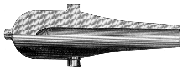
15-inch Rodman Gun (Smooth-Bore).
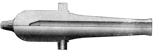
9-inch Dahlgren (Smooth-Bore).
The smooth-bore guns used form a complete range of calibres from the 15-inch to the 6½-inch. The turret-guns, which are exclusively of the 15-inch pattern, are of the Rodman type of construction, of cast-iron, being cast on a core and cooled from the interior. The exterior surface shows no sharp angles and no muzzle-ring, the general shape being that of a bottle with a rounded base. The chamber of the gun is of two types, cylindrical and conical, in accordance with different dates of fabrication. The 11-inch guns are used exclusively for pivot-guns of first and second class corvettes, and it is this calibre that is being converted into 8-inch rifles, the intention being to so transform all of this type. These guns are of the Dahlgren type of construction, being similar in shape to the 15-inch (with the exception of having a swell at the muzzle), but solid cast. These guns all have conical chambers. The 9 and 8 inch and 32-pdr. are broadside-guns, and are similar in construction to the 11-inch. The 24-pdr. and two classes of 12-pdrs. are of bronze, having a conical exterior surface. These guns are used as light upper-deck guns and boat-guns.
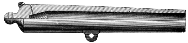
12-pdr. Bronze (Smooth-Bore).
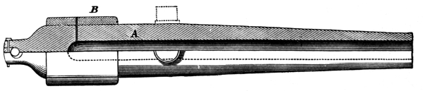
100-pdr. Parrott M. L. R.
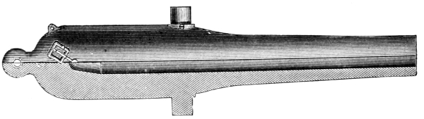
20-pdr. Bronze M. L. R.
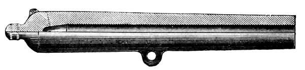
12-pdr. Bronze M. L. R.
Rifled Guns.
The muzzle-loading rifled guns are of three patterns.
1st. The 8-inch converted. These guns are all converted from the 11-inch smooth-bore on the Palliser system (see page 217), the length of bore being slightly increased by cutting back at the breech.
2d. The Parrott type, a compound gun consisting of a cast-iron body with a coiled wrought-iron hoop over the powder-chamber. These guns were introduced into the service in 1860, contemporaneously with the first development of rifled guns in Europe.
As early as 1862, guns of this type with a calibre of eight inches were in active service, being at that time as powerful as any guns in the world. The 8-inch calibre has never been extensively used in the service, and is at present obsolete.
3d. The Dahlgren type of bronze muzzle-loaders. The 20-pdr. gun of this type is similar in shape to the general smooth-bore type, slightly modified. The light calibres are similar to their corresponding smooth-bores.
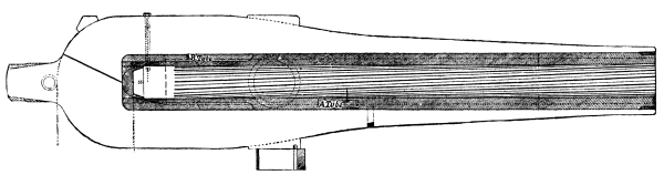
8-inch Converted M. L. R.
Breech-Loaders.
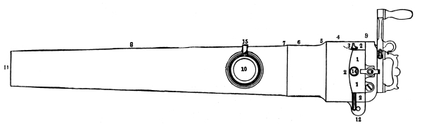
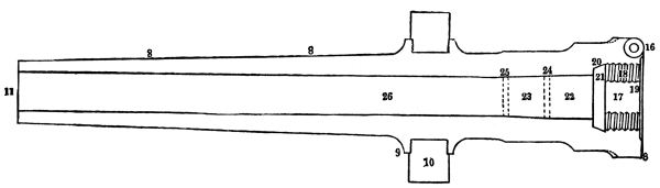
3-inch Boat-Gun (R. B. L.).
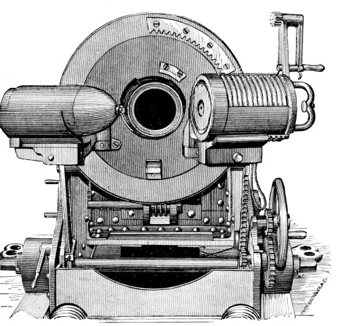
The breech-loaders with the exception of the bronze and steel boat-guns are as yet entirely converted from the muzzle-loaders of the Parrott type. In this conversion, the coiled hoop is removed, the cascabel is cut off to the powder-chamber, and the rear end of the bore as far forward as the trunnion is reamed out for the insertion of a steel tube, having a heavy screw-thread at its rear end by which it is secured in the casing. The old rifling is then carried through this tube, leaving the calibre unchanged. The coiled hoop is replaced by another of similar type, but covering a longer space. The breech mechanism is of the French type, with Broadwell steel gas-check fixed in its seat in the gun. The breech-block is provided with a steel nose-plate of the diameter of the face of the block, and having a copper ring countersunk in its forward face to form a bearing surface against the rear of the gas-check. The nose-plate is secured to the block by a long tenon which passes through the axis of the block and is secured by a nut at the rear. The vent is bored axially through this tenon, and is of two types, corresponding to date of fabrication, for preventing back-fire. In the first, a small steel plate covers the forward end of the vent, being loosely secured, so that on firing the flame escapes past the edges of the plate, but the back pressure holds the plate close over the vent; the action being precisely similar to that of an ordinary valve. In the other type, the forward part of the vent is reduced in size until just large enough to give free passage to the flame, giving it a needle-point, which causes the flame to pierce well into the cartridge. The back pressure is neutralized in this manner, as it reacts before the forward flame pressure is relieved. It is intended to so modify the firing arrangement as to use percussion primers, the gun-lock forming the mask to the vent. The crank is double, there being a vertical arm having at its upper extremity a crank and a pinion working in a rack on the face of the breech. The swinging tray for the breech-block is hinged at the right side of the breech, while at the left side is hinged a loading-tray having a sliding guard on it. The projectile being placed on this guard and the tray swung around to face the bore, on pushing forward the projectile the guard also enters the breech-block seat, bringing up against the gas-check, and thus guarding both the check and the screw-threads. In the boat-guns there is no loading-tray, the remainder of the breech mechanism being of the same type. Boat-guns are both of steel and bronze, being in both cases made of a single block.
Grooves.
The grooves are of two types. Those for the Parrott and converted guns are of the plain rectangular type, the rule for their number and size being that they shall be uneven in number to bring a land opposite a groove; lands and grooves shall be equal in width, and grooves for all calibres shall be the same depth—¹/₁₀₀ of an inch. Increasing twist. The Dahlgren type of groove is similar to the modified French groove (see plate, page 187), there being three only of a regular twist. These grooves are found only in the Dahlgren muzzle-loading bronze boat-guns.
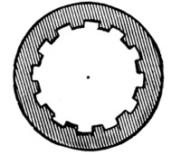
Parrott Groove.
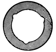
Dahlgren Groove.
CARRIAGES.
Naval gun-carriages are built of plate-iron, although there are still a few wooden carriages and slides for pivot-guns. Breechings are used with broadside-carriages, except in the directing-bar type.
Boat-Carriages.
As yet the designs for an iron boat-carriage for the breech-loading gun are not finished. The wooden carriage in use consists of a double wooden slide, the bed, or lower slide, having pivot-centres in front and rear and being slotted through the centre for the compressor. The upper slide traverses freely on the lower one, having a piece projecting from its lower face into the slot in the lower slide to act as a guide. A second heavy piece, used as a compressor, travels along the lower face of the slot, and is held in position by screw-handles working on threaded shafts which are tightened or loosened readily by hand. The upper slide holds the trunnion-rests, which are made in a single casting with a bottom plate to bolt on the slide.
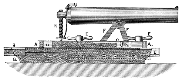
Wooden Boat-Carriage.
Field-Carriages.
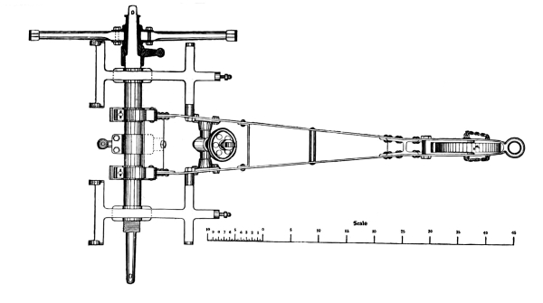
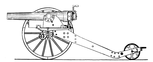
The field-carriages are of two types, both of iron. That for the muzzle-loader consists of a single bar to which the axle is bolted and stayed. To its lower end is bolted an iron box for a trail-wheel and a socket for a directing handspike. A small seat for the elevating-screw is bolted at its middle on top, and at the forward end is a light iron frame for holding two ammunition-boxes. The field-carriage for the breech-loader consists of two plate-iron brackets connected by the axle and three transoms. The lower part expands into a box for the trail-wheel, and the end is finished in a loop for a drag-rope. At the forward end is a lug for attaching a caisson, and a frame on the axle outside of the brackets on each side for ammunition-boxes. The elevating-screw works in a pivoting screw-box. It will be noticed that the breech-loader has trunnions, while the muzzle-loader has only a lug, making the forward ends of the two carriages different in construction.
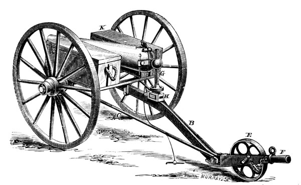
Iron Field-Carriage for Muzzle-Loaders.
Broadside Marsilly Carriage.
The Marsilly or rear-chock carriage is the type used with the broadside smooth-bore guns. It consists of two plate-iron brackets with a transom across the front ends and a bed-plate in the rear, giving a support for the elevating-screw, and being provided with two brass friction-shoes resting directly on deck. Holes are cut in the brackets to lighten them. A wooden breast-sweep is bolted to the transom, and there are four bolts for hooking tackles, one at each end and one at the rear of each bracket. This carriage differs from European ones in the point of not having the breeching attached to it; the latter is secured to the gun.
Broadside Directing-Bar Carriage.
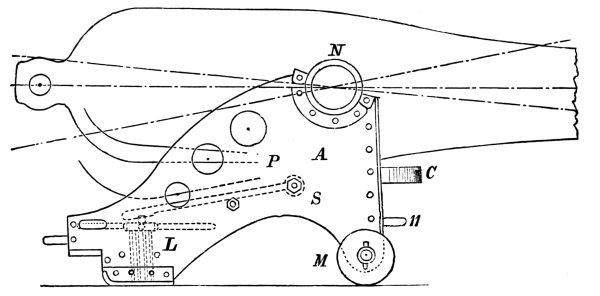
Broadside Marsilly Carriage. (Elevation.)
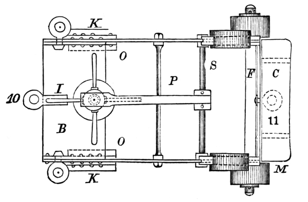
Broadside Marsilly Carriage. (Plan.)

DIRECTING BAR CARRIAGE FOR 60 Pdr.
(With Circular Brake Compressor.)
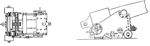
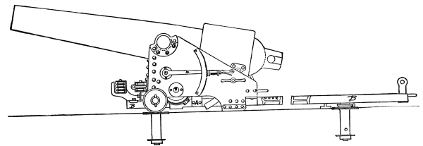
The directing-bar carriage is a broadside-carriage which combines the compactness of broadside types with the advantages of pivoting and checking recoil by friction instead of breechings. The top carriage is similar in type to the Marsilly, differing only in its attachments. Instead of using an elevating-screw (which with breech-loaders of medium calibre is unsafe), elevation is secured by geared racks. A rack is secured to each side of the gun and travels in guides in a similar manner on both sides; whilst, however, there is a clamp to each rack, there is but one hand-wheel for elevating, on the right side of the carriage. Just in rear of the truck-axle, a heavy axle is secured in the brackets, carrying on its centre a large cogged wheel, and just inside the left bracket a friction-drum with a gun-metal friction-band worked by a lever outside the bracket. The lever is held in any desired position by a rack, thus regulating compression. A stationary double block is secured to the transom, and a single bolt to the rear of the bed-plate, for convenience in hooking a tackle. The directing-bar consists of a long I iron having a pivot-centre near each extremity and eye-bolts at each end for hooking training-tackles. A treble block fixed at its forward end serves with the double block on the carriage for reeving an out-tackle. Along the centre of the bar a metal rack is bolted, in which the cogged wheel of the carriage travels. About three quarters of the distance to the rear are secured two railroad buffers, which may be shifted or removed at will. The carriage rests with its trucks and chocks on deck; when running in and out the chocks may be lifted from the deck on a roller handspike, and in shifting from one port or pivot to another the carriage may be run over one of the pivot-centres and then lifted with the bar entirely clear of the deck.
Iron Pivot-Carriage and Slide for 11-inch Smooth-Bore.
The carriage consists of two plate-iron brackets with one transom and two bottom plates connected by angle-irons to the brackets. The forward trucks are permanently in action, the rear ones being mounted on eccentric axles. At the rear of the brackets are loops for the in and out tackles, and secured to the rear bed-plate are loops for a preventer-breeching. Two projecting lips protrude from the forward bed-plate beyond the brackets, forming seats for a screw-compressor. The slide is made up of two heavy double T bars connected by bottom plates and rods. It is mounted on eccentric rollers, and both the forward and rear pivot-centres are in the bed-plates. The compressors (one on each side) are of the ordinary screw-press form, composed of a wrought-iron frame having a lip on its inner lower side which takes under the slide-bars, whilst a screw in the top of the frame seats on the projections of the carriage. This type of slide and carriage is going out of use.
Iron Pivot-Carriage with Central Recoil Check.
This carriage is the same in general principle as the ordinary pivot-carriage, the main modification being in the arrangement for checking recoil. A worm-shaft, attached to the transom of the carriage and worked by a hand-wheel outside the left bracket, gears in a large cogged wheel just outside the transom. This wheel has at the lower end of its axle a screw-sleeve operating a friction-plate which seats against two heavy bars secured to the slide. Railroad buffers are also fixed at each end of the slide.
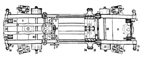
Central Recoil-Check Carriage.
Geared Broadside-Carriage and Slide with Hydraulic Recoil Check.
The carriage is very low, its bottom plates coming down inside the slide-rails, which are given a slope to the front. The slide is centre-port pivoting. The carriage is run out and in either by tackles or gearing. For the latter, long screw-shafts are fixed outside of the slide-rails on each side, geared by mitre-gearing to large cogged driving-wheels on the rear of the slide. A long lever is pivoted in wake of the trunnion-sockets, carrying at its lower end a half screw-sleeve. By heaving out on the lever, the sleeve engages in the screw-shaft and the gun is drawn in or out. The recoil cylinder is of the ordinary type, but provided with a circulating pipe and balanced valve by which the oil passes from one end to the other. The valve may be regulated for any desired amount of recoil. The training-gear is of the ordinary type, working a longitudinal shaft having on its outer end a cogged wheel to gear in a metal rack just inside of the rear slide-rollers.
Ericsson’s Broadside-Carriage and Slide with Friction Recoil.[8]
The recoil arrangement of this carriage is made up of two plates operated by a lever, and jamming between them a flat plate attached to the carriage. The carriage is run in and out by gearing, the driving-wheel engaging in racks inside the slide-rails. The training-gear is of the ordinary type, but gears directly into the slide-rollers, whose middle sections are cogged, the middle section of the circle or races being cut in a rack.
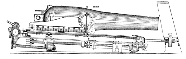
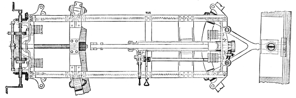
Geared Carriage and Slide with Hydraulic Recoil.
Ericsson’s Turret-Carriage.
The slide of the turret-carriage consists of two bars built into the turret. The carriage is made of double plate-iron worked on a frame. The compressor is the original of the Elswick compressor (see page 201), working on the same principle. The gun is run in and out by means of a large cogged driving-wheel gearing in a rack underneath the slide.
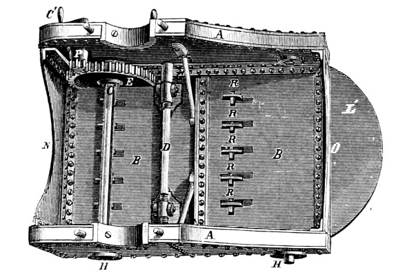
Ericsson’s Turret-Carriage. (Top.)
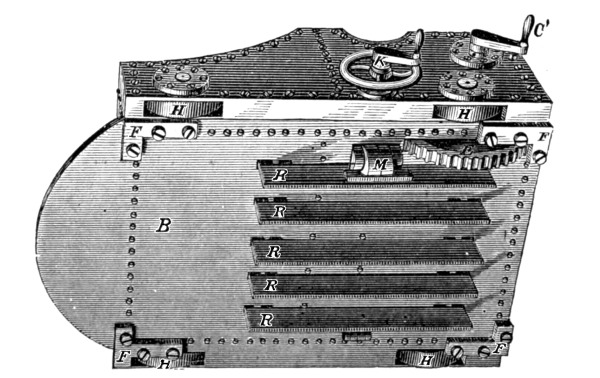
Ericsson’s Turret-Carriage. (Bottom.)
Friction-Drum Recoil-Check Carriage.
The carriage and slide are similar to those of the 11-inch iron pivot-carriage, except with regard to the recoil check, which is exactly the same in principle as that of the directing-bar carriage.
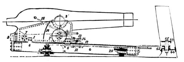
Ericsson’s Friction Recoil Carriage.
GUNPOWDER.
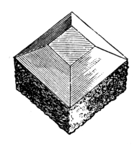
Cubical Powder.
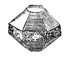
Hexagonal Powder.
Gunpowder is classed in accordance with its size of grain as follows:
Hexagonal Cubical not less than 70 nor more than 75 grains to the pound.
Mammoth ” ” 0.5 ” ” 1 inch measurement.
Rifle ” ” 0.3 ” ” 0.5 ” ”
Cannon ” ” 0.1 ” ” 0.3 ” ”
Torpedo ” ” 0.1 ” ” .15 ” ”
Small-arm ” ” 0.05 ” ” .06 ” ”
Shell ” ” .02 ” ” .06 ” ”
PROJECTILES.
The projectiles used with both smooth-bores and rifles are shot, shell, shrapnel, and case-shot.
All smooth-bore projectiles are of cast-iron.
All rifle projectiles except the 8-inch shot are common cast-iron; the shot are chilled-headed.
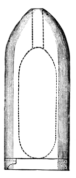
100-pdr. Parrott-Shell.
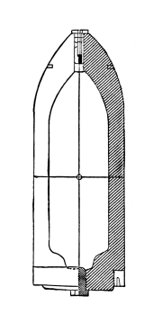
8-inch Shell.
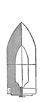
8-inch Shot.
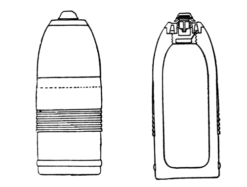
8-inch B. L. Shell.
Rifled projectiles for the boat-guns (B. L.) are provided with rotating grooved belts cast on them. They also have a rear centring ring. The rotating-rings for the larger calibres are brass rings screwing on the base of the projectile, and having an expansion groove or cup on the rear end. In the Parrott projectiles the ring is cast on the base around a heavy dovetailed score, having jogs to prevent the ring turning on the base of the shell.
The shrapnel for the boat-guns is of the simplest description, having a thin shell and a central powder-chamber throughout its length. Shrapnel for the heavy calibres is similar to the English type. Case-shot is of the ordinary construction.
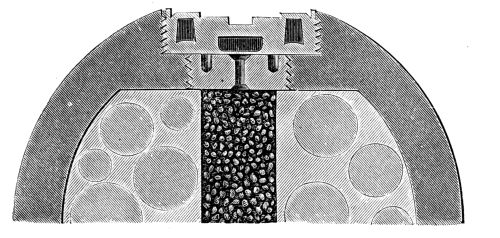
12-pdr. Smooth-Bore Shrapnel.
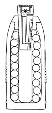
3-inch B. L. Shrapnel.
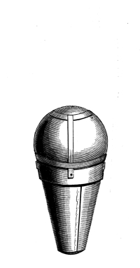
Fixed Charge for Boat-Gun. (Shell and Cartridge.)
FUSES.
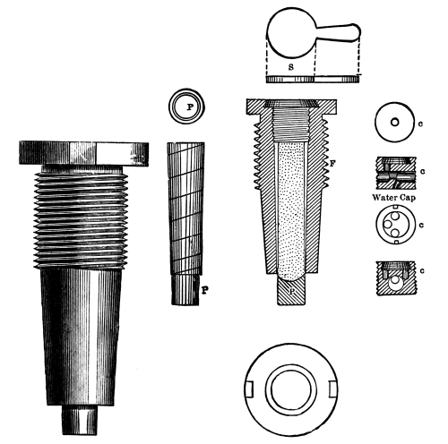
Navy Time-Fuse.
The fuses used in the navy are both time and percussion. There are three types of time fuses. The navy time-fuse, used in rifled and smooth-bore projectiles, consists of a brass fuse-case pierced by a centre hole, the bottom of which is closed by a small leaden plug simply jammed into place, called a safety-plug. On the top of this is the column of fuse composition driven in a paper case. Over this screws a small metal plug, called a water-cap, having angular passages cut through it to prevent the passage of water to the flame. These holes are filled with igniting composition. Over the water-cap is secured a leaden patch, sealing the fuse. This patch is torn off when the projectile is put in the gun; the flame of discharge ignites the composition, and the projectile starting from its seat drives the safety-plug out of its place into the shell, leaving the passage clear for the flame.
The Bormann fuse is used with the smooth-bore shrapnel. In this, the composition is driven in a horizontal cavity opening into a centre magazine. The top of the fuse is sealed, and its periphery marked to fractions of seconds. When inserting the projectile this fuse is cut, laying the composition bare at the desired time.
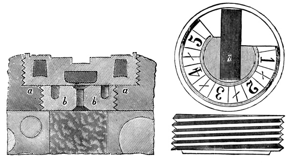
Bormann Fuse.
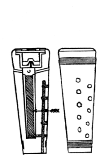
Boxer Time-Fuse.
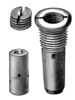
Schenkl Percussion Fuse.
The Boxer fuse is a wooden-cased fuse similar to its English original.
There is but one type of percussion fuse used in the service. It consists of a brass case containing a small iron hollow cylinder filled with composition, and having at its head a small anvil on which an ordinary percussion-cap is fitted. This cylinder is suspended midway of the case by a small brass screw through the wall of the case. The top of the fuse is closed by a small screw-cap, one side of which is hollowed in a small cavity. Ordinarily this cap is screwed in place with the cavity turned downward, so that in case the cylinder breaks from its fastening the cap cannot be struck as it enters the cavity, while the shoulders bring it up before striking. To prepare it for firing, the cap is unscrewed and reversed, putting its flat side down. When the time-fuse is used in rifled shells, the safety-plug is removed before inserting the fuse.
PRIMERS.
Both percussion and friction primers are used. The percussion primer consists of a quill tube, the upper end of which is split and spread out to form a wafer. The body is filled with fine powder, the lower end being sealed with shellac, and the wafer is filled with detonating composition, covered and sealed with shellac.
The friction primer is a quill tube filled with fine powder, and having in its head a wire igniter in contact with detonating composition. The end of the wire is twisted into a loop for the purpose of hooking a firing laniard. A small preventer-loop is attached to the primer, hooking over a small pin just forward of the vent.
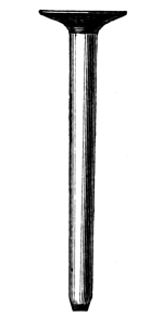
Percussion Primer.
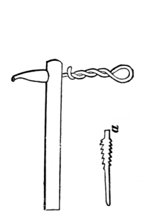
Friction Primer.
LOCKS.
Percussion-locks are used with all smooth-bores. They are of the ordinary type of heavy brass gun-locks, the pivot-hole being slotted so that in firing, after the lock strikes the primer it is drawn clear of the vent.
SIGHTS.
The smooth-bore broadside-guns are provided with centre-breech and reinforce sights, pivot-guns with centre and tangent sights, and the rifled guns with tangent-sights. The smooth-bore breech-sights are rectangular bars shipped with an angle to the rear so that two sides may be seen. These sights are marked on one side for ordinary and on the other for heavy charges, corresponding to shot and shell. The reinforce sights are of the ordinary pattern. The Parrott tangent-sight does not slide in a sight-box, but has a stem which seats in a casing. It is cylindrical, and the sight-notch, fixed to a ring, slides up and down the sight-bar. The sight-notch itself is a small capstan-head having four radial notches, and working on a screw perpendicularly to the sight-bar to allow for drift. The tangent-sight for the 8-inch M. L. R. is set at a permanent angle of deflection of 1° 50´, and is provided with a sliding leaf. The graduation on all sights except the Parrott rifles and the boat-guns is in hundreds of yards. In the remainder it is in fractions of degrees.
MACHINE-GUNS.
The Hotchkiss Revolving Cannon.
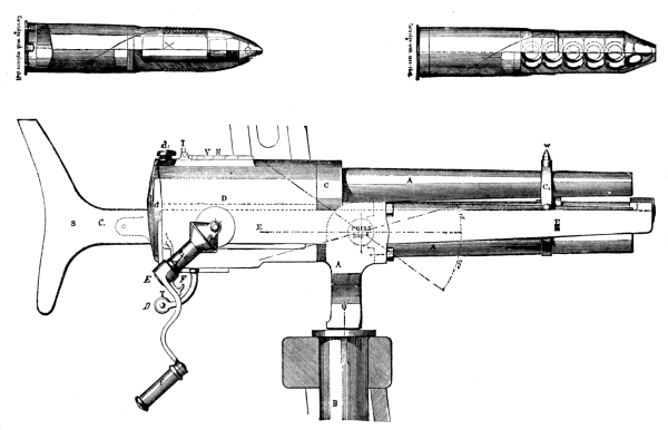
The Hotchkiss Revolving Cannon.
This gun is introduced into naval services with the especial objects of, first, repelling torpedo and boarding attacks; second, for use against light merchant vessels where a light, long-range artillery fire is most effective. The gun has five barrels, and can be fired at a rate of from 60 to 80 shots per minute without forcing. Its ammunition is shell and case-shot, the weight of projectile ranging from one and a half pounds in the light calibre to four pounds in the heavy one. The extreme range is about 4500 yards. The barrels are assembled about and revolve around a central axis, the cartridges being fed through a chamber in the left upper side of the breech-casing. There is but one lock, and each barrel fires once during a revolution. The cartridge on falling into the chamber is carried forward by a cam into its barrel, being pushed close home and receiving good support when passing in front of the firing-pin. The latter is retracted by a cam, plunging forward as the centre of each cartridge comes in front of it. The rim of the cartridge-case is then seized by an independent extractor, withdrawn, and dropped to the ground. Although the crank is turned steadily, there is a certain amount of lost motion in the revolution of the barrels. This takes place as the cartridge reaches the firing-point, and during this short time of rest one cartridge is fired and another empty case is ejected. No elevating-screw is used with this gun. It is mounted on trunnions in a saddle, and projecting from the rear of the breech-case is a wooden shoulder-piece, while underneath is a handle to allow a support with the left hand. The cartridges are permanently attached to the rear of the projectiles. The shells are of steel with a percussion fuse. The barrels of the gun are made of Whitworth compressed steel of the finest quality. This gun has up to the present time proved the most effective torpedo-gun in existence. Its only rival at present is the Nordenfeldt gun, which is not yet thoroughly developed.