Part 6 — APPENDIX
Reading edition
I. NAMES OF THE PARTS OF RIFLES—SHORT M.L.E., MARK III, AND CHARGER-LOADING M.L.E.
(a) Short M.L.E. Mark III (Figs. 59 and 60).
1. Blade foresight.
2. Foresight block.
3. Band foresight block.
4. Key foresight block.
5. Crosspin foresight block.
5A. Backsight bed.
6. Backsight bed crosspin.
6A. Backsight bed sight spring screw.
7. Backsight leaf.
8. Backsight slide.
9. Backsight slide-catch.
10. Backsight fine adjustment worm wheel.
10A. Windgauge.
10B. Windgauge screw.
11. Backsight ramps.
12. Seating for safety-catch.
13. Safety-catch.
14. Locking-bolt stem.
15. Bolt.
16. Bolt-head.
17. Striker.
18. Cocking-piece.
19. Striker collar with stud.
20. Bolt-head tenon.
21. Cocking-piece locking recesses.
22. Locking bolt.
23. Locking bolt flat.
24. Locking bolt thumb-piece.
25. Locking bolt aperture sight stem.
26. Locking bolt stop-pin recesses.
27. Locking bolt safety-catch stem.
28. Locking bolt safety-catch arm.
29. Locking bolt screw threads.
30. Locking bolt seating.
31. Bolt cam grooves.
32. Sear.
33. Sear seating.
34. Searspring.
35. Magazine catch.
36. Full bent of cocking-piece.
37. Short arm of sear.
38. Trigger ribs.
39.
40. Trigger.
41. Trigger axis pin.
41A. Magazine case.
41B. Magazine platform spring.
41C. Magazine auxiliary spring.
42. Guard-trigger.
43. Stock fore-end.
44. Spring and stud fore-end.
45. Protector backsight.
46. Handguard front and rear.
47. Spring handguard gear.
48. Lower band groove.
49. Lower band.
50. Nosecap.
51. Protector foresight.
52. Sword bar.
53. Boss for ring of sword-bayonet cross-piece.
54. Swivel seating.
55. Swivel piling.
56. Nosecap barrel opening.
57. Inner band.
58. Inner band screw.
59. Inner band screw spring.
60. Butt sling swivel.
61. Sword bayonet, pattern ’07.
62. Bridge-charger guide.
63. Cut-off.
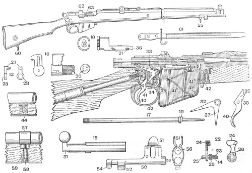
Fig. 59.—Short Rifle, Magazine Lee-Enfield (Mark III).
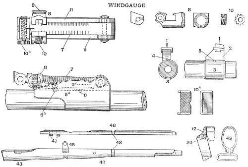
Fig. 60.—Short Rifle, Magazine Lee-Enfield (Mark III).]
(b) Charger-Loading M.L.E. (Figs. 61, 62, and 63)
1. Backsight bed
2. Backsight bed ramp.
3. Aperture sight.
4. Dial sight plate.
5. Dial sight pointer.
6. Aperture sight peep-hole.
7. Aperture sight pivot-screw.
8. Aperture sight spring.
9. Aperture sight spring ribs.
10. Aperture sight cross-cut notches.
11. Pivot aperture sight pointer.
12. Pivot screw.
13. Spring disc.
14. Bead pointer.
15. Screwed boss, fixing dial-sight.
16. Centring-pin dial-sight.
17. Index-point of pointer.
18. Bolt rib.
19. Extractor seating.
20. Bolt lug.
21. Tongue of cocking-piece.
22. Recess for lug of bolt.
23. Body bead.
24. Retaining catch.
25. Resistance shoulder.
26. Cut-off slot.
27. Body socket.
28. Body socket boss.
29. Stock-bolt.
30. Gas escape hole.
31. Bolt-breech.
32. Lever bolt-breech.
33. Lug seating.
34. Long cam groove.
35. Short cam groove.
36. Cam-shaped face.
37. Cam grooves separating studs.
38.
39. Bolt-head.
40. Bolt-head tenon.
41. Bolt-head projection.
42. Extractor slot.
43. Extractor.
44. Extractor axis-screw.
45. Extractor spring.
46. Extractor spring pin.
47. Extractor spring pin-hole.
48. Bolthead hook.
49. Striker.
50. Cocking-piece.
51. Striker collar.
51A. Cocking-piece full bent.
52. Cocking-piece half bent.
54. Cocking-piece seating for safety-catch.
55. Safety-catch.
56. Striker keeper-screw.
57. Recess in striker for the keeper-screw.
58. Safety catch stem.
59. Safety catch finger-piece.
60. Safety catch locking grooves.
61. Safety catch plunger.
62. Seating for plunger and spiral spring of safety-catch.
63. Nipple holes for plunger of safety-catch.
64. Retaining catch spring.
65. Ejector.
66. Sear.
67. Sear screw.
68. Sear seating in body.
69. Sear spring.
70. Trigger.
71. Trigger axis pin.
72. Magazine box or case.
73. Magazine platform guides.
74.
75. Magazine stop clip.
76. Magazine stop-clip stud.
77. Magazine platform.
78. Magazine clip stop.
79. Magazine tooth.
80. Magazine catch tooth.
81. Magazine catch.
82. Magazine catch finger-piece.
83. Magazine platform plate.
84. Magazine platform plate tongues.
85. Magazine platform spring.
86. Magazine platform auxiliary spring.
87. Cut-off.
88. Cut-off screw.
89. Cut-off thumb-piece.
90. Cut-off catch.
91. Guard-trigger.
92. Screw-guard front.
93. Screw-guard collar.
94. Screw-guard rear.
95. Lower band.
96. Sling swivel.
97. Nose-cap.
98. Nose-cap band.
99. Nose-cap fixing screw.
100. Piling swivel.
101. Diagonal slot in nose-cap to clear the foresight block when assembling, etc.
102. Stock-bolt, plate-keeper.
103. Stock-butt swivel.
104. Oil-bottle, Mark III (latest Mark IV).
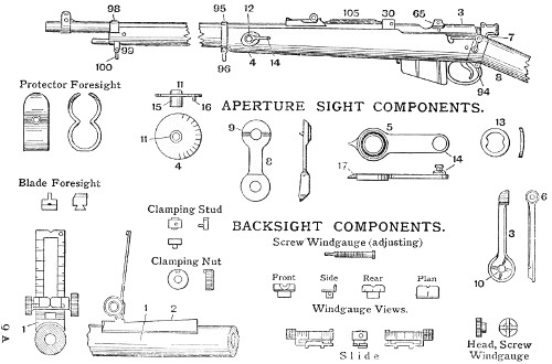
Fig. 61.—Charger-loading Lee-Enfield.
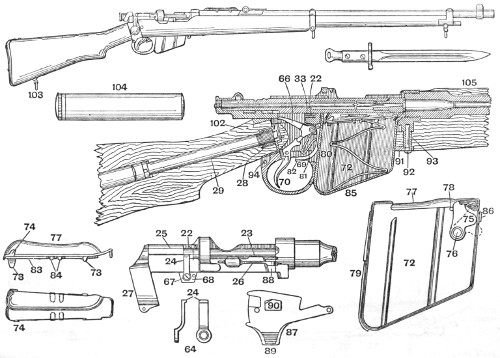
Fig. 62.—Charger-loading Lee-Enfield.
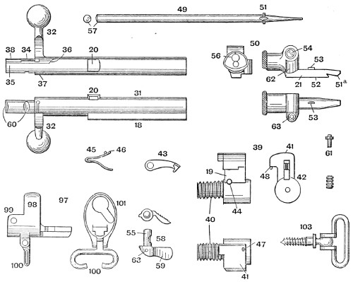
Fig. 63.—Charger-loading Lee-Enfield.
II. DIRECTIONS FOR USE OF THE LEGRET AIM TEACHER.
The Legret Aim Teacher.
This instrument provides a most easy means of teaching the elementary principles of aiming with Military Sights and also enables an instructor to check his pupils faults. Aims Chart For use with “Aim Teacher” Mark 1.
No. 1. Stage I. Proper relation of fore-sight to aiming mark. Aim taken at 6 o.c. point with fore-sight only.

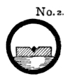
No. 2. Stage II. Proper relation of fore-sight and back-sight. Lay on sheet of paper or, sky (just above horizon most convenient).
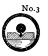
No. 3. Stage III. Proper relation between fore-sight, back-sight, and aiming mark.
No. 4. Stage IV. Instructor will first lay correct aim as in diagram 3. Rifle is then moved and shutter turned gently to left. Recruit then relays rifle as in diagram 4. Instructor turns shutter gently to right and checks faults. Care must be taken not to move “jointed arm” in this stage.
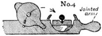
Fig. 64.—Diagrams illustrating Use of Legret Aim Teacher.
III. DIRECTIONS FOR USE OF THE AIM-CORRECTOR.
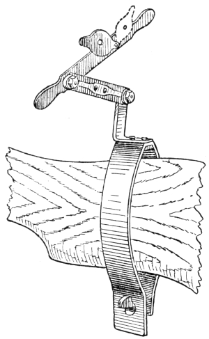
1. This device is illustrated in Fig. 65. It consists of a small steel box moving freely on a stem, so as to enable it to be made level with the back-sight when the latter is set at various elevations. It is secured to the rifle, behind the back-sight, by a spring clip. A piece of smoked glass is inserted into one of the two cross grooves, so that it forms an angle of 45 degrees with the barrel.
2. In placing the aim-corrector on the rifle, the open side of the box may be turned to the right or left, care being taken that, when the glass is inserted in the box, it is placed in the cross-groove, which will cause it to present to the observer, who is opposite the open end, a reflection of the backsight, the foresight, and the mark at which aim is to be taken. If the glass is placed in the wrong cross-groove, the only image reflected upon it will be the recruit’s eye.
3. The instructor, who may take up his position on either side of the recruit, can see the alignment of the sights while the trigger is being pressed by means of the reflection in the glass, without in any degree obscuring the recruit’s aim. He can see if aim is correctly maintained when the trigger is pressed, or if it is deflected by this act, and can tell whether the recruit has noted and correctly declared any deflection due to faulty trigger-pressing. In certain lights, the image on the glass may be rather indistinct, but with care it is possible to discern it sufficiently clearly for instruction. In correcting errors, the instructor must remember that, when looking in the glass, the reflection, as in the case of an ordinary mirror, is reversed laterally, but is correct vertically. For instance, if the sight appears upon the glass to the right of the mark, it is actually to the left of it. If, however, it appears high or low in relation to the mark, it is actually above or below the mark.
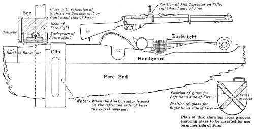
Fig. 65.—Diagram illustrating Use of Aim-Corrector.
IV. DIRECTIONS FOR USE OF THE AIMING-DISC.
The aiming-disc is a small rod, bearing a disc of metal or cardboard, painted white, about 1½ inches in diameter (Fig. 66). On the front is a black bull’s-eye ½ inch in diameter, in the centre of which is pierced a hole just large enough to admit the point of a pencil. On the back is a bull’s-eye, also ½ inch in diameter, placed so that the six o’clock line is just above the hole which is in the centre of the bull’s-eye on the front.
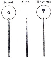
Fig. 66.—Aiming-Disc.
The instructor may ascertain the accuracy of the recruit’s aim and his power to press the trigger without disturbing aim by the use of the aiming-disc in the following manner: He should take up his position in front of the recruit at a distance of about 4 or 5 feet from the muzzle of his rifle when held to the shoulder for firing in the lying position, with his eye to the hole in front of the disc (Fig. 19). The recruit is then instructed to bring the rifle to his shoulder for aiming, to aim and press the trigger at the aiming-mark at the back of the disc.
Through the aperture at the bottom of the bull’s-eye at which the recruit takes aim and snaps, the instructor is able to see the recruit’s faults of aim, and to note whether his aim is disturbed when the trigger is pressed. The instructor is also enabled to note the rapidity with which he takes aim and presses the trigger.—This practice is useful to develop in men the power of aiming rapidly and correctly, which is essential for snapshooting and rapid firing, without the danger of their contracting bad or careless habits through hurried movements.
V. “HARMONIZING” RIFLES FOR MINIATURE RANGE PRACTICES.
1. Rifles are said to be harmonized when their slight individual differences in shooting are corrected by adjustment of sights. This harmonizing or correction of differences in the shooting of the rifles used in miniature range practices is necessary to obtain satisfactory results. Rifles must be harmonized for firing direct at targets as well as for firing with elevation, as in landscape practices. With reference to direct firing at targets, it has been found that with service rifles an elevation of 300 yards is necessary to obtain the greatest possible accuracy. Consequently, rifles must be sighted for 300 yards before being harmonized for firing direct at targets according to the method described in the following paragraph, aim being taken at the aiming-marks on the lower horizontal line, and differences being discovered by the grouping of shots on the aiming-marks—not on the line above. The sighting necessary to correct differences in each rifle will also be recorded on a board hung for reference on the miniature range, as described in para. 3.
2. Method of Harmonizing Rifles (see sky screen, Fig. 58).—(i) The following is the method of harmonizing rifles: The rifles selected for miniature range practices must be numbered from 1 on consecutively. Each rifle must be marked with its number. When this is done, a horizontal line must be drawn along the bottom of the blank sky screen. At intervals of about 12 inches along this horizontal line a number of aiming-marks must be painted. The number of aiming-marks must equal that of the rifles to be harmonized, so that there is one aiming-mark for each rifle. At a distance of 26½ inches above the line of aiming-marks another horizontal line must be drawn on the sky screen, which must be visible from the firing-point. This distance has been chosen because it is sufficient to cause shots aimed at objectives at the bottom of the landscape to clear the top of it and strike the sky screen.
(ii) Harmonizing Rifles for Elevation.—Each rifle will then be adjusted for 1,200 yards. Each rifle, thus sighted, will be fired by a reliable shot with regular aim at one of the aiming-marks. The sights of each rifle will be adjusted until shots which strike above or below the upper horizontal line on the sky screen (when it is sighted for 1,200 yards) strike the line itself. When shots fired from all the rifles strike the line after sights have been adjusted in this manner, they are said to be harmonized.
3. Record of Sighting.—The variations of each rifle, if any, from the original sighting at 1,200 yards—or 300 yards in the case of sighting for direct hits—will be noted, and its variations written down for reference against the number of the rifle on a board to be hung on the wall of the miniature range. The following is an example of the record of sighting:
Twenty-Five Yards Miniature Range.
Rifle. Elevation for Direct Hits. Elevation for Landscape Targets.
1 300 1,200
2 300 1,200
3 350 1,250
4 250 1,150
VI. SCORING AND SIGNALLING.
1. When a shot strikes the target so that the circumference of the mark cuts the outer edge of any ring or figure, it is to be counted as hitting within that ring or figure, as the case may be. No shot is to be counted unless the whole or part of the mark of the bullet is seen on the face of the target. A ricochet usually makes a long, ragged hole or mark.
2. Elementary and Figure Targets.—For scoring in Practice 22, Table B, see Note 2 below.
Signal. Methods of Signalling. Value of Hit.
Bull’s-eye or figure. Polished metal or white disc placed on shot-hole. 4 points.
Inner (remainder of inner circle). Black disc waved twice across the face of the target and placed on the shot-hole. 3 points.
Outer (remainder of elementary target) or magpie (remainder of large circle on figure target). Polished metal or white disc revolved in front of the target and then placed on the shot-hole. 2 points.
Outer (remainder of figure target). Black disc moved vertically up and down the left of the target and then placed on the shot-hole. 1 point.
Ricochet or miss Red and white flag shown on the same side as the direction of the miss. If the direction cannot be determined the flag will be waved across the face of the target. Nil.
Note 1.—The scoring bull’s-eye on second-class elementary targets is a 12-inch invisible ring.
Note 2.—In Practice 22, Table B, a hit on the figure or remainder of inner circle will count 3 points and will be signalled as a bull’s-eye. Hits elsewhere on the target will count as in table above.
Note 3.—When for any reason it is found to be impracticable to send the firers into the gallery after a grouping practice, the following signals may be used:
Bull’s-eye signal denotes a 4 -inch group.
Inner ” ” 8 ” ”
Magpie ” ” 12 ” ”
Outer ” ” 12 ” ” with one wide shot.
When the signal has been made, after a short pause, the point of the pole will be placed on the point of mean impact of the group.
3.—Figures No. 3 and No. 6 (Open Range).
Signal. Methods of Signalling. Value of Hit.
Hit The figure will be raised above the marker’s gallery and twirled. 3 points.
Ricochet or miss — Nil.
4. Figures (Miniature Range).—Scores for hits and misses as in para. 3 above.
5. Scoring in Landscape Target Practices.—(i) A measuring-rod, 26½ inches long, is required to test the accuracy of both concentrated and distributed collective grouping. The following is the method of valuing groups for scoring. When collective fire has been concentrated on any objective on the landscape, the rod is held vertically against the screen with the bottom of it resting on the point of aim. A mark is then made on the sky-screen at the top of the rod. This mark indicates where the centre of the group of shot-holes should be. For instructional practices the groups may be valued on the principle that the smaller the group the greater the fire effect. For competitions two concentric wire rectangles, 5 inches by 4 inches and 2½ inches by 2 inches respectively, may be used for scoring. The rectangles will be placed over the group, their longest sides being vertical, with their centre placed on the mark indicating where the centre of the shot group should be. Every shot in the inner rectangle will then count two points, and every shot in the remainder of the larger rectangle will count one point. For every shot outside the larger rectangle two points will be deducted.
(ii) When fire has been distributed between two points on the landscape, a mark is made 26½ inches vertically above each point, as already described. These two marks are joined by a line parallel to that along which fire has been distributed. A line 1½ inches above, and another 1½ inches below, this line are drawn parallel to it. The ends of these lines are then joined by vertical lines which pass through the two marks joined by the centre line. The rectangle formed in this manner is divided vertically into equal parts, being either one for each firer or one for each fire-unit. Each group of shots fired by a firer or a fire-unit should be found grouped in the proper part of the rectangle. Each shot in its proper part will count two points. For each shot outside its proper part two points will be deducted. For every part of the rectangle which is empty five points will be deducted.
VII. SOLANO TARGET—MARKS I AND II.
1. Official Handbook.—Full directions regarding the Solano Target and landscape targets, together with information as to their use for instruction, are contained in the official handbook—Standard Equipment for Miniature Ranges (40, War Office, 2005)—from which the following short extracts are made. One of these handbooks is supplied to units with each Solano Target, and should be kept for reference.
2. Framework and Mechanism. (Fig. 53).—The Mark I Target consists of a framework containing two tiers 10 feet long—Tier A (higher), and Tier B (lower). Tier A is fitted with crossing target mechanism, operating two target carriers from opposite ends of the Tier, and clips for disappearing targets arranged in two separate sections which can be operated simultaneously or separately. Tier B is fitted with falling target clips, which allow targets to fall when hit. Falling clips can be raised and lowered from the firing-point, like the disappearing clips on Tier A. The former can be shifted to right and left, and the latter linked together with coupling clips to facilitate any desired arrangement of targets or figures. All mechanism can be operated from the firing-point by means of cords labelled to show the particular mechanism they operate (Fig. 54).
3. Scenery.—There are two types of scenery—A and C—consisting of backgrounds which will serve to represent foreground, middle distance, and distance of almost any kind of country in any part of the world. The scenery is pasted on frames, and can be placed in position on the target in a moment (Figs. 55 and 56). Patching pieces are provided to repair shot-holes which are not visible from the firing-point to the naked eye.
4. Scenic Accessories.—The details of a landscape can be arranged on the target by placing the various scenic accessories, consisting of colour-printed representations of various natural and other features, mounted on stiff card, in any desired position on either tier by fixing them in grooves made for this purpose either behind targets or in front to represent cover. The scenic accessories are coloured and scaled for different ranges, the range being printed on each. They may be used to represent the following features:
Wooded hills. Flat-topped hills or kopjes. Conical hills. Woods. Fir-wood. Group of houses with church. Group of cottages. House. Cottage. Oak-tree. Elm-tree. Fir-tree. Palm-tree. Hedgerow. Thick hedge or bush. Bushes. Stone wall. Undergrowth. Folds of ground. Low banks. Indian hill fort. Sangar. Rocks.
5. Solano Figures.—The Solano figures are all scaled to size for various distances, and consist of the following brown, grey, or colour-printed figures. Each figure is provided with a base equal in depth to the clips which hold them in position.
Reference Number. Description. Distance (Yards).
42 Infantryman in kneeling position 200
1 Infantryman in standing position 400
2 Infantryman in prone position or firing from open trench 400
3 Infantryman firing from behind sand-bag 400
4 Infantryman firing from loophole in head cover 400
5 Infantryman in standing position 600
6 Infantryman in standing position 800
7 Infantryman in kneeling position 800
8 Infantryman in lying position 800
9 Mounted cavalryman 800
19 Machine-gun in action 800
25 Infantry line in extended order 1,000
26 Infantry line in extended order 1,200
27 Infantry line in extended order 1,400
29 Machine-gun in action 1,400
30 Infantry line in extended order 1,600
31 Infantry line in extended order 1,800
32 Company of infantry in fours 2,000
33 Infantry line in extended order 2,000
34 Field-gun in action 2,000
35 Crossing-targets Convoy waggon facing firer’s right 2,000
35a Crossing-targets Convoy waggon facing firer’s left 2,000
37 Crossing-targets Squadron of cavalry facing firer’s right 2,000
37a Crossing-targets Squadron of cavalry facing firer’s left 2,000
38 Company of infantry in fours 2,500
39 Company of infantry in column 2,800
6. Observation Practices.—Observation practices may be carried out by heaping a bank of sawdust at the foot of the apparatus below Tier B, with its surface sloping at the same angle as the end-frames. To fix targets in the sawdust, attach to Observation Practice Holders consisting of iron pins grooved at the top to hold targets. Care must be taken to remove all sawdust and grit displaced by bullets from the falling target clips and other mechanism, or their action may be clogged. A brush should be used to clean the mechanism after observation practices.
7. Landscape Targets.—The official handbook above referred to contains information as to fixing landscape targets to the framework of the Solano Target in position for instruction in firing (Fig. 57).
VIII. SOLANO ELEMENTARY AND INSTRUCTIONAL TARGETS.34
1. In Musketry Regulations, para. 361, it is laid down that in carrying out training on miniature ranges due regard must be paid to the visibility of service targets, and bull’s-eye targets must be used for the first few rounds only. In para. 206 (iii) of Musketry Regulations (see Sec. 17, para. 4 of this book) focussing the eye on the fore-sight of the rifle instead of on the object is indicated as a common fault which instructors must guard against in elementary stages of training. This error is common when bull’s-eye targets are used, and unless remedied will adversely affect shooting at service Targets, on which the eye must be focussed, and which must be watched closely when firing.
2. Elementary Targets (Figs. 67 and 68).—The Solano Elementary Targets have been designed to counteract the tendency to focus the eye on the fore-sight instead of on the target, and may be used for grouping and application practices after firing at the bull’s-eye target. These targets are coloured green, brown, and grey, instead of white, to accustom the eye to the tints of natural backgrounds against which service targets will be seen. The aiming-mark in No. 2 is less distinct than in No. 1, to accustom the eye gradually to focussing on indistinct targets when aiming.
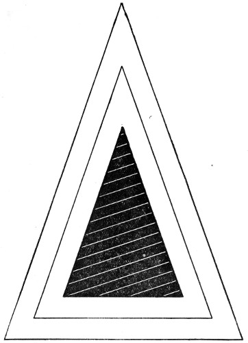
Fig. 67.—Solano Elementary Target No. 1.
(Actual size. See footnote, p. 250.)
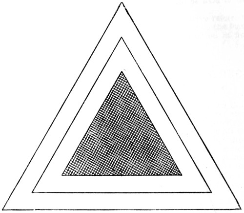
Fig. 68.—Solano Elementary Target No. 2.
(Actual size. See footnote, p. 250.)
3. Triangle Aiming and Scoring Diagrams.—(i) Triangles have been substituted in these targets for concentric circles as aiming and scoring diagrams, because they have a truer relation to the shape of the human figure in both lying and upright positions. The triangle on No. 1 target has relation to the human figure in an upright position, and the triangle on No. 2 target to the human figure in a lying position. The dimensions of the triangles on these targets correspond with the regulation grouping standards of the British Army.
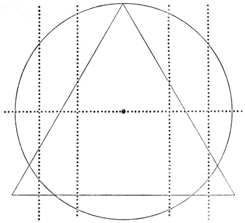
Fig. 69.—A Circle (3 Inches in Diameter) and a Triangle (3 Inches Equilateral) showing that the Triangle as Aiming and Scoring Diagram induces Closer Grouping than the Circle by Allowing Less Margin for Both Vertical and Lateral Errors represented by the Dots.
(ii) For elementary instruction in aiming the important six o’clock line—the centre of the base of the triangle—is on these targets an indicated instead of an imaginary line, as in the case of the circular bull’s-eye. More consistent grouping is induced by the triangle owing to the fact that it allows a much narrower margin for lateral errors, while its conical shape and straight base considerably curtail the scoring area for vertical errors off the six o’clock line as compared with the circle (Fig. 69). The triangle, moreover, as an aiming and scoring surface puts a premium upon a low point of aim and from the first inculcates in men, as a habit, this vital principle of marksmanship in war.
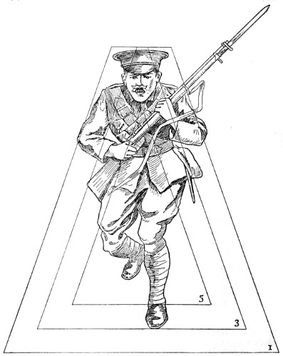
Fig. 70.—Solano Instructional Target No. 1. Upright Figure. 25 Yards = 400.
(Slightly reduced from actual size. See footnote, p. 250.)
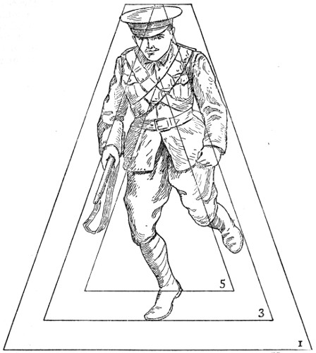
Fig. 71.—Solano Instructional Target No. 2. Upright Figure. 25 Yards = 500.
(Actual size. See footnote, p. 250.)
(iii) The centre triangles are not made smaller, firstly, because it is not desired to encourage the habit of slow aim which is engendered by individual practice at very small marks, and which militates against efficiency in snapshooting and rapid firing; and, secondly, because it is not desired to encourage men to attain a useless and disproportionate degree of excellence in firing at elementary targets which is merely preparatory for practice at service targets.
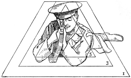
Fig. 72.—Solano Instructional Target No. 3. Lying Figure. 25 Yards = 300.
(Actual size. See footnote, p. 250.)
4. Instructional Targets (Figs. 70, 71, and 72).—(i) These targets are also coloured green, grey, and brown, the colour of the uniform of the figures on them corresponding in each case with that of the target. The figures are accurately scaled down to correct size at 25 yards for the actual distances, so as to help men in judging close range by accustoming the eye to the appearance of men seen at different distances against backgrounds which harmonize with the colour of their uniform. It must be remembered that the figures on these targets, though necessarily depicted in fixed postures as stationary marks, represent men in movement during which they are seldom stationary or seen in a fixed posture, except, possibly, for a few seconds while lying down to fire.
(ii) Accordingly, marks are not given for hits scored on any particular part of the figures depicted in fixed postures, which would usually be seen in movement, but for shots grouped in areas of comparative value as regards probable assurance of fire effect, chosen in the light of experience of war as the best aiming points for firing at figures in movement which frequently and suddenly alternate between the upright and lying positions. The centre triangles, representing the most valuable of these grouping areas, are purposely made fairly large for the reasons stated in connection with the elementary triangles—namely, that they are grouping areas for snapshooting, and not for deliberate firing.