Front matter
Reading edition
Every Boy's Mechanical Library MOTORS

Every Boy's Mechanical Library
By J. S. ZERBE, M.E.
Price, per volume, 60 cents, Net. Postage extra.
AUTOMOBILES
This is a subject in which every boy is interested. While few mechanics have the opportunity to actually build an automobile, it is the knowledge which he must acquire about every particular device used, that enables him to repair and put such machines in order. The aim of this book is to make the boy acquainted with each element, so that he may understand why it is made in that special way, and what the advantages and disadvantages are of the different types. To that end each structure is shown in detail as much as possible, and the parts separated so as to give a clear insight of the different functions, all of which are explained by original drawings specially prepared to aid the reader.
MOTORS
To the boy who wants to know the theory and the practical working of the different kinds of motors, told in language which he can understand, and illustrated with clear and explicit drawings, this volume will be appreciated. It sets forth the groundwork on which power is based, and includes steam generators, and engines, as well as wind and water motors, and thoroughly describes the Internal Combustion Engine. It has special chapters on Carbureters, Ignition, and Electrical systems used, and particularly points out the parts and fittings required with all devices needed in enginery. It explains the value of compounding, condensing, pre-heating and expansion, together with the methods used to calculate and transmit power. Numerous original illustrations.
AEROPLANES
This work is not intended to set forth the exploits of aviators nor to give a history of the Art. It is a book of instructions intended to point out the theories of flying, as given by the pioneers, the practical application of power to the various flying structures; how they are built; the different methods of controlling them; the advantages and disadvantages of the types now in use; and suggestions as to the directions in which improvements are required. It distinctly points out wherein mechanical flight differs from bird flight, and what are the relations of shape, form, size and weight. It treats of kites, gliders and model aeroplanes, and has an interesting chapter on the aeroplane and its uses in the great war. All the illustrations have been specially prepared for the work.
CUPPLES & LEON CO., Publishers, NEW YORK
Every Boy's Mechanical Library
MOTORS
BY
J. S. ZERBE, M.E.
Author of Aeroplanes—Automobiles ILLUSTRATED NEW YORK CUPPLES & LEON COMPANY
Copyright, 1915, by CUPPLES & LEON COMPANY
CONTENTS
PAGE
Introductory 1
The Subject. The Inquisitive Trait. The Reasons for Doing Things. The Mystery of Mechanism. Curiosity which prompts Investigation. The Sum of Knowledge.
Chapter I. Motors and Motive Power 5-21
The Water Fall. Water moves in One Direction only. What is Energy. Stored or Potential Energy. Kinetic Energy. Friction. Resistance. Inertia. The Law of Bodies. Internal and External Resistance. Momentum. Energy Indestructible. Wind Power. Rectilinear Motion. Oscillating Motion. Movements in Nature. How Man Utilizes the Various Movements. Kinds of Potential Energy. The Power in Heat. Energy in Steam. Energy from the Sun. Power from Water. The Turbine. Calculating Power of a Turbine. Horse Power. Foot Pounds. Power and Time. Gravitation. Utilizing the pull of Gravity. Taking Advantages of Forces. Pitting Forces Against each Other. Centripetal and Centrifugal Forces. Power not Created. Developing the Power of Motors. Experimenting.
Chapter II. The Steam Generator 22-31
Water as an absorbent of Heat. Classification of Boilers. Mode of applying Heat. The Cylindrical Boiler. The Cornish Boiler. The Water Tube Boiler. Various Boiler Types. Compound Steam Boiler. Locomotive Steam Boiler. Vertical Steam Boiler.
Chapter III. Steam Engines 32-59
The Original Turbine Engine. The Reciprocating Engine. Atmospheric Engine. The Piston. Importance of the Valve. Expanding the Steam. Balanced Valve. Rotary Valve. Engine Accessories. Efficiency of Engines. How Steam acts in a Cylinder. Indicating the Engine. Mean Efficiency. Calculating Horse Power. Condensation. Atmospheric Pressure. The Condenser. Pre-heating. Superheaters. Compounding. Triple and Quadruple Expansion Engines. The Steam Turbine. Pressure and Velocity. Form of Blades. Compounding the Jet.
Chapter IV. Fuels and Combustion 60-67
Solid Fuels. Liquid Fuels. Combustion. Oxidation. The Hydro-Carbon Gases. Oxygen and the Atmosphere. Internal Combustion. Vaporizing Fuel. Explosion by Heat Compression. How Compression Heats. Elasticity of Gases. Advantages of Compression. The Necessity of Compression.
Chapter V. The Internal Combustion Engine 68-82
Fixed Gases. Gas Engines. Energy of Carbon and Hydrogen. The Two-Cycle Type. Advantages of the Two-Cycle Engine. The Four-Cycle Engine. The Four Cycles. Ignition Point. Advantages of the Four-Cycle Type. The Loss in Power. Engine Construction. Valve Grinding. The Crank Shaft. The Cams.
Chapter VI. Carbureters 83-101
Functions of a Carbureter. Rich Mixtures. Lean Mixtures. Types of Carbureters. The Sprayer. The Surface Type. Governing a Carbureter. Primary Air. Needle Valve. Secondary Air. Requirements in a Carbureter. Size of a Carbureter. Rule for Size of Carbureters. The Throttle. Flooding. Adjustability. Surface Carbureters. Float Chamber.
Chapter VII. Ignition, Low Tension System 102-120
Electricity. Magnetism. The Armature. Characteristics of Electricity. Make and Break System. Voltage. High and Low Voltage. Low Tension method. Disadvantages of Make and Break. Amperes. Resistance. Direct Current. Alternating Current. Induction. Generating Electricity. Primary Battery. Making a Dry Cell. Energy in a cell. Wiring Methods. Series Connection. Multiple Connection. Series Multiple. Watts. Testing a Cell. Testing with Instruments. Simple Battery Make and Brake System. To Advance the Spark. The Magneto in the Circuit. Magneto Spark Plug.
Chapter VIII. Ignition, High Tension 121-140
Magnetos. Alternating Current. Cutting Lines of Force. Plurality of Loops. The Electro Magnet. The Dynamo Form. The Magneto Form. Advantages of the Magneto. Induction Coil. Changing the Current. Construction of a Coil. Primary Coil. Secondary Coil. Contact Maker. High Tension with Battery and Coil. Metallic Core for Induction Coil. The Condenser. Operations of a Vibrator Coil. The Distributor. Circuiting with Distributor.
Chapter IX. Mechanical Devices Utilized in Power 141-157
The Unit of Time. Horse Power. Proney Brake. Reversing Mechanism. Double Eccentric Reversing Gear. Balanced Slide Valve. Balanced Throttle Valve. Engine Governors. Injectors. Feed Water Heaters.
Chapter X. Valves and Valve Fittings 158-171
Check Valve. Gate Valve. Globe Valve. The Corliss Valve. Corliss Valve-operating Mechanism. Angle Valve. Rotary Valves. Rotable Engine Valves. Throttle Valves. Blow-off Valves. Pop-Safety Valves.
Chapter XI. Cams and Eccentrics 172-178
Simple Cams. Wiper Wheels. Cylindrical Cam Motion. Eccentrics. Triangularly-formed Eccentrics.
Chapter XII. Gears and Gearing 179-190
Racks and Pinions. Mangle Rack. Controlling the Pinion. Dead Center. Crank Motion Substitute. Mangle Wheels. Quick Return Motion. Accelerated Motion. Quick-return Gearing. Scroll Gearing.
Chapter XIII. Special Types of Engines 191-201
Temperatures. Artificial Heat. Zero. Liquids and Gases. Refrigeration. Rotary Engines. Caloric Engines. Adhesion Engines.
Chapter XIV. Enginery in the Development of the Human Race 202-207
Power in Transportation. Power vs. Education and the Arts. Lack of Power in the Ancient World. The Early Days of the Republic. Lack of Cohesiveness in Countries Without Power. The Railroad as a Factor in Civilization. The Wonderful Effects of Power. England as a User of Power. The Automobile. High Character of Motor Study. The Unlimited Field of Power.
Chapter XV. The Energy of the Sun, and How Heat is Measured 208-216
Fuel Economy. Direct Conversion. The Measurement of Heat. Caloric. Material Theory. Heat Transmitted in Three Ways. Conduction. Convection. Radiation.
Glossary 217
LIST OF ILLUSTRATIONS
FIG. PAGE
1. Undershot Wheel 13
2. Overshot Wheel 14
3. Primitive Boiler 24
4. Return Tubular Boiler 25
5. Cornish, or Scotch Boiler 25
6. Water Tube Boiler. End view 27
7. Water Tube Boiler. Side view 29
8. The Original Engine 33
9. Horizontal Section of Tube 33
10. Steam-Atmospheric Engine 35
11. Simple Valve Motion. First position 38
12. Simple Valve Motion. Second position 38
13. Effective pressure in a Cylinder 42
14. Indicating pressure line 44
15. Indicating the Engine 45
16. Compound Engine 53
16a. Relative Piston Pressures 54
17. Changing Pressure into Velocity 55
18. Reaction against Air 56
19. Reaction against Surface 56
20. Turbine. Straight Blades 57
21. Curved Blades 58
22. Compound Turbine 58
23. Two-Cycle Engine. First position 71
24. Two-Cycle Engine. Second position 73
25. Two-Cycle Engine. Third position 73
26. Four-Cycle Engine. First position 75
27. Four-Cycle Engine. Second position 75
28. Four-Cycle Engine. Third position 76
29. Four-Cycle Engine. Fourth position 76
30. Valve Grinding 81
31. Carbureter 87
32. Carbureter 95
33.v Surface Carbureter 98
34. Dry Cell 108
35. Series Connection 109
36. Multiple, or Parallel Connection 110
37. Series-Multiple Connection 111
38. Circuit Testing 113
39. Make and Break, with Battery 114
40. Make and Break, with Magneto 117
41. Magneto Spark Plug 119
42. Illustrating Alternating Current 122
43. Alternating Current. Second position 122
44. Alternating Current. Third position 123
45. Alternating Current. Fourth position 124
46. Making the Circuit 125
47. The Dynamo 126
48. The Magneto 126
49. Current by Induction 128
50. Induction Coil 129
51. Typical Induction Coil 130
52. Contact Maker 131
53. Typical Circuiting, Jump spark Ignition 132
54. Metallic Core, Induction Coil 133
55. Condenser 134
56. Vibrator Coil and Connections 135
57. The Distributer 137
58. Circuiting with Distributer 138
59. Illustrating the Unit of Time 142
60. The Proney Brake 143
61. Double Eccentric Reversing Gear 146
62. Reversing Gear, Neutral 146
63. Reversing Gear, Reversed 147
64. Single Eccentric Reversing Gear 147
65. Balanced Slide Valve 148
66. Valve Chest. Double Port Exhaust 149
67. Balanced Throttle-Valve 150
68. Watt's Governor 151
69. The Original Injector 152
70. Injector with movable Combining Tube 154
71. Feed Water Heater 156
72. Check Valve 158
73. Gate Valve 159
74. Globe Valve 160
75. Corliss Valve 162
76. Corliss Valve-operating Mechanism 163
77. Angle Valve 164
78. Rotary-Valve 165
79. Two-way Rotary 165
80. Rotary Type 166
81. Two-Way Rotary Type 166
82. Butterfly Throttle 167
83. Angle Throttle 167
84. Slide Throttle 168
85. Two-slide Throttle 168
86. Blow-off Valve 169
87. Safety Pop Valve 170
88. Heart Shaped 173
89. Elliptic 173
90. Double Elliptic 173
91. Single Wiper 174
92. Double Wiper 174
93. Tilting Cam 174
94. Cam Sector 175
95. Grooved Cam 175
96. Reciprocating Motion 175
97. Pivoted Follower for Cam 176
98. Eccentric 177
99. Eccentric Cam 177
100. Triangularly-formed Eccentric 178
101. Rack and Pinion 180
102. Rack Motion 180
103. Plain Mangle Rack 181
104.Mangle Rack Motion 181
105. Alternate Circular Motion 181
106. Controlling Pinion for Mangle Rack 182
107. Illustrating Crank-pin Movement 183
108. The Dead Center 184
109. Crank Motion Substitute 184
110. Mangle Wheel 185
111. Quick Return Motion 186
112. Accelerated Circular Motion 187
113. Quick Return Gearing 188
114. Scroll Gearing 189
115. Simple Rotary Engine 196
116. Double-feed Rotary Engine 198
117. Adhesion Motor 200
INTRODUCTORY
The motor is the great dominating factor in the world of industry. Every wheel and spindle; every shaft and loom, and every piece of mechanism which has motion, derives it from some sort of motor.
The term motor has a wider significance than any other word. A steam engine is a motor, and so, also, is a dynamo, a water wheel or a wind mill.
It would be just as descriptive to call a wind mill a wind motor, or a steam engine a steam motor, as to adhere to the old terms; and, on the other hand, since it would be out of place to call a dynamo or a wind mill an engine, the word motor seems best adapted to express the meaning of every type of mechanism which transforms energy into motion.
In considering the subject I shall proceed on the theory that the boy knows nothing whatsoever of the subject, nor the terms used to designate the various phases, subjects and elements. It must be elementary in its character, and wholly devoid of technical terms or sentences.
While it is necessary to give information in a book of this character, on the methods for figuring out power, it must be done without resorting to the formulas usually employed in engineering works, as they are of such a nature that the boy must have some knowledge of the higher mathematics to follow out the calculations employed.
Indeed, every phase should be brought within the mental view of the boy, and to do this may occasionally necessitate what might appear to be long drawn out explanations, all of which, it is hoped, will be the means of more clearly presenting the subject.
The opening chapters, which treat of the fundamentals, will be as nearly complete as possible, and thus lay a foundation for the work we shall be called upon to perform, when we treat of the structures of the different parts and devices in the various types of motors.
The object is to explain power in its various phases, how derived, and the manner in which advantage is taken of the elements, and substances with which we are brought into contact. The reasons for each step are plainly set forth with the view of teaching the boy what power means, rather than to instruct him how to make some particular part of the machinery.
The Inquisitive Trait.—My experience has impressed me with the universality of one trait in boys, namely, that of inquisitiveness. Put a machine before a boy and allow him to dissect it, and his curiosity will prompt him to question the motive for the particular construction of each part of its make-up.
The Reasons for Doing Things.—He is interested in knowing the reason why. Every boy has the spirit of the true investigator,—that quality which seeks to go behind or delve down deeply. This is a natural instinct.
The Mystery of Mechanism.—If this taste is gratified, and he thereby learns the mystery of the machine, what a wonderful world is opened to him! The value of the lesson will depend, in a large measure, on the things which he has found out for himself. It is that which counts, because he never forgets that which he has dug out and discovered.
Curiosity Which Prompts Investigation.—I recall a farmer's boy whose curiosity led him to investigate the binding mechanism of a reaper. It was a marvel to him, as it has been to many others. He studied it day after day, and finally, unaided mastered the art. That was something which could not be taken away from him.
It was a pleasure to hear him explain its operation to a group of boys, and men, too, in which he used the knot itself to explain how the various fingers and levers coöperated to perform their functions. It was an open book to him, but there was not one in the group of listeners who could repeat the explanation.
The Sum of Knowledge.—It is the self-taught boy who becomes the expert. The great inventors did not depend on explanations. A book of this character has a field of usefulness if it merely sets forth, as far as possible, the sum of useful knowledge which has been gained by others, so as to enable the boy to go forward from that point, and thus gain immensely in time.
There is so much that has been developed in the past, with reference to the properties of matter, or concerning the utility of movements, and facts in the realm of weights, measures, and values of elements which he must deal with, that, as he studies the mechanical problems, the book becomes a sort of cyclopedia, more than a work designed to guide him in the building of special engines or motors.
The Author.
MOTORS
CHAPTER I
MOTORS AND MOTIVE POWER
What makes the wheels turn round? This simple question is asked over and over again. To reply means pages of answers and volumes of explanations.
The Water Fall.—Go with me to the little stream I have in mind, and stand on the crest of the hill where we can see the water pouring down over the falls, and watch it whirling away over the rocks below.
The world was very, very old, before man thought of using the water of the falls, or the rushing stream below, to grind his corn or to render him other service.
Water Moves in One Direction Only.—What the original man saw was a body of water moving in one direction only. When he wanted to grind corn he put it in the hollow of a rock, and then beat it with a stone, which he raised by hand at each stroke. In doing so two motions were required in opposite directions, and it took thousands of years for him to learn that the water rushing along in one direction, could be made to move the stone, or the pestle of his primitive grinding mill, in two directions.
It took him thousands of years more to learn another thing, namely, that the water could be made to turn the stone round, or rotate it, and thus cause one stone, when turning on another, to crush and grind the grain between them.
Now, as we go along with the unfolding of the great question of motors, we must learn something of the terms which are employed, to designate the different things we shall deal with, and we ought to have some understanding of the sources of power.
What Is Energy?—The running, as well as the falling water represent energy. This is something which is in the thing, the element, or the substance itself. It does not come from without. It is not imparted to it by anything.
Stored or Potential Energy.—At the top of the falls, look at that immense rock. It has been there for centuries. It, also, has energy. There is stored within it a tremendous power. You smile! Yes, the power has been there for ages, and now by a slight push it is sent crashing down the precipice. The power developed by that fall was thousands of times greater than the push which dislodged it.
But, you say, the push against the stone represented an external force, and such being the case, why do you say that power is within the thing itself? The answer is, that not one iota of the power required to push the stone off its seat was added to the power of the stone when it fell. Furthermore, the power required to dislodge the stone came from within me, and not from any outside source.
Here we have two different forms of energy, but both represent a moving force. The power derived from them is the same.
Kinetic Energy.—The energy of the falling water or stone is called Kinetic energy. In both cases the power developed came from within themselves and not from any exterior source.
The difference between Potential and Kinetic Energy is therefore that Potential Energy represents the capacity to do work, while Kinetic Energy is the actual performance of work.
Friction.—In every form of energy there is always something to detract from it or take away a portion of its full force, called friction. When a shaft turns, it rubs against the bearings, and more or less power is absorbed.
When a wheel travels over the ground friction is ever present. The dislodging of the stone required ten pounds of energy, but a thousand pounds was developed by the fall. The water rushing along its rocky bed has friction all along its path.
Resistance.—This friction is a resistance to the movement of a body, and is ever present. It is necessary to go back and examine the reason for this. As long as the stone was poised at the top of the precipice it had latent or potential energy, which might be termed power at rest. When it fell it had power in motion. In both cases gravity acted upon the stone, and in like manner on the water pouring over the falls.
Inertia.—Inertia or momentum is inherent in all things and represents the resistance of any body or matter, to change its condition of rest or standing still into motion, and is then called Inertia of Rest, or the resistance it offers to increase or decrease its speed when moving, and is then called Inertia of Motion.
Inertia or momentum is composed by the weight of the body and its speed and is measured by multiplying its weight by its speed.
The law is, that when a body is at rest it will remain at rest eternally, and when in motion it will continue in motion forever, unless acted on by some external force or resistance. An object lying on the ground has the frictional resistance of the earth to prevent its moving. When the object is flying through space it meets the air and has also the downward pull of gravity, which seek to bring it to rest.
These resisting forces are less in water, and still less in gases, and there is, therefore, a state of mobility in them which is not found in solids.
Internal and External Resistance.—All bodies are subject to internal, as well as external resistance. The stone on the cliff resisted the movement to push it over. Weight was the resisting internal force, but when the stone was moving through the air, the friction with the air created external resistance.
Energy Indestructible.—There is another thing which should be understood, and that is the absolute indestructibility of energy. Matter may be changed in form, or in the direction of its motion, by the change of kinetic into potential energy, or vice versa, but the sum total of the energy in the world is unalterable or constant.
The tremendous power developed by the stone when it plunged through space and struck the rocks below, developed a heat at its impact. Thus the moving force which was a motion in one direction was converted into another form of energy, heat. The expansion of the material exposed to the heat also represented energy.
When powder explodes and absolutely changes the form of the substance, its volume of expansion, if it should be retained within a vessel, would perform a certain amount of work, and the energy is thus transferred from one form to another without ceasing.
Wind Power.—Primitive man also saw and felt the winds. He noted its tremendous power, but he could not see how a force moving in one direction only could be utilized by him.
Rectilinear Motion.—This movement of the wind in one direction, like the water flowing along the bed of the river, is called rectilinear motion. It required invention to convert rectilinear into circular motion.
Oscillating Motion.—When he threshed his grain and winnowed it by shaking it to and fro, to rid it of the chaff, the idea of using the wind to produce an oscillating motion did not occur to him. After circular motion was produced, the crank was formed and thus the oscillating movement was brought about.
Movements in Nature.—All movements in nature are simple ones, of which the following are illustrations:
1. Rectilinear, which, as stated, means in a straight line.
2. Circular, like the motion of the earth on its axis, once every twenty-four hours.
3. Oscillatory, like a to and fro movement, the swaying branches of trees, or the swinging of a pendulum.
How Man Utilizes the Various Movements.—What man has done is to utilize the great natural forces in nature in such a way as to produce these movements at will, in either direction, with greater or less speed, at regular or irregular intervals, and at such amplitudes as are required to perform the necessary work.
Kinds of Potential Energy.—Now, materials have within themselves potential energy of various kinds. Thus, powder, if ignited, will burn, and in burning will expand, or explode, as we term it. This is true also of oils and gases. The expansion pressure produced from such substances depends on the speed at which they will burn, and in so confining the burning substances that a great pressure is produced.
The Power in Heat.—The pressure of all such substances against the confining medium depends on heat. Any gas which has 523 degrees of heat imparted to it will expand double its volume. If one cubic inch of water is converted into steam the latter will occupy one cubic foot of space under atmospheric pressure,—that is, it will expand over 1700 times.
Energy in Steam.—If the steam thus generated is now subjected to 523 degrees of heat additional, it will occupy over 3400 cubic inches of space. It will thus be seen why steam, gas, and gasoline engines are called heat engines, or heat motors.
Energy From the Sun.—Many attempts have been made to utilize the heat of the sun, to turn machinery, but the difficulty has been to secure sufficient heat, on the one hand, and on the other to properly cool down the heated gases, so that the various liquid and solid fuels are required to make the heat transformations.
Power From Water.—In the use of water two forms are available, one where the water is moving along or falling in a constant open stream; and the other where the flowing water is confined and where its flow can be regulated and controlled. The latter is more available for two reasons:
First: Economy in the use of water.
Second: Ability to control the speed or movement of the motor.
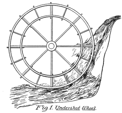
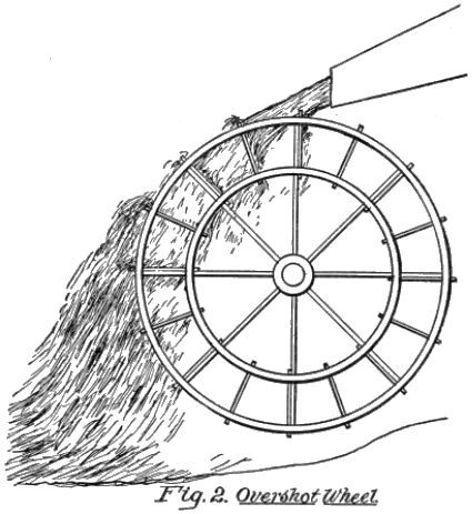
With running or falling streams a large surface is required, and the wheels turn slowly. Two well-recognized forms of wheels have been employed, one called the undershot, or breast wheel, shown in Fig. 1, and the other the overshot, illustrated in Fig. 2.
In both types it is difficult to so arrange them as to shut off the power or water pressure when required, or to regulate the speed.
The Turbine.—Wheels which depend on the controllable pressure of the water are of the turbine type. The word is derived from the Latin word turbo, meaning to whirl, like a top. This is a type of wheel mounted on the lower end of a vertical or horizontal shaft, within, or at the bottom, of a penstock. The perimeter of the wheel has blades, and the whole is enclosed within a drum, so that water from the penstock will rush through the tangentially-formed conduit into the drum, and strike the blades of the wheel.
A column of water one inch square and twenty-eight inches high weighs one pound,—or, to express it in another way, the pressure at the bottom of such a column is one pound, and it is a pound for each additional 28 inches.
If there should be a head or height of water column of seven feet, the pressure on each square inch of water at the bottom of the penstock would be three pounds to the square inch. Assuming the opening or duct leading to the wheel blades should be 12 × 12 inches, and also the blades be 12 × 12 inches, the area would be equal to 144 square inches, and this multiplied by three pounds would equal 432 pounds pressure against the blades.
Calculating Power of a Turbine Wheel.—The power of such a wheel depends principally on two things. First, the arrangement of the blades with reference to the inflowing water; and, second, the discharge port, or ability of the water to free itself from the wheel casing.
Let us assume that the diameter of the wheel at the center of the blades is two feet, which would, roughly estimating, give a circumference of six feet, or a travel of each particular blade that distance at each turn of the wheel.
If the wheel turns one hundred times a minute, and this is multiplied by the circumference of the wheel (six feet), the result is 600 feet. This, again, multiplied by 432 pounds (which represents the pressure of the water on the entire discharge opening), and we have a product of 259,200, which represents foot pounds.
This means the same work as if 259,200 pounds would have been lifted through a space of one foot in one minute of time. To ascertain how much power has been developed we must know how many foot pounds there are in a horse power.
Horse Power.—It is determined in this way: any force which is capable of raising 550 pounds one foot in one second of time, is developing one horse power. A man might have sufficient strength to raise such a weight once, twice, or a dozen times in succession, but if he should try to do it sixty times a minute he would find it a trying, if not impossible task.
Foot Pounds.—If he should be able to lift 550 pounds sixty times within a minute, he would have lifted 33,000 pounds one foot in one minute of time (550 × 60), and thus have developed one horse power.
As the water wheel, in our calculations above, raised 259,200 pounds in that period of time, this figure divided by 33,000 shows that a little more than 73/4 horse power was developed, assuming, of course, that we have not taken into account any waste, or loss by friction, or otherwise.
This method of determining one horse power should be carefully studied. Always keep in mind the main factor, 33,000 pounds, and this multiplied by one foot, the result will be 33,000 foot pounds,—that is, one horse power.
It would be just the same, however, if it were possible to raise one pound 550 times in one second, or one pound 33,000 times within a minute.
Power and Time.—You are thus brought face to face with another thing which is just as important, namely, that, in considering power, time, as well as energy, must be considered. If a man, by superior strength, could be able to raise 550 pounds once within a second, then skip a few seconds, take another hold, and again raise it that distance, he would not be developing one horse power for a minute, but only for one second while he lifted the weight. For the whole minute he would only develop a certain number of foot pounds, and less than 33,000 foot pounds.
If, within a minute, he succeeded in raising it one foot for six times, this would be six times 550, equal to 3,300 foot pounds, or just one-tenth of one horse power for one minute; so time is just as important as the amount lifted at each effort.
Gravitation.—Now, let us examine power from another standpoint. Every attempt which man makes to produce motion is an effort to overcome some resistance. In many cases this is "weight or gravity." While humanity unceasingly antagonizes the force of gravity it is constantly utilizing the laws of gravitation.
Utilizing the Pull of Gravity.—The boy laboriously drags his sled to the top of the hill against gravity, and then depends on that force to carry him down. We have learned to set up one force in nature against the other. The running stream; the moving winds; the tides; the expansive force of all materials under heat, are brought into play to counteract the great prevailing agency which seeks to hold everything down to mother earth.
Utilizing Forces.—The Bible says: Blessed is he who maketh two blades of grass grow where one grew before. To do that means the utilization of forces. Improved machinery is enabling man to make many blades grow where one grew before. New methods to force the plow through the soil; to dig it deeper; to fertilize it; and to harvest it; all require power.
Pitting Forces Against Each Other.—Man has discovered how to pit the forces of nature against each other, and the laws which regulate them.
Centripetal and Centrifugal Forces.—Gravity, that action which seeks to draw all matter toward the center of the earth, is termed centripetal force. But as the earth rotates on its axis another force is exerted which tends to throw substances outwardly, like dirt flying from the rim of a wheel. This is called centrifugal force.
Man utilizes this force in many ways, one of which is illustrated in the engine governor, where the revolving balls raise the arms on which they swing, and by that means the engine valve is regulated.
Power Not Created.—In taking up the study of this subject start with a correct understanding of the source of all power. It is inherent in all things. All we can do is to liberate it, or to put the various materials in such condition, that they will exert their forces for our uses. (See Page nine, "Energy Indestructible.")
A ton of coal, when burned, produces a certain amount of heat, which, if allowed to escape, will not turn a wheel. But if confined, it expands the air, or it may convert water into steam which will turn ponderous machinery. Niagara Falls has sent its great volume into the chasm for untold centuries, but it has never been utilized until within the last twenty years. The energy has been there, nevertheless; and so it is with every substance of which we have knowledge.
The successive steps, wherein the experimenter and the inventor have greatly improved on the original inventions, will be detailed as we go along through the different types of motors.
Developing the Power of Motors.—This development in the art is a most fascinating study. It is like the explorer, forcing his way through a primeval forest. He knows not what is beyond. Often, like the traveler, he has met serious obstructions, and has had to deviate from his course, only to learn that he took the wrong direction and had to retrace his steps.
The study of motors and motive power is one which calls for the highest engineering qualities. In this, as in every other of the mechanical arts, theory, while it has an important function, occupies second place.
Experimenting.—The great improvements have been made by building and testing; the advance has been step by step. Sometimes a most important invention will loom up as a striking example to show how a valuable feature lies hidden and undeveloped.
An illustration of this may be cited with respect to the valve of the steam engine. For four hundred years there was no striking improvement in the valve. The various types of sliding and rocking valves were modified and refined until it was assumed that they typified perfection. At one stroke the Corliss valve made such an immense improvement that the marvel was as much in its simplicity as in its performance.
The reasons and the explanations will be set forth in the section which analyzes valve motion. In this, as in other matters, it shall be our aim to explain why the different improvements were regarded as epochs in the production of motors.
CHAPTER II
THE STEAM GENERATOR
The most widely known and utilized source of power is the steam engine. Before its discovery wind and water were the only available means, except the muscular power of man, horses and other animals, which was used with the crudest sort of contrivances.
In primitive days men did not value their time, so they laboriously performed the work which machinery now does for us.
The steam engine, like everything else which man has devised, was a growth, and, singular as it may seem, the boiler, that vital part of the organism, was, really, the last to receive due consideration and improvement.
As the boiler is depended upon to produce the steam pressure, and since the pressure depends on the rapid and economical evaporation of water, the importance of the subject will be understood in treating of the steam engine.
Water as an Absorbent of Heat.—Water has the capacity to absorb a greater amount of heat than any other substance. A pewter pot, which melts at 500 degrees, will resist 2000 degrees of heat if it is filled with water, since the latter absorbs the heat so rapidly that the temperature of the metal is kept near the boiling point of water, which is 212 degrees.
Notwithstanding the great heat-absorbing qualities of water, a large portion of the heat of the fuel passes through the flues and escapes from the stack. This fact has caused inventors to devise various forms of boilers, the object being to present as large an area of water as possible to the heat of the burning fuel. How that was accomplished we shall try to make plain.
Classification of Boilers.—Numerous types of boilers have been devised, the object being, in all cases to evaporate the largest amount of water with the minimum quantity of fuel. All boilers may be put under two general heads, namely, those which contain a large quantity of water, and those which are intended to carry only a small charge.
In the first division the boilers are designed to carry a comparatively small pressure, and in the latter high pressures are available.
Mode of Applying Heat.—The most important thing to fully understand is the manner in which heat is applied to the boiler, and the different types which have been adapted to meet this requirement.
The Cylindrical Boiler.—The most primitive type of boiler is a plain cylindrical shell A, shown in Fig. 3, in which the furnace B is placed below, so that the surface of the water in contact with the fire area is exceedingly limited.
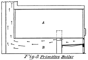
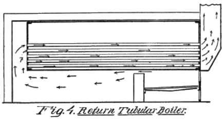
In such a type of boiler it would be impossible for water to extract more than quarter the heat of the fuel. Usually it was much less. The next step was to make what is called a return tubular type in which the heat of the burning gases is conveyed to the rear end of the boiler, and then returned to the front end through tubes.
Fig. 4 shows this construction. The head of the shell holds the ends of a plurality of tubes, and the products of combustion pass through the conduit, below the boiler to the rear end, and are conducted upwardly to the tubes. As all the tubes are surrounded by water, it will absorb a large amount of the heat as the gases move through, and before passing out of the stack.
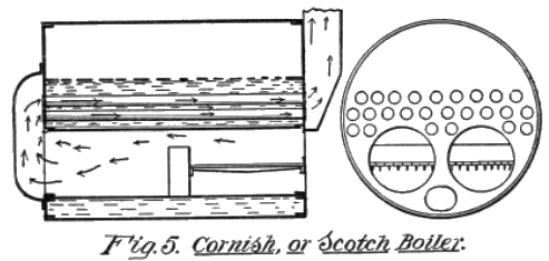
The Cornish Boiler.—One of the most important inventions in the generation of steam was the Cornish boiler, which for many years was the recognized type for marine purposes. It had the advantage that a large amount of water could be carried and be subjected to heat at all times. Aside from that it sought to avoid the great loss due to radiation.
It will be seen from an examination of Fig. 5 that the shell is made very large, and its length does not exceed its diametrical measurement. Two, and sometimes three, fire tubes are placed within the shell, these tubes being secured to the heads. Surrounding these fire tubes, are numerous small tubes, through which the products of combustion pass after leaving the rear ends of the fire tubes.
In these boilers the tubes are the combustion chambers, and are provided with a grating for receiving the coal, and the rear ends of the tubes are provided with bridge walls, to arrest, in a measure, the free exit of the heated gases.
These boilers would be very efficient, if they could be made of sufficient length to permit the water to absorb the heat of the fuel, but it will be seen that it would be difficult to make them of very great length. If made too small diametrically the diameter of the fire boxes would be reduced to such an extent that there would not be sufficient grate surface.
It is obvious, however, that this form of boiler adds greatly to the area of the water surface contact, and in that particular is a great improvement.
The Water Tube Boiler.—In the early days of the development of boilers, the universal practice was to have the products of combustion pass through the flues or the tubes. But quick generation of steam, and high pressures, necessitated a new type. This was accomplished by connecting an upper, or steam drum, with a lower, or water drum, by a plurality of small tubes, and causing the burning fuel to surround these tubes, so that the water, in passing upwardly, would thus be subjected to the action of the fuel.
This form of boiler had two distinct advantages. First, an immense surface of water could be provided for; and, second, the water and steam drums could be made very small, diametrically, and thus permit of very high pressures.
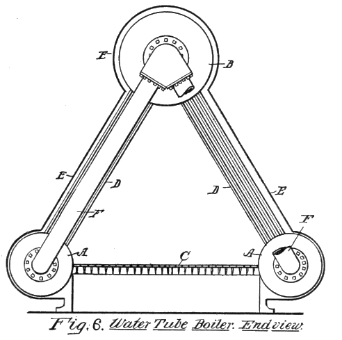
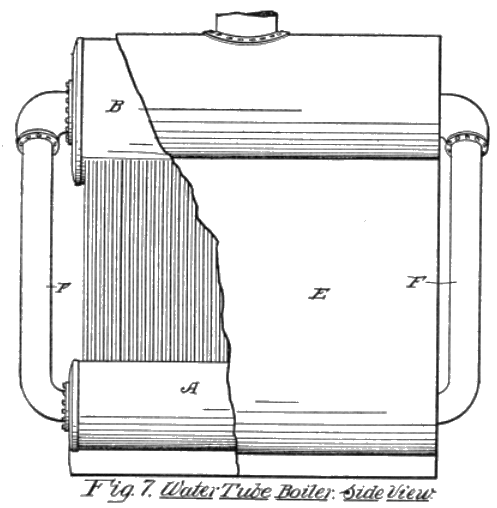
In Fig. 6, which is designed to show a well known type of this structure, A A, represent the water drums and B, the steam drum. The water drums are separated from each other, so as to provide for the grate bars C, and each water drum is connected with the steam drum by a plurality of tubes D.
It will thus be seen that a fire box, or combustion chamber, is formed between the two sets of tubes D, and to retain the heat, or confine it as closely as possible to the tubes, a jacket E is placed around the entire structure.
The ends of the water and steam drums are connected by means of tubes F, shown in side view, Fig. 7, for the return or downward flow of the water. The diagrams are made as simple as possible, to show the principal features only. The structure illustrated has been modified in many ways, principally in simplifying the construction, and in providing means whereby the products of combustion may be brought into more intimate contact with the water during its passage through the structure.
As heretofore stated, this type of boiler is designed to carry only a small quantity of water, so that it is necessary to have practically a constant inflow of feed water, and to economize in this respect the exhaust of the steam engine is used to initially heat up the water, and thus, in a measure, start the water well on its way to the evaporation point before it reaches the boiler.
Various Boiler Types.—The different uses have brought forth many kinds of boilers, in order to adapt them for some particular need. It would be needless to illustrate them, but to show the diversity of structures, we may refer to some of them by their characteristics.
Compound Steam-Boiler.—This is a battery of boilers having their steam and water spaces connected, and acting together to supply steam to a heating apparatus or a steam engine. These are also made by combining two or more boilers and using them as a feed water heater or a superheater, for facilitating the production of steam, or to be used for superheating steam.
The terms feed water heater and super heater are explained in chapter III.
Locomotive Steam-Boiler.—This is a tubular boiler which has a contained furnace and ash pit, and in which the gases of combustion pass from the furnace directly into the horizontal interior tubes, and after passing through the tubes are conveyed directly into the smoke box at the opposite ends of the tubes. The name is derived from the use of such boilers on locomotive engines, but it is typical in its application to all boilers having the construction described, and used for generating steam.
Vertical Steam-Boiler.—This is a form of construction in which the shell, or both the shell and the tubes, are vertical, and the tubes themselves may be used to convey the products of combustion, or serve as the means for conveying water through them, as in the well known water tube type.
This form of boiler is frequently used to good advantage where it is desired to utilize ground space, and where there is sufficient head room. Properly constructed, it is economical as a steam generator.
From the foregoing it will be seen that the structural features of all boilers are so arranged as to provide for the exposure of the largest possible area of water to a heated surface so that the greatest amount of heat from the fuel may be absorbed.
CHAPTER III
STEAM ENGINES
The first steam engine was an exceedingly simple affair. It had neither eccentric, cylinder, crank, nor valves, and it did not depend upon the pressure of the steam acting against a piston to drive it back and forth, because it had no piston.
It is one of the remarkable things in the history and development of mechanism, that in this day of perfected steam engines, the inventors of our time should go back and utilize the principles employed in the first recorded steam engine, namely, the turbine. Instead of pressure exerting a force against a piston, as in the reciprocating engine, the steam acted by impacting against a moving surface, and by obtaining more or less reaction from air-resistance against a freely discharging steam jet or jets.
The original engine, so far as we have any knowledge, had but one moving part, namely, a vertical tubular stem, to which was attached a cross or a horizontal tube.
The Original Engine.—Figure 8 is a side view of the original engine. The vertical stem A is pivoted to a frame B, and has a bore C which leads up to a cross tube D. The ends of the tube D are bent in opposite directions, as shown in the horizontal section, Fig. 9.
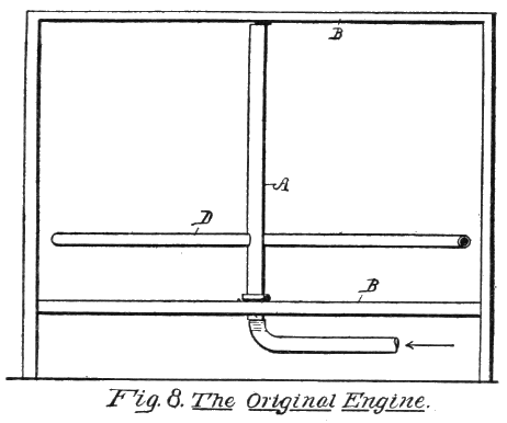
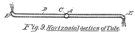
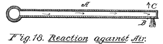
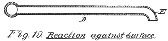
Steam enters the vertical stem by means of a pipe, and as it rushes up and out through the lateral tubes D, it strikes the angles E at the discharge ends, so that an impulse is given which drives the ends of the tube in opposite directions. As the fluid emerges from the ends of the tubes, it expands, and on contacting with the air, the latter, to a certain extent, resists the expansion, and this reacts on the tube. Thus, both forces, namely, impact and reaction, serve to give a turning motion to the turbine.
The Reciprocating Engine.—The invention of this type of engine is wrapped in mystery. It has been attributed to several. The English maintain that it was the invention of the Marquis of Worcester, who published an account of such an engine about 1650. The French claim is that Papin discovered and applied the principle before the year 1680.
In fact, the first actual working steam engine was invented and constructed by an Englishman, Captain Savery, who obtained a patent for it in 1698. This engine was so constructed as to raise water by the expansion and condensation of steam, and most engines of early times were devoted solely to the task of raising water, or were employed in mines.
Atmospheric Engines.—When we examine them it is difficult to see how we can designate them as steam engines. The steam did not do the actual work, but a vacuum was depended on for the energy developed by the atmospheric pressure.
A diagram is given, Fig. 10, showing how engines of this character were made and operated. A working beam A was mounted on a standard B, and one end had a chain C on which was placed heavy weights D. Near this end was also attached the upper end of a rod E, which extended down to a pump.
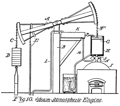
The other end of the working beam had a chain F, which supported a piston G working within a vertically-disposed cylinder H. This cylinder was located directly above a boiler I, and a pipe J, with a valve therein, was designed to supply steam to the lower end of the cylinder.
A water tank K was also mounted at a point above the cylinder, and this was supplied with water from the pump through a pipe L. Another pipe M from the tank conducted water from the tank to the bottom of the cylinder.
The operation of the mechanism was as follows: The steam cock N, in the short pipe J, was opened to admit steam to the cylinder, below the piston. The stem of the steam cock also turned the cock in the water pipe M, so that during the time the steam was admitted the water was shut off.
When the steam was admitted so that it filled the space below the piston, the cock N was turned to shut off the steam, and in shutting off the steam, water was also admitted. The injection of water at once condensed the steam within the cylinder so a partial vacuum was formed.
It will be remembered that as steam expanded 1700 times, the condensation back into water made a very rarified area within the cylinder, and the result was that the piston was drawn down, thus raising both the weight D and also the pump rod E. This operation was repeated over and over, so long as the cock N was turned.
The turning of the stem of this cock was performed manually,—that is, it had to be done by hand, and boys were usually employed for doing this. When, later on, some bright genius discovered that the valve could be turned by the machinery itself, it was regarded as a most wonderful advance.
The discovery of this useful function has been attributed to Watt. Of this there is no conclusive proof. The great addition and improvements made by Watt, and which so greatly simplified and perfected the engine, were through the addition of a separate condenser and air pump, and on these improvements his fame rests.
From the foregoing it will be seen that the weight D caused the piston to travel upwardly, and not the force of the steam, and the suction produced by the vacuum within the cylinder did the work of actuating the pump piston, so that it drew up the water.
The Piston.—From this crude attempt to use steam came the next step, in which the steam was actually used to move the piston back and forth and thus actually do the work. In doing so the ponderous walking beam was dispensed with, and while, for a long period the pistons were vertically-placed, in time a single cylinder was used, and a crank employed to convert the reciprocating into a circular motion.
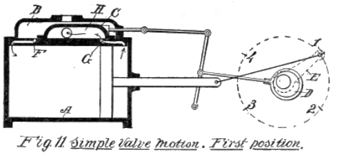
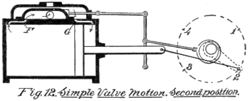
Fig. 11 shows a simple diagram of a steam engine, so arranged that the operation of the valves may be readily understood. The cylinder A has a steam chest B, which contains therein a slide valve C to cover the ports at the ends of the cylinder. This figure shows the crank turning to the right, and the eccentric D on the engine shaft is so placed, that while the crank E is turning past the dead center, from 1 to 2, the slide valve C is moved to the position shown in Fig. 12, thereby covering port F and opening port G.
It will be seen that the slide valve is hollowed within, as at H, and that the exhaust port I leads from this hollowed portion while the live steam from the boiler enters through pipe J and fills the space K of the chest.
In Fig. 11 live steam has been entering port F, thus driving the piston to the right. At the same time the exhaust steam at the right side of the piston is discharging through the port G and entering the hollow space within the slide valve. In Fig. 12 the conditions are reversed, and now live steam enters port G, and the exhaust passes out through port F.
When the engine crank reaches the point 3, which is directly opposite 1, the reverse action takes place with the slide valve, and it is again moved to its original position, shown in Fig. 12.
Importance of the Valve.—Every improvement which has been made in the engine has been directed to the valve. The importance of this should be fully understood. As the eccentric is constantly turning it is a difficult matter to so arrange the valve as to open or close it at the correct time, absolutely, and many devices have been resorted to to accomplish this.
Expanding the Steam.—As all improvements were in the direction of economizing the use of steam, it was early appreciated that it would be a waste to permit the steam to enter the cylinder during the entire period that the engine traveled from end to end, so that the valve had to be constructed in such a way that while it would cut off the admission of steam at half or three-quarters stroke, the exhaust would remain on until the entire stroke was completed.
Some engines do this with a fair degree of accuracy, but many of them were too complicated for general use. In the form of slide valve shown the pressure of the steam on the upper side, which is constant at all times, produces a great wearing action on its seat. This necessitated the designing of a type of valve which would have a firm bearing and be steam tight without grinding.
Balanced Valve.—One of the inventions for this purpose is a valve so balanced by the steam pressure that but little wear results. This has been the subject of many patents. Another type also largely used in engines is known as the oscillating valve, which is cylindrical or conical in its structure, and which revolves through less than a complete revolution in opening and closing the ports.
Rotary Valve.—The rotary valve, which constantly turns, is employed where low pressures are used, but it is not effectual with high pressures. This is also cylindrical in its structure, and has one or more ports through it, which coincide with the ports through the walls of the engine, as it turns, and thus opens the port for admitting live steam and closing the discharge port at the same time or at a later period in its rotation.
Engine Accessories.—While the steam engine is merely a device for utilizing the expansive force of steam, and thus push a cylinder back and forth, its successful operation, from the standpoint of economy, depends on a number of things, which are rarely ever heard of except by users and engineers.
Many of these devices are understood only by those who have given the matter thorough study and application. To the layman, or the ordinary user, they are, apparently, worth but little consideration. They are the things, however, which have more than doubled the value of the steam engine as a motor.
Efficiency of Engines.—When it is understood that with all the refinements referred to the actual efficiency of a steam engine is less than 30 per cent. some idea may be gained of the value which the various improvements have added to the motor.
Efficiency refers to the relative amount of power which is obtained from the burning fuel. For instance, in burning petroleum about 14,000 heat units are developed from each pound. If this is used to evaporate water, and the steam therefrom drives an engine, less than 4200 heat units are actually utilized, the remaining 9800 heat units being lost in the transformation from the fuel to power.
The value of considering and providing for condensation, compression, superheating, re-heating, compounding, and radiation, and to properly arrange the clearance spaces, the steam jackets, the valve adjustments, the sizes of the ports and passages, and the governor, all form parts of the knowledge which must be gained and utilized.
How Steam Acts in a Cylinder.—Reference has been made to the practice of cutting off steam before the piston has made a full stroke, and permitting the expansive power of the steam to drive the piston the rest of the way, needs some explanation.
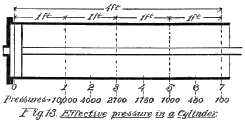
As stated in a preceding chapter the work done is estimated in foot pounds. For the purpose of more easily comprehending the manner in which the steam acts, and the value obtained by expansion, let us take a cylinder, such as is shown in Fig. 13, and assume that it has a stroke of four feet. Let the cylinder have a diameter of a little less than one foot, so that by using steam at fifty pounds pressure on every square inch of surface, we shall have a pressure of about 5000 pounds on the piston with live steam from the boiler.
In the diagram the piston moves forwardly to the right from 0 to 1, which represents a distance of one foot, so that the full pressure of the steam of the boiler, representing 5000 pounds, is exerted on the piston. At 1 the steam is cut off, and the piston is now permitted to continue the stroke through the remaining three feet by the action of the steam within the cylinder, the expansive force alone being depended on.
As the pressure of the steam within the cylinder is now much less and decreases as the piston moves along, we have taken a theoretical indication of the combined pressure at each six inch of the travel of the piston. The result is that we have the following figures, namely, 4000, 2700, 1750, 1000, 450 and 100. The sum of these figures is 10,000 pounds.
The piston, in moving from 0 to 1, moved one foot, we will say, in one second of time, hence the work done by the direct boiler pressure was 5000 foot pounds; and since the piston was moved three feet more by the expansion of the steam only, after the steam pressure was shut off, the work done in the three seconds required to move the piston, was an additional 5000 foot pounds, making a total of 10,000 foot pounds for four seconds, 150,000 foot pounds per minute, or about 45 horse power.
This movement of the piston to the right, represented only a half revolution of the crank, and the same thing occurs when the piston moves back, to complete the entire revolution.
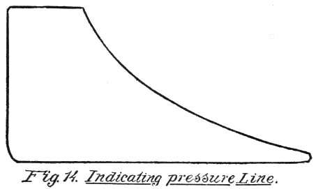
Indicating the Engine.—We now come to the important part of engine testing, namely, to ascertain how much power we have obtained from the engine. To do this an indicator card must be furnished. A card to indicate the pressure, as we have shown it in the foregoing diagram would look like Fig. 14.
The essential thing, however, is to learn how to take a card from a steam engine cylinder, and we shall attempt to make this plain, by a diagram of the mechanism so simplified as to be readily understood.
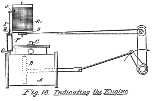
In Fig. 15 we have shown a cylinder A, having within a piston B, and a steam inlet pipe C. Above the cylinder is a drum D, mounted on a vertical axis, and so geared up with the engine shaft that it makes one complete turn with each shaft revolution. A sheet of paper E, ruled with cross lines, is fixed around the drum.
The cylinder A has a small vertical cylinder F connected therewith by a pipe A, and in this cylinder is a piston H, the stem I of which extends up alongside of the drum, and has a pointed or pencil J which presses against the paper E.
Now, when the engine is set in motion the drum turns in unison with the engine shaft, and the pressure of the steam in the cylinder A, as it pushes piston B along, also pushes the piston H upwardly, so that the pencil point J traces a line on the ruled paper.
It will be understood that a spring is arranged on the stem I in such a manner that it will always force the piston H downwardly against the pressure of the steam.
Mean Efficiency.—We must now use a term which expresses the thing that is at the bottom of all calculations in determining how much power is developed. You will note that the pressure on the piston during the first foot of its movement was 10,000 pounds, but that from the point 1, Fig. 13, to the end of the cylinder, the pressure constantly decreased, so that the pressure was not a uniform one, but varied.
Suppose we divide the cylinder into six inch spaces, as shown in Fig. 13, then the pressure of the steam at the end of each six inches will be the figures given at bottom of diagram, the sum total of which is 30,000, and the figures at the lower side show that there are eight factors.
The figure 10,000 represents, of course, two six inch spaces in the first foot of travel.
The result is, that, if we divide the sum total of the pressures at the eight points by 8, we will get 3750, as the mean pressure of the steam on the piston during the full stroke of the piston.
In referring to the foot pounds in a previous paragraph, it was assumed that the piston moved along each foot in one second of time. That was done to simplify the statement concerning the use of foot pounds, and not to indicate the time that the piston actually travels.
Calculating Horse Power.—We now have the first and most important factor in the problem,—that is, how much pressure is exerted against the piston at every half revolution of the crank shaft. The next factor to be determined is the distance that the piston travels in one minute of time.
This must be calculated in feet. Let us assume that the engine turns the crank shaft at a speed of 50 revolutions a minute. As the piston travels 8 feet at each revolution, the total distance traveled is 400 feet.
If, now, we have a constant pressure of 3750 pounds on the piston, and it moves along at the rate of 400 feet per minute, it is obvious that by multiplying these two together, we will get the figure which will indicate how many pounds the steam has lifted in that time.
This figure is found to be 1,500,000, which means foot pounds, as we have by this means measured pressure by feet, or pounds lifted at each foot of the movement of the piston.
As heretofore stated, we must now use the value of a horse power, so that we may measure the foot pounds by it. If we had a lot of wheat in bulk, and we wanted to determine how much we had, a bushel measure would be used. So with power. The measure, as we have explained, is 33,000, and 1,500,000 foot pounds should give as a result a little over 45 horse power.
Condensation.—We now come to the refinements in engine construction,—that which adds so greatly to the economy of operation. The first of these is condensation. The first reciprocating engine depended on this to do the actual work. In this age it is depended upon simply as an aid.
The first thing however that the engineer tries to do is to prevent condensation. This is done by jacketing the outside of the cylinder with some material which will prevent radiation of heat, or protect the steam within from being turned back into water by the cool air striking the outside of the cylinder.
Atmospheric Pressure.—On the other hand, there is a time when condensation can be made available. The pressure of air on every square inch of surface is 143/4 pounds. When a piston moves along and steam is being exhausted from the cylinder, it must act against a pressure of 143/4 pounds on every square inch of its surface.
The problem now is to get rid of that back pressure, and the old type engines give a hint how it may be done. Why not condense the steam discharged from the engine cylinder? In doing so a vacuum is produced on the exhaust side of the piston, at the same time a pressure is exerted on its other side.
The Condenser.—Thus the condenser is brought into existence, as an aid. By jacketing condensation is prevented; it is fought as an enemy. It is also utilized as a friend. It is so with many of the forces of nature, where man for years vainly fought some principle, only to find, later on, that a friend is more valuable than a foe, and to utilize a material agency in nature is more economical than to fight it.
Pre-heating.—The condenser does two things, both of which are of great value to the economical operation of the engine. For the purpose of rapidly converting the steam back into water as it issues from the engine cylinder, water is used. The steam from the cylinder has a temperature of 212 degrees and upwards, dependent on its pressure.
Water, ordinarily, has a temperature of 70 degrees, or less, so that when the steam strikes a surface which is cooled down by the water, it is converted back into liquid form, but at a temperature less than boiling water. The water thus converted back from the steam gives up part of its heat to the water which cools the condenser, and the water from the condenser, as well as the water used to cool the condenser, are thus made available to be fed into the boiler, and thus assist in again converting it into a steam.
The economy thus lies in helping the coal, or other fuel, do its work, or, to put it more specifically, it conserves the heat previously put out by the coal, and thus saves by using part of the heat over again.
Superheaters.—Another refinement, and one which goes to the very essence of a heat motor, is the method of superheating the steam. This is a device located between the boiler and the engine, so that the steam, in its transit from the boiler to the engine, will be heated up to a high degree, and in the doing of which the pressure may be doubled, or wonderfully increased.
This may be done in an economical manner in various ways, but the usual practice is to take advantage of the exhaust gases of the boiler, in the doing of which none of the heat is taken from the water in the boiler.
The products of combustion escaping from the stacks of boilers vary. Sometimes the temperature will be 800 degrees and over, so that if pipes are placed within the path of the heated gases, and the supply steam from the boiler permitted to pass through them a large amount of heat is imparted to the steam from a source which is of no further use to the water being generated in the boiler.
Compounding.—When reference was made to the condensation of steam as it issued from the boiler, no allusion was made to the pressure at which it emerged. If the cylinder was well jacketed, so that the amount of condensation in the cylinder was small, then the pressure would still be considerable at the exhaust. Or, the steam might be cut off before the piston had traveled very far at each stroke, in which case the exhaust would be very weak.
In practice it has been found to be most economical to provide a high boiler pressure, and also to superheat the steam, but where it is not superheated, and a comparatively high boiler pressure is provided, compounding is resorted to.
To compound steam means to use the exhaust to drive a piston. In such a case two cylinders are placed side by side, one, called the high pressure cylinder, being smaller than the low pressure cylinder, which takes the exhaust from the high pressure.
The exhaust from the second, or low pressure cylinder may then be supplied to a condenser, and in that case the mechanism would be termed a compound condensing engine. If a condenser is not used, then it is simply a compound engine.
Triple and Quadruple Expansion Engines.—Instead of using two cylinders, three, or four, are employed, each succeeding cylinder being larger than the last. As steam expands it loses its pressure, or, stated in another way, whenever it loses pressure it increases in volume. For that reason when steam enters the first cylinder at a pressure of say 250 pounds, it may exhaust therefrom into the next cylinder at a pressure of 175 pounds, with a corresponding increase in volume.
To receive this increased volume, without causing a sensible back pressure on the first cylinder, the second cylinder must be larger in area than the first; in like manner when it issues from the exhaust of the second cylinder at 125 pounds pressure, there is again an increase in volume, and so on.
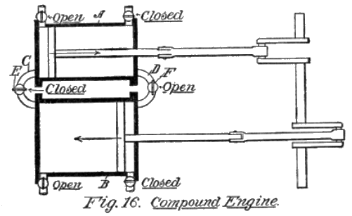
Examine Fig. 16, which shows a pair of cylinders, A being the high, and B the low pressure cylinders, the exhausts of the high pressure being connected up with the inlets of the low pressure, as indicated by the pipes, C D.
The diagram does not show the valve operations in detail, it being sufficient to explain that when the valve E in the pipe C is closed, the valve F, at the other end of the cylinders, in the pipe D, is closed. The same principle is employed in the triple and quadruple expansion engines, whereby the force of the steam at each exhaust is put to work immediately in the next cylinder, until it reaches such a low pressure that condensation is more effective than its pressure.
The diagram, as given, is merely theoretical, and it shows the following factors:
First: The diameter of each piston.
Second: The area of each piston in square inches.
Third: The steam pressure in each cylinder.
Fourth: The piston pressure of each cylinder.
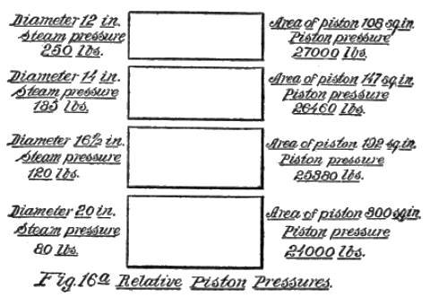
It will be seen that an engine so arranged is able to get substantially the same pressure in each of the second, third and fourth cylinders, as in the first (see Fig. 16a), and by condensing the discharge from the fourth cylinder a most economical use of steam is provided for. The Steam Turbine.—We must now consider an entirely new use of steam as a motive power. Heretofore we have been considering steam as a matter of pressure only, in the development of power. It has been observed that when the pressure of steam decreases at the same temperature it is because it has a greater volume, or a greater volume results.
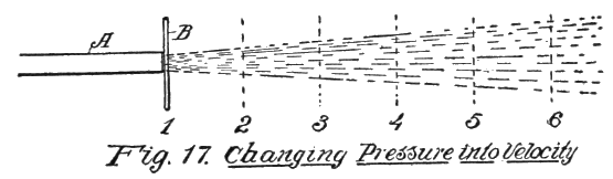
When steam issues from the end of a pipe its velocity depends on its pressure. The higher the pressure the greater its velocity. The elastic character of steam is shown by its action when ejected from the end of a pipe, by the gradually enlarging area of the discharging column.
In a reciprocating engine the power is derived from the pressure of the steam; in a turbine the power results from the impact force of the steam jet. Such being the case velocity in the movement of the steam is of first importance.
Pressure and Velocity.—To show the effectiveness of velocity, as compared with pressure, examine Fig. 17. A is a pipe discharging steam at a pressure of 100 pounds. To hold the steam in the pipe would require a pressure of 100 pounds against the disk B, when held at 1, the first position.
Suppose, now, the disk is moved away from the end of the pipe to position 2. The steam, in issuing forth, strikes the disk over a larger area, and in escaping it expands, with the result that its velocity from 1 to 2 is greater than the movement of the steam within the pipe that same distance.
The disk is now moved successively to positions 3, 4, 5, and so on. If we had a measuring device to determine the push against the disk at the various positions, it would be found that there is a point at some distance from the end of the pipe, at which the steam has the greatest striking force, which might be called the focal point.
A blow pipe exhibits this same phase; the hottest point is not at the end of the pipe, but at an area some distance away, called the focal point of heat.
The first feature of value, therefore, is to understand that pressure can be converted into velocity, and that to get a great impact force, the steam must be made to strike the hardest and most effective blow.
When a jet of steam strikes a surface it is diverted or it glances in a direction opposite the angle at which it strikes the object. In directing a jet against the blades of a turbine it is impossible to make it strike squarely against the surface.
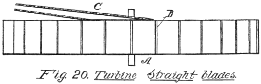
Let us assume that a wheel A, Fig. 20, has a set of blades B, and a steam jet is directed against it by the pipe C. It will be seen that after the first impact the steam is forced across the blades, and no further force is transferred to them.
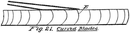
Form of Blades.—The blades are therefore so curved, that the steam after the first impact cannot freely pass along the blade, as it does on a straight blade, but imparts on every element of the curved-back blade, thereby giving up continually part of its speed to the blade.
This is clearly shown in Fig. 21, where the pipe D ejects the stream of steam against the concaved blades E. Many modifications have been made in the shapes of these blades, all designed to take advantage of this action.
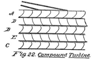
Compounding the Jet.—We may extend the advantages gained by this form of blades, and diverting the course of the jet, so that it will be directed through a series of wheels, each of which will get the benefit of the moving mass from the pipes.
Such a structure is shown in Fig. 22, in which three bladed wheels A, B, C, are caused to rotate, a set of stationary blades D, E, being placed between the three moving wheels, but the stationary blades are disposed in reverse directions. When the steam from pipes F, F, impinges against the blades of the first wheel A, it is directed by the stationary blade D to the next wheel B, and from the stationary blade E to the blades of the next wheel C, thus, in a manner somewhat similar to the compounding effect of the steam engine, utilizes the pressure which is not used at the first impulse.
CHAPTER IV
FUELS AND COMBUSTION
All fuels must be put into a gaseous state before they will burn. This is true of coal as well as of hydro-carbon oils.
Neither coal nor petroleum will burn in its native state, without the addition of oxygen. This is absolutely necessary to support combustion. Burning is caused by the chemical union of oxygen with such substances as will burn.
This burning process may be slow, and extend over a period of years, or it may be instantaneous, in which latter case the expansion of the heated gases is so great as to cause an explosion. When a sufficient amount of oxygen has been mixed with a fuel to permit it to burn, a high temperature is necessary to cause the immediate burning of the entire mass.
If such a temperature is not present the course of combustion is not arrested, but it will, on its own account, start to oxydize, and eventually be reduced to the same condition that would take place if exploded by means of a flame.
Solid Fuels.—The great fuels in nature are carbon and hydrogen, carbon being the substance most widely known and depended upon. Hard coal, for instance, is composed almost wholly of carbon; whereas soft coal has a considerable quantity of hydrogen.
As coal was formed by wood, which, through long process of time became carbonized, it contains considerable foreign matter which will not burn, forming ash.
Liquid Fuels.—The volatile oils, however, have very little non-combustible matter. Ordinary petroleum contains about 80 per cent, of carbon, and from 12 to 15 per cent. of hydrogen, the residue being foreign matter, all more or less susceptible of being consumed at high temperatures.
Combustion.—The term combustion, in its general sense, means the act of burning; but in a larger and more correct application it refers to that change which takes place in matter when oxygen unites with it.
Oxygen is a wonderful element, and will unite with all known substances, unlike all other elements in this respect. It may take years for it to form a complete unity. Thus, wood, in time, will crumble, or rot, as it is called. This is a slow process of combustion, brought about without applying heat to it, the change taking place in a gradual way, because oxygen unites with only a small portion of the wood.
Oxidation.—Iron will rust. This is another instance of combustion, called oxidation. When oxygen unites with a substance it may produce an acid, or an alkali, or a neutral compound. When wood is burned it produces an ash, and this ash contains a large amount of potash, or lye, which is an alkali, or a salt. So when other substances are burnt the result may be an acid, like sulphur, or it may be unlike either acid or the alkali.
The unity of oxygen with the food in the body is another instance of oxidation, which produces and maintains the heat necessary for existence.
Carbon or hydrogen, as a fuel, are inert without oxygen, so that in considering the evolution of a force which is dependent on heat, we should know something of its nature, thereby enabling us to utilize it to the best advantage.
The Hydro-carbon Gases.—If petroleum, or gasoline, should be put into the form of a gas, and as such be confined in a receiver, without adding any oxygen, it would be impossible to ignite it.
The character of the material is such that it would instantaneously extinguish any flame. Now, to make a burning mixture, at least three parts of oxygen must be mixed with one of the hydro-carbon, before it is combustible.
Oxygen and Atmosphere.—The atmosphere is not oxygen. Only one-fifth of common air is oxygen, the residue being, principally, nitrogen, which is not a fuel. To produce the proper aëration, therefore, at least fifteen parts of air must be mixed with one part of hydro-carbon gas.
The term hydro-carbon is applied to petroleum, and its products, because the elements carbon and hydrogen make up the largest part of the oil, whereas this is not the case with most of the other oils.
We are now dealing with a fuel such as is needed in Internal Combustion Engines, and it is well to know some of the problems involved in the use of the fuel, as this will give a better understanding of the structure of the devices which handle and evolve the gases, and properly burn them within the engine.
Vaporizing Fuel.—As the pure liquid will not burn in that state the first essential is to put it into a gaseous form, or to generate a vapor from it. The vapor thus made is not a gas, in the true sense of that term, but it is composed of minute globules of finely-divided particles of oil.
Nearly all liquids will vaporize if permitted to come into contact with air. The greater the surface exposed to air the more rapidly will it turn into a vapor.
By forcibly ejecting the liquid from a pipe or spraying device, and mingling air with it, evaporation is facilitated, and at the same time the proper admixture of air is provided to make a combustible substance the moment sufficient heat is brought into contact with it.
This is what actually takes place in a gasoline engine, and all the mechanism is built with this end in view.
It has been the universal practice to make an explosive mixture of this character, and then ignite it by means of an electric spark, but it is now known that such a fuel can be exploded by pressure, and this needs some explanation.
Explosion by Compression.—The study of the compressibility of gases is an interesting one. As we have previously stated, the atoms, comprising the gases, are constantly moving among themselves with great rapidity, so that they bombard the sides of the receiver in which they are confined, and also contact with each other in their restless movements.
When compression takes place the speed of the movements of the atoms is greatly accelerated, the friction of their movements is increased, and heat is evolved. As the pressure becomes greater the heat increases until it is of such intensity that the gas ignites, and an explosion follows.
How Compression Heats.—The theory of the compressibility of gases may be stated as follows: Let us assume that the temperature of the air is 70 degrees Fahrenheit, and we have a receiver which holds two cubic feet of this air.
If the contained air is now compressed to a volume of one cubic foot, the temperature of two cubic feet is compressed into one cubic foot, and there is now 140 degrees of heat within the receiver.
If this cubic foot of air is again compressed to half its volume, the temperature is correspondingly increased. While this it not absolutely true in practice, owing to the immense loss caused by radiation, still, it will enable the mind to grasp the significance of compression, when the subject of heat is concerned.
Elasticity of Gases.—The great elasticity of gases, and the perfected mechanical devices for compressing the same, afford means whereby ten or twenty atmospheres can be forced into a receiver, and thereby produce pressures of several hundred pounds, which would mean sufficiently high temperatures to ignite oils having the higher flash point.
Advantages of Compression.—The compression system permits of the introduction of a larger quantity of fuel than is usually drawn into the cylinder, and thereby a greater and more efficient action is produced on the piston of the engine on account of quicker combustion and therefore higher gas pressures.
The compression, however, rarely if ever exceeds six atmospheres or about 90 pounds per square inch.
The Necessity of Compression.—There are two reasons why compression is necessary before igniting it. First, because it is essential to put sufficient gas in the cylinder to make the engine efficient.
To illustrate: Suppose we have a cylinder capable of drawing in 150 cubic inches of gas, and this is compressed down to 25 cubic inches, the space then occupied by the gas would represent what is called the clearance space at the head of the cylinder. To compress it to a greater degree the clearance space might be made smaller, which could be done in several ways, but whether the gas thus drawn in should be compressed to 30, or 25, or even 10 cubic inches, it is obvious that there would be no more fuel in the cylinder in one case than in the other. As however the mean effective pressure, which determines the efficiency of the motor, increases with the compression pressure, the latter should be as high as possible, but not so high that premature explosion takes place owing to the heat created by compression.
Second: The more perfect the mixture of the vaporized product with the air, the more vigorous will be the explosion. The downward movement of the piston draws in the charge of air and sprayed jet of gasoline, and the only time for mixing it is during the period that it travels from the carbureter through the pipes and manifold to the cylinder.
Having in mind the statement formerly made that compression causes a more rapid movement of the molecules of a gas, it is obvious that the upward movement of the piston, in the act of compressing the gas has a more positive action in causing an intimate mixture of the hydro-carbon gases than took place when the gases were traveling through the pipes on their way to the cylinder.
CHAPTER V
THE INTERNAL COMBUSTION ENGINE
It will be observed that in a steam engine the heat is developed outside of the cylinders and the latter used solely for the purpose of taking the steam and utilizing it, by causing its expansion to push a piston to and fro.
We shall now consider that type of motor which creates the heat within the cylinder itself and causes an expansion which is at once used and discharged at the reciprocating motion of the piston.
The original method of utilizing what is called Internal combustion Motors, was to employ a fixed gas. A fixed gas is one which will remain permanently in that condition, unlike a vapor made from gasoline. The difference may be explained as follows:
Fixed Gases.—If the vapor of gasoline, or petroleum, is subjected to a high heat, upwards of 1500 degrees, it is so changed chemically, that it will not again return to a liquid state. This is called fixing it. Gas is made in that way from the vapor of coal, and fixed, producing what is called illuminating gas.
Although the temperature of fixing it is fully three times greater than is required to explode it, the fact that it is heated in closed retorts, and oxygen is prevented from mixing with it, prevents it from burning, or exploding.
Gas Engines.—Such a gas has been used for many years in engines which were usually of the horizontal type, and were made exceedingly heavy and cumbrous, and provided with enormous fly wheels. Gases thus made are not as rich as those generated direct from the hydro-carbon fuels, because, being usually made from coal they did not have a large percentage of hydrogen.
Energy of Carbon and Hydrogen.—When a pound of carbon is burned, it develops 14,500 heat units, and a pound of hydrogen over 52,000 heat units. Assuming that 85 per cent. of a pound of petroleum is carbon, and 15 per cent. is hydrogen, the heat units of the carbon would be 12,225, and the heat units of the 15 per cent. of hydrogen would be 12,800. The combined value is, therefore, 25,025, which is almost double that of coal gas.
This fact makes the gasoline engine so much more efficient, and for the same horse power the cylinders can be made smaller, and the whole structure much lighter in every way.
Gasoline motors are of two types, one in which an explosion takes place at every revolution of the crank, called the two-cycle, and the other the four-cycle, in which the explosion occurs at every other turn of the crank.
The terms two-cycle is derived from the movement of the piston, as that moves downwardly during the period when the crank is making a half turn, and returns in its upward stroke when the crank completes the turn, or that two half turns of the crankshaft complete the cycle. Four-cycle engines have two such complete movements at each impulse, or require four half turns of the crankshaft to complete the cycle.
The Two-Cycle Type.—In order to clearly distinguish between this and the four-cycle, it would be well to examine the diagram, Fig. 23. For a clearer understanding the drawing is explained in detail.
The cylinder A, within which the piston works, has a removable cap B, and at its lower end a removable crank case C. The case is designed to entirely close the lower end of the cylinder so that it is air tight, for reasons which will be explained.
The outer jacket, or casing D, at the upper end of the cylinder, is designed to provide a space E, for the circulation of water, to cool the cylinder during its working period. The crankshaft F passes through the crank case, the latter having suitable bearings G for taking care of the wear.
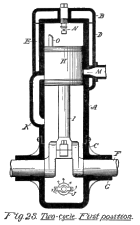
The piston H is connected up with the rod I, the latter being hinged at a point within the piston, as shown. The crank case has an inlet port, provided with a valve which opens inwardly, so that when the piston moves upwardly the valve will open and air will be drawn into the crank case and space below the piston.
At one side is a vertical duct K, which extends from a point directly above the crank case, to such a position that when the piston is at its lowest point gas can be discharged into the space above the piston.
On the opposite side of the cylinder, and a little above the inlet port of the duct K, is a discharge port M. The inlet port and the discharge port, thus described, are both above the lower end of the piston when it is at its highest point.
The spark plug is shown at N. On the upper end of the piston, and close to the side wall through which the inlet port K is formed, is an upwardly-projecting deflecting plate O, the uses of which will be explained in the description of its operation.
Fig. 23 shows the piston at its highest point, and we will now assume that ignition takes place, thus driving the piston downwardly until the upper end of the piston has fully uncovered the discharge port M, as shown in Fig. 24. This permits the exhaust to commence, and as the piston proceeds down still further, so as to uncover the inlet port K, the gas, which at the down stroke has been compressed in the space below the piston, rushes in, and as it strikes the deflecting plate O, is caused to flow upwardly, and thus helps to drive out the burnt gases remaining at the upper end of the cylinder.
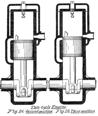
This action is called scavenging the cylinder, and the efficiency of this type of engine is largely due to the manner in which this is done. It is obvious that more or less of the unburnt gases will remain, or that some of the unburnt carbureted air will pass out at each discharge, and thus, in either case, detract from the power of the subsequent explosion.
As the piston now moves upwardly to complete the cycle, the piston closes both of the ports, thus confining the gas which was previously partly compressed, and as the piston proceeds the gas is still further compressed until the piston again reaches the upward limit of its motion.
Advantages of the Two-Cycle Engine.—This kind of engine has several distinct advantages. It has less weight than the four-cycle; it gives double the number of impulses for a given number of revolutions of the crankshaft; and it dispenses with valves, springs, cam-shafts, stems and push rods.
More or less danger, however, attends the operation of a two-cycle engine, principally from the fact that an explosive mixture in a partially compressed condition is forced into the space which the instant before was occupied by a flame, and it is only because the expansion of the burst gases at the previous charge has its temperature decreased so far below the explosion point, that the fresh gas is not ignited, although there have been occasions when explosions have taken place during the upstroke.
The Four-Cycle Engine.—The most approved type is that which is known as the four-cycle. This will also be fully diagrammed so as to enable us to point out the distinctive difference.
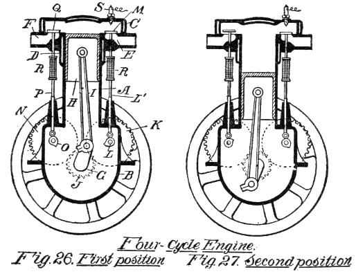
Figs. 26 and 27 show sections of a typical four-cycle engine, in which the inlet and the exhaust valves are mechanically operated. The cylinder A is either cast with or separate from the crank case B, and has a removable head C. The upper end of the cylinder has a water space formed by the jacket D.
The inlet port E and the discharge port F are both at the upper end of the cylinder. The crank shaft G passes horizontally through the crank case, and it is not necessary, as in the case of the two-cycle-engine, to have the case closed tight.
The piston H is attached to the connecting rod I, which is coupled to the crank, as shown. The crank shaft has a small gear J, which meshes with two gears of double size on opposite sides of the crank shaft, one of the gears K, being designed to carry the cam L for actuating the stem L´, which opens the valve M in the port that admits the carbureted air.
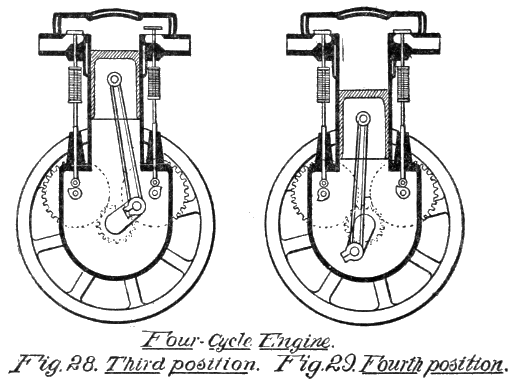
The other large gear N is mounted on a shaft which carries a cam O that engages the lower end of a push rod P, to open the valve Q in the discharge port F. It should be observed that the stems L´, P, are made in two parts, with interposing springs R, so the valves may be firmly seated when the stems drop from the cams.
The spark plug S is located in the head, close to the inlet port. The character of the igniting system is immaterial, as the object of the present diagrams is to show the cycle and method of operating the engine at each explosion, and to fully illustrate the manner in which it is distinguished from the two-cycle type.
A fly wheel is necessary in this as in the other type, and in practice the two gear wheels, K, N, are placed outside of the case B, and only the small gear, and the cam shafts, on which the cams are mounted, are within the case.
The operation is as follows: In Fig. 26 the piston is shown in a position about to commence its downward movement, and we will assume that the ignition has just taken place. Both valves M, Q, are closed, as it will be noticed that the cams L, O, are not in contact with the lower ends of the push rods.
The explosion drives the piston down to the position shown in Fig. 27, when the cam O begins to raise the stem P, and thus opens the discharge valve Q, permitting the burnt gases to escape as the piston travels upwardly to the position shown in Fig. 28.
At this position the valve Q closes, and the cam L opens the inlet valve M, so that as the piston descends the second revolution, the carbureted air is drawn in until the crank has just turned at its lowest limit of movement, as shown in Fig. 29.
The upward stroke of the piston now performs the work of compressing the carbureted air in the cylinder, and it is ready for the ignition the moment it again reaches the position shown in Fig. 26.
The Four Cycles.—The four distinct operations thus performed are as follows: First, the explosion, and downward movement of the piston. Second, the upward movement of the piston, and the discharge of the burnt gases. Third, the down stroke of the piston, and the indrawing of a fresh charge of carbureted air. Fourth, the upward movement of the piston, and the compression of the charge of carbureted air.
The order of the engine performance may be designated as follows: 1. Impulse. 2. Exhaust. 3. Admission. 4. Compression.
Ignition Point.—While the point of ignition, shown in the foregoing diagrams, represents them as taking place after the crank has passed the dead center, the firing, in practice, is so adjusted that the spark flashes before the crank turns past the dead center.
The reason for this will be apparent on a little reflection. As the crank turns very rapidly the spark should be advanced, as it is called, because it takes an interval of time for the spark to take effect and start the explosion. If the sparking did not take place until the crank had actually passed the dead center, the full effect of the compression and subsequent explosion pressure would not be had.