Front matter (continued 2)
Reading edition
Advantage of the Four-Cycle Type.—The most marked advantage in the four-cycle type is its efficiency. As it has one full stroke within which to exhaust the burnt gases, the cylinder is in a proper condition to receive a full value of the incoming charge, and there is no liability of any of the unburnt gases escaping during the exhaust from the previous explosion.
The next important advantage of this type is in the fact that it can be operated at a higher speed than the two-cycle type, and this is a great advantage, notwithstanding the less number of impulses in the four-cycle type.
The Loss in Power.—The great disadvantage in all engines of this class is the great loss resulting from their action. The explosion which takes place raises the temperature to fully 2000 degrees of heat, and unless some provision is made to keep the cylinder down to a much lower temperature the engine would soon be useless.
High temperatures of this character absolutely prevent lubrication, a thing which is necessary to insure proper working. For this reason a water jacket is provided, although there are engines which are cooled by the action of air.
In any event, the heat imparted to the cylinder is carried away and cannot be used effectively, so that fully one-half of the power is dissipated in this direction alone.
The next most serious loss is in the escape of heat through the burnt gases, which amounts to seventeen per cent. If the expansive force of the burnt gases at the time of ignition is 250 pounds per square inch, and at the time of the discharge it is fifty pounds, only four-fifths of its power is effectively used.
As, however, the discharge is against the air pressure of nearly fifteen pounds per square inch, it is obvious that thirty-five pounds per inch is driven away and lost.
The third loss is by conduction and radiation, which amounts to fifteen per cent. or more, so that the total loss from all sources is about eighty-four per cent., leaving not more than sixteen per cent. of the value of the fuel which is converted into power.
Engine Construction.—In the construction of engines the utmost care should be exercised in making the various parts. The particular features which require special care are the valves, which should be ground to fit tightly, the proper fitting of the piston rings, crank shaft and connecting rod bearings as well as the accurate relining of these bearings.
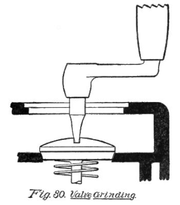
Valve Grinding.—Fig. 30 shows a valve and valve seat. The valve has usually a cross groove so that a screw driver in a drill stock may be used to turn it and to exert the proper pressure. The finest emery powder and a first class quality of oil should be used. The valve is seated and after the oil and emery powder are applied the drill stock is used to turn the valve.
After twenty or thirty turns, wipe off the parts and examine the contact edges, to see whether the entire surfaces are bright, which will indicate that the valve fits true on its seat. Never overgrind. This is entirely unnecessary. It is better also to rock the crank of the drill stock back and forth, instead of turning it in one direction only.
The Crank Shaft.—The crank shaft is the most difficult part of the engine to build. It is usually made of a single forging of special steel and the cranks and bearings are turned out of this, requiring the utmost care. Formerly these were subject to breakage, but improved methods have eliminated all danger in this direction.
The Cams.—Notwithstanding the ends of the push rods are provided with rollers to make the contact with the cams, the latter will wear, and in doing so they will open the valves too late. The slightest wear will make considerable difference in the inlet valve, and it requires care and attention for this reason, in properly designing the cams, so that wear will be brought to a minimum.
CHAPTER VI
CARBURETERS
A carbureter is a device which receives and mixes gasoline and air in proper proportions, and in which a vapor is formed for gasoline engines.
The product of the carbureter is a mixture of gasoline vapor and air, not a gas. A gas, as explained, is of such a character that it remains fixed and will not stratify or condense.
Functions of a Carbureter.—The function of a carbureter is to supply air and gasoline by means of its adjustable features so as to make the best mixture. The proportions of air and gasoline will vary, but generally the average is fifteen parts of air to one of gasoline vapor.
If there is too much gasoline, proportionately, a waste of fuel results, as a great amount of soot is formed under those conditions. If there is an excess of air the mixture, when ignited, will not have such a high temperature, hence the expansive force is less, and the result is a decrease of power.
While it is possible to get a rapid evaporation from gasoline by heating it, experience has shown that it is more economical to keep the gasoline cool, or at ordinary temperatures, provided the carbureter is properly constructed, because the vapor, if heated, when drawn into the engine, will be unduly expanded, and less fuel in that case is drawn in at each charge, and less power results.
Rich Mixtures.—There are conditions under which rich mixtures are advantageous. This is a mixture in which there is a larger percentage of gasoline than is necessary for instantaneous combustion. For ordinary uses such a mixture would not be economical.
At low speeds, however, or when carrying heavy loads, it is desirable, for the reasons that at a slow speed the combustion is slower.
Rich mixtures are objectionable at high speeds because, as the combustion is slow, incomplete combustion within the power stroke results, the temperature of the gas at the end of the stroke is very high, and this will seriously affect the exhaust valves. Furthermore, there is likelihood of the gas continuing to burn after it is discharged from the cylinder.
Lean Mixtures.—Such a mixture is one which has a less amount of gasoline than is necessary to make a perfectly explosive compound. For high speeds a lean mixture is desirable, principally because it burns more rapidly than a rich mixture.
Types of Carbureters.—There are two distinct types of carbureters, one which sprays the gasoline into a conduit through which air is passing, and the other in which a large surface of gasoline is placed in the path of the moving air column, which was originally used, but has been absolutely replaced by the jet carbureters on account of their better control features.
It will be remembered that reference was made to the manner in which vaporization takes place, this term being used to designate that tendency of all liquids to change into a gaseous state. All carbureters are designed with the object of mechanically presenting the largest possible area of oil to the air, so that the latter will become impregnated with the vapor.
The Sprayer.—The best known type depends on dividing up the gasoline into fine globules, by ejecting it from a small pipe or jet. The spray thus formed is caught by the air column produced by the suction of the engine pistons, and during its passage through the throttle and the manifold, is in condition where a fair mixture of air and vapor is formed, which will readily ignite.
The Surface Type.—This form of carbureter provides a pool of gasoline with a large surface, within the shell, so arranged that as the air is drawn past the pool it must come into contact with the oil, and thus take up the necessary quantity of evaporated gasoline for charging the air.
The surface type has not been used to a large extent, but the sprayer is universally used, and of this kind there are many examples of construction, each having some particular merit.
Governing a Carbureter.—It is a curious thing that one carbureter will work admirably with one engine, and be entirely useless in another. This is due to several factors, both in the engine design and in the carbureter itself. The quality of mixture that an engine will take depends on its speed. The suction of the pistons depends on the speed of the engine.
If, at ordinary speed the carbureter gives a proper mixture, the throats and passages through the pipes and manifold, as well as the valve which discharges the gasoline, may be in a prime condition to do good work; but when the pistons work at double speed the inrush of air may not carry with it the proper amount of fuel; or, under those conditions, the air may receive too great an amount of gasoline, proportionally.
The latter is usually the case, hence provision must be made for such a contingency, and we shall therefore take up the various features essential in the construction of the carbureter, so as to show what steps have been taken to meet the problems arising from varying speeds, differences in the character of the fuel, regulating the inflow and mixture of gasoline and air, and adjustments.
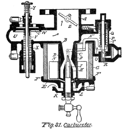
So many different types of carbureters have been devised, that it is difficult to select one which typifies all the best elements of construction.
In Fig. 31 we have shown a well known construction, and which will illustrate the features of the sprayer type to good advantage. The body of the device, represented by A, has a flange by means of which it is secured to the pipe which carries the carbureted air to the engine. The lower end of this tubular body is contracted, as shown at B, so as to form what is called a venturi tube.
Exteriorly this contracted tube is threaded, as shown at C, so as to receive thereon a threaded body D, the lower end of the body having an enlarged disk-head E, integral therewith, and an upwardly-projecting annular flange F is formed around this disk to receive and hold a cylinder G, which constitutes the float and fuel chamber.
The upper end of this cylinder rests against a seat cast with the body A, and packing rings are placed at the ends of the cylinder to prevent the oil from leaking out. Within the tubular body D is a vertical tube H, integral with the disk head E, and oil is supplied to this tube through ducts I, which communicate with the chamber within the reservoir G.
A drain cock is at the lower end of this tube, and an adjustable cap K screws on the tubular stem of the drain tube, around which air is admitted, the air passing upwardly through vertical ducts L, as shown, and thus mixes with air at the contracted part of the venturi tube.
A ring-like float N is placed within the glass chamber, and this is adapted to engage with the inner end of a lever N´, this lever being pivoted at O, within a side extension P of the carbureter shell. The inner end of this lever has a link hinged thereto, the lower end of which serves as a needle valve to close the ejecting orifice of the tube L.
The outer end of the lever N´ engages a shoulder on a vertically-disposed needle valve Q, which has its point in the inlet opening of the pipe R, through which gasoline is supplied to the glass chamber. A spring T serves to keep the valve stem normally on its seat.
Directly opposite this chambered extension P is another extension U, also cast with the shell, through which is a vertical stem V. This stem carries a downwardly-opening valve W, that seats against a plug, and a spring X below the valve, serves to keep it against its seat, unless there should be an extraordinarily heavy pull or suction.
This is the auxiliary air inlet, and the lower spring is actuated only when the engine is running at moderate speeds, but when running at high speed and an additional quantity of air is required the upper spring Y is compressed, and thus a much greater quantity of air is allowed to pass in and mingle with the spray at the throttle valve Z.
The throttle valve is mounted in the discharge opening, and is controlled by a lever on the outside of the carbureter.
The device operates as follows: Primary air enters the opening between the cup K and the disk-head E, passing up into the space around the oil tube H. As the spring T, around the needle valve Q, draws up the valve from its seat, oil is permitted to flow in through the duct R and fill the chamber, until the float engages with the inner end of the lever N, and raises it, thus uncovering the ejecting end of the tube H, and at the same time closing the inlet tube R.
The suction from the engine then draws air through the primary duct, as stated, and also an additional quantity through the secondary source, by way of the valve W, this valve being so regulated as to supply the requisite quantity.
The auxiliary air source serves the purpose that means should be provided to supply more than the ordinary amount of air, when running at high speeds.
From the foregoing it will be observed that a carbureter must be so constructed that it will perform a variety of work. These are: First, Automatic means for filling the float chamber when the gasoline goes below a certain level. Second, Cutting off the supply of gasoline. Third, Providing a primary supply of gasoline for spraying purposes. Fourth, Furnishing an auxiliary air supply. Fifth, Throttling means in the discharge opening.
It is thus a most wonderful contrivance, and considering that all the elements necessary to make it work satisfactorily are provided with adjustable devices, it may be seen that to make it perform correctly requires a perfect understanding of its various features.
Requirements in a Carbureter.—In view of the foregoing it might be well to know how to select a carbureter that is ideal in its operation.
First. The adjustment of the auxiliary valve should be of such a character that at the slowest speed the valve should not be lifted from its seat.
Second. It must be so arranged that it is not difficult to change the relative amount of air and gasoline.
Third. The floating chamber should be so arranged that the float will act on the lever which lifts the valve of the injecting pipe, even though the carbureter body should be tilted at an angle. This is particularly important when the carbureter is used in automobiles.
Fourth. The valves should be in such position that they are readily accessible for cleaning or for examination.
Fifth. The float should be so arranged that it is adjustable with reference to the lever that it contacts with.
Sixth. A gauze strainer should be placed at the gasoline inlet, and it is also advisable to have a similar strainer above the mixing chamber, beyond the throttle.
Seventh. There should be no pockets at any point in the body to hold the gasoline which might condense.
Eighth. The body of the carbureter should be so constructed that every part is easily accessible, and draining means provided so that every particle of gasoline can be withdrawn.
Ninth. Means for heating it, in case of cold weather.
Size of the Carbureter.—The proper size of a carbureter for an engine has been the subject of considerable discussion and experimenting. If its passages are too large, difficulty will be experienced in starting the engine, because the pulling draft through the primary will not be sufficient to make a spray that will unite with the air.
A carbureter too large will only waste fuel, even after the engine has been cranked up so it will start.
If the carbureter is too small the engine will not develop its required output of power. While it might work satisfactorily at low speeds it would be entirely inefficient at high speeds.
Rule for Size of Carbureter.—In all cases the valve opening and cylinder capacity in the engine should determine this. The size of the opening of the carbureter outlet should be the same as that of the engine valve, which is also the case where the carbureter supplies a multi-cylinder, as there is only one valve open at the same time.
It was formerly the custom to use a carbureter for each cylinder but the practice has been abandoned, because it is obvious that a single carbureter will, owing to the continuous suction, supply a mixture of more nearly uniform character than two or more, even though they should supply the mixture to a common manifold.
The Throttle.—Much of the economy in running an engine depends on the manipulation of the throttle. As an example, with a certain motor and carbureter it will be found that for maximum speed the throttle should be open about one-eighth of the way. The proper way, in starting the engine, is to open the throttle fully half way, and to retard the spark. As soon as the engine begins to run properly, the spark is advanced and the throttle closed down to the required point.
The engine speed may always be maintained by the throttle under a constant varying load, by adjusting the throttle valve. A rich mixture may be obtained by throttling the primary air supply.
The throttle may also be a most effective means of economizing fuel when the engine has a first class sparking device, as in that case the throttle can be closed down to provide a very small opening.
Flooding.—One of the most prevalent troubles in carbureters is the liability to flood. This is usually caused by foreign matter getting under or in the float valve, so that it will not properly seat. Sometimes the mere moving of the float will dislodge the particle.
Another cause of flooding is due, frequently, to an improperly-arranged float, which, when the engine is inclined, will prevent improper seating of the valve, and flooding follows.
The greatest care should be exercised in seeing that the gasoline supply is free from all impurities when it is poured into the tank. To strain it is the best precaution, and it pays to be particular in this respect. It is surprising to see the smallest speck, either stop the flow entirely, or produce an overflow, either of which will cause a world of trouble.
Water is another element which has no place in a carbureter. An indication of this is the irregular movement of the engine. The only remedy is to stop and drain the carbureter. A few drops may cause all the trouble.
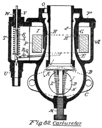
Types of Carbureters.—In Fig. 32 we show another type of carbureter, which is simple in construction, and has many desirable features. The cylindrical body of the carbureter, A, has a downwardly-projecting globular extension B, at one side of which is a flange C to secure it to the pipe, and through this is the discharge opening D. This globular extension serves as the mixing chamber.
Within the cylindrical shell is an upwardly-projecting circularly-formed extension E, and the top or cap F of the cylindrical body A has a downwardly-projecting cylindrical rim G which overlaps the lower circular extension E, and it is so constructed that a very thin annular slit H is thus formed between the two parts, through which fuel oil flows from the float chamber I into the space around the central tube J which passes down through the two circular extensions E, G.
This central tube J is designed for the auxiliary air supply. It extends down to the globular base B, and has a valve K seated against its end. The stem L of the valve is vertically-movable within an adjustable stem M, and a helical spring N, capable of having its tension adjusted by the stem M, bears upwardly against the valve so as to keep it normally against the lower end of the tube J.
The auxiliary air, therefore, passes down centrally through the tube J, while the primary air supply passes through openings O, surrounding the tube J, downwardly past the slitted opening H, and thence to the discharge port D.
Surrounding the tubular projections E, G, and within the float chamber I, is the float P. This is designed to strike the bifurcated ends of a lever Q, which is hinged near its outer end, as at R, and has its short projecting end resting beneath the collar of a vertical needle valve S.
This needle valve is vertically placed within a chambered extension T at the side of the shell A, and its lower end rests within the opening of the inlet U which supplies the gasoline to the chamber I. The upper end of the valve stem passes through a plug V, through which is a vent hole W.
A spring X is used between the plug and the collar on the lower end of the needle valve, so that the valve is kept on its seat thereby, unless the gasoline in the chamber should fall so low as to cause the float to rest on the inner end of the lever Q, when the needle valve would be unseated thereby.
All the parts of this device seem to be accessible, and it is presented as an example of construction that seems to meet pretty nearly all of the ideal requirements of a device for furnishing a perfect admixture.
Surface Carbureter.—This type of carbureter also requires a float but does not have secondary air inlet mechanism. It has one striking advantage over the sprayer system, in the particular that the suction of the engine is not depended upon to draw the gasoline from the float chamber. It is much more sensitive to adjustment in the float level and needle valve than the other type.
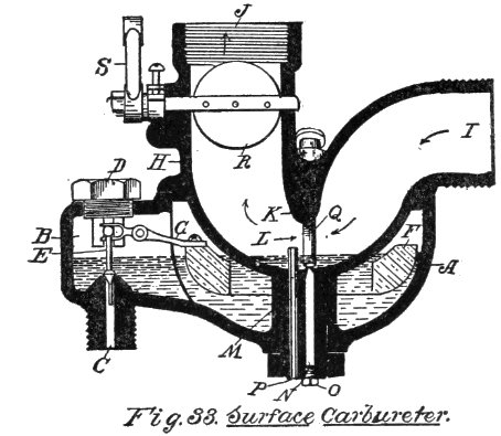
The diagram, Fig. 33, shows a body A, somewhat bowl-shaped, with a chambered extension, B, at one side, at the lower side of which is the fuel inlet duct C. Directly above this duct the upper wall of the extension has a plug D, the lower end of which carries therein the upper end of a vertically-movable needle valve, E, the lower end of the valve resting within the duct C.
A float F within the bowl-shaped body is secured at one side to a lever G, which is hinged at a point near the needle valve E, and the short end of this lever connects with this needle valve in such a manner that as the float moves upwardly the valve is seated, and when the level of the fuel oil falls below a certain point the needle is lifted from its seat, and oil is permitted to flow into the float chamber.
The cap H of the float chamber has cast therewith a U-shaped tube, the inlet end I being horizontally-disposed, while the discharge end J is vertical. Directly above the lowest part of the bend in this tube, the vertical dimension of the tube is contracted by a downwardly-projecting wall K, so as to form a narrow throat L.
Below this contracted point, the U-shaped tube has integral therewith a downwardly-projecting stem M, the lower end of which passes through an opening in the float chamber, and is threaded, so as to receive a nut, by means of which the cap H may be firmly fixed to the float chamber.
This stem M has a vertical duct N, which communicates with the float chamber, and is provided with a drain plug O. Alongside of this duct is a tube P which extends up into the U-shaped tube and is open at its lower end so that the level of the gasoline within the bent tube cannot extend above the end of this drain tube P.
An adjustable valve stem Q passes through one side of the bent tube, the lower end being pointed and adapted to regulate the inflow of gasoline through the duct N, and into the U-shaped tube.
A throttle valve R is placed in the discharge end of the U-shaped tube, which is susceptible of regulation by means of a lever S. The diagram shows the gasoline within the U-shaped tube, so that it is on a level with the gasoline in the float chamber.
In operation a sufficient amount of gasoline is permitted to enter the float chamber so that a pool is formed in the bottom of the U-shaped tube. When suction takes place the air rushes through the tube, at I, down beneath the wall K, and in doing so it sweeps past the surface of the pool at that point, absorbing a greater or less amount of the vapor.
In order to adjust the device so that a smaller amount of the liquid fuel will be exposed, the carbureter is adjusted so it will close the needle valve before the level of the liquid is so high, and thereby a less surface of oil is formed within the U-shaped tube.
It is obvious that this type of carbureter, owing to the absence of the secondary air-supply mechanism, can be readily regulated and all adjustments made while running, while for automobile uses the lever S, which controls the throttle, can be connected up with a dash-board control.
CHAPTER VII
IGNITION. LOW TENSION SYSTEM
Electricity, that subtle force, which manifests itself in so many ways, is nevertheless beyond the power of man to see. The only way in which we know of its presence is by the results produced by its movements, because it can make itself known to our senses only by some form of motion.
The authorities regard light, heat and electricity as merely different forms of motion. The most that can be done with such a force is to learn the laws governing it.
Magnetism.—This is a form of electricity. In fact, it is one of the most universal manifestations, for without it electricity would be useless. When the first permanent magnet was found at Magnesia, it was not considered electricity. The sciences had not arrived at that point where they were able to classify it as belonging to lightning and other manifestations of that kind which we now know to be electricity.
The Armature.—But magnetism can no more be seen than electricity flowing through a wire. If a piece of metal has magnetism it will attract a piece of iron or steel placed in close proximity, and thus we are permitted to see the action.
The lightning in the upper atmosphere burns the gases in its path. This enables us to see, not the current, but its action,—the result produced by its power.
The electric current has many peculiar manifestations, the causes of some of them being known and utilized. In the use of this medium for igniting the fuel gas, many of the phases of electrical phenomena are brought into play, and it is necessary, therefore, to know something of the fundamentals of the science to enable us to apply it.
Characteristics of Electricity.—When a current passes along a wire, it does not describe a straight path, but it moves around the conductor in the form of circles. The current is not confined wholly to the wire itself, but it extends out a certain distance from it at all points.
Magnetic Field.—Every part of a wire which is carrying a current of electricity has, surrounding it, a magnetic field, of the same character, and to all intents and purposes, of the same nature as the magnetic field at the ends of a magnet.
Elasticity.—This current has also something akin to elasticity. That is, it surges to and fro, particularly when a current is interrupted in the circuit. At the instant of breaking a current in an electric light circuit there is a momentary flash which is much brighter than the normal light, which is due to the regular flow of the current.
This is due to the surging movement, or the elastic tension, in the current. Advantage is taken of this characteristic, in making a spark. This spark is produced at the instant that the ends of the wires are separated.
The Make and Break System.—No spark is caused by putting the two ends together, or by making the connection, but only by breaking it, hence it is termed the make and break method of ignition.
When the connection is broken the current tries to leap across the gap, and in doing so develops such an intense heat that the spark follows. As a result of the high temperature it is necessary to use such a material where the gap is formed that it will not be burned. For this purpose platinum, and other metals are now employed.
Voltage.—This plays an important part in ignition. Voltage is that quality which gives pressure or intensity to a current. It is the driving force, just as a head of water gives pressure to a stream of water.
High and Low Voltage.—A high tension current,—that is, one having a high voltage, will leap across a gap, whereas a low voltage must have an easy path. When the ends of a wire in a circuit are separated, air acts as a perfect insulator between them, and the slightest separation will prevent a low current from jumping across.
This is not the case with a high tension current, where it will leap across and produce the flash known as the jump spark.
Low Tension System.—Two distinct types of ignition have grown out of the voltage referred to, in which the make and break system uses the low tension, because of its simplicity in the electrical equipment.
Disadvantages of the Make and Break.—There is one serious drawback to the extended use of this system, and that is the necessity of using a moving part within the cylinder, to make and break the contact in the conductor, as it is obvious that this part of the mechanism must be placed within the compressed mixture in order to ignite it.
Amperes.—A current is also measured by amperes,—that is, the quantity flowing. A large conductor will take a greater quantity of current than a small one, just as in the case of water a large pipe will convey a greater amount of the liquid.
Resistance.—All conductors offer resistance to the flow of a current, and this is measured in Ohms. The best conductor is silver and the next best is copper, this latter material being used universally, owing to its comparative cheapness.
Iron is a relatively poor conductor. Resistance can be overcome to a certain extent, however, if a large conductor is used, but it is more economical to use a small conductor which has small resistance, like copper, than a heavy conductor, as iron, even though pound for pound the latter may be cheaper.
Direct Current.—There are two kinds of current, one which flows in one direction only, called the Direct. It is produced in a dynamo which has a pair of commutator brushes so arranged that as the armature turns and its wires move through the magnetic fields of a magnet, and have direction of the current alternate, these brushes will change the alternations so the current will travel over the working conductors in one direction only.
Primary and secondary batteries produce a direct current. These will be described in their appropriate places.
Alternating Current.—This is a natural current. All dynamos originally make this kind of current, but the commutator and brushes in the direct current machine change the output method only. The movement of this current is likened to a rapid to and fro motion, first flowing, for an instant, to one pole, and then back again, from which the term alternating is derived.
While the sudden breaking in a circuit will produce a spark with either the direct or the alternating currents, the direct is usually employed for the make and break system, since batteries are used as the electrical source.
On the other hand the jump spark method employs the alternating current, because the high tension can be most effectively produced through the use of induction coils, which will be explained in connection with the jump spark method of ignition.
Generating Electricity.—There are two ways to produce a current for operating an ignition system, one by a primary battery, and the other by means of a magneto, a special type of dynamo, which will be fully explained in its proper place.
Primary Battery.—As we are now concerned with the make and break system, the battery type of generation, and method of wiring up the same, should first be explained.
Thus, in Fig. 34, a primary battery is shown, in which the zinc cell A has an upwardly-projecting wing B at one side, to which the conductor is attached; and within, centrally, is a carbon bar C. An electrolyte, which may be either acid or alkali, must be placed within the cell.
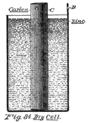
Making a Dry Cell.—The zinc is the negative, and the carbon the positive electrode. The best material for the electrolyte is crushed coke, which is carbon, and dioxide of manganese is used for this purpose, and the interstices are filled with a solution of sal-ammoniac.
The top of the cell is covered with asphaltum, so as to retain the moistened material and the liquid within the cell, and thus constituted, it is called a dry cell.
Energy in a Cell.—A battery is made up of a number of these cells. Each cell has a certain electric energy, usually from one and a half to one and three-quarter volts, and from twenty-five to forty amperes.
The amperage of a cell depends on its size, or rather by the area of the electrodes; but the voltage is a constant one, and is not increased by the change, formation, or size of the electrodes.
For this reason the cells are used in groups, forming, as stated, a battery, and to get efficient results, various methods of connecting them up are employed.
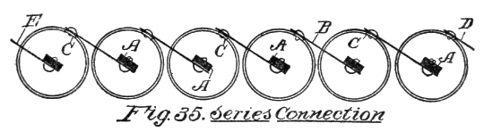
Wiring Methods.—As at least six cells are required to operate a coil, the following diagrams will show that number to illustrate the different types of connections.
Series Connection.—The six cells, Fig. 35, show the carbon electrodes A, of one cell, connected by means of a wire B with the zinc electrode wing C of the next cell, and so on, the cell at one end having a terminal wire D connected with the zinc, and the cell at the other end a wire E connected with the carbon electrode.
The current, therefore, flows directly through the six cells, and the pressure between the terminal wires D, E, is equal to the combined pressure of the six cells, namely, 11/2 × 6, which is equal to 9 volts. The amperage, however, is that of one cell, which, in these diagrams, will be assumed to be 25.
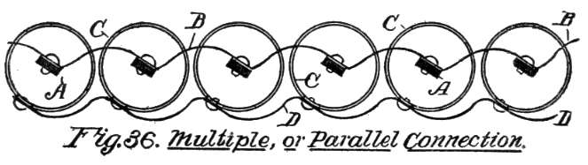
Parallel Connection.—Now examine Fig. 36. In this case the carbon electrodes A are all connected up in series, that is, one following the other in a direct line, by wires B, and the zinc electrodes C, are, in like manner, connected up in series with each other by wires D. The difference in potential at these terminals B, D, is the same as that of a single cell, namely, one and a half volt.
The amperage, on the other hand, is that of the six cells combined, or 150. This method of connecting the cells is also called parallel, since the two wires forming the connections are parallel with each other, and remembering this it may be better to so term it.
Multiple Connections.—This is also designated as series multiple since the two sets of cells each have the connections made like the series method, Fig. 35. The particular difference being, that the zinc terminals of the two sets of cells are connected up with one terminal wire A, and the carbon terminals of the two sets are joined to a terminal B.
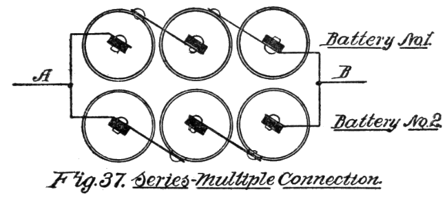
The result of this form of connection is to increase the voltage equal to that of one cell multiplied by the number of cells in one set, and the amperage is determined by that of one cell multiplied by the two sets.
Each set of cells in this arrangement is called a battery, and we will designate them as No. 1, and No. 2. Each battery, therefore, being connected in series, has a voltage equal to 41/2 volts, and the amperage 50, since there are two batteries.
Now the different arrangement of volts and amperes does not mean that the current strength is changed in the batteries or in the cells. If the pressure is increased the flow is lessened. If the current flow, or the quantity sent over the wires is increased, the voltage is comparatively less.
Watts.—This brings in another element that should be understood. If the current is multiplied by the amperes a factor is obtained, called Watts. Thus, as each cell has 11/2 volts and 25 amperes, their product is 371/2 watts.
To show that the same energy is present in each form of connection let us compare the watts derived from each:
Series connection: 9 volts × 25 amperes, equal 225 watts.
Parallel connection: 11/2 volts × 150 amperes, equal 225 watts.
Series Multiple connection: 41/2 volts × 50 amperes, equal 225 watts.
From the foregoing, it will be seen that the changes in the wiring did not affect the output, but it enables the user of the current to effect such changes that he may, for instance, in case a battery should be weak, or have but little voltage, so change connections as to temporarily increase it, although in doing so it is at the expense of the amperage, which is correspondingly decreased.
It would be well to study the foregoing comparative analysis of the three forms of connections, so far as the energy is concerned, because there is an impression that increasing the voltage, is adding to the power of a current. It does nothing but increase the pressure. There is not one particle of increase in the energy by so doing.
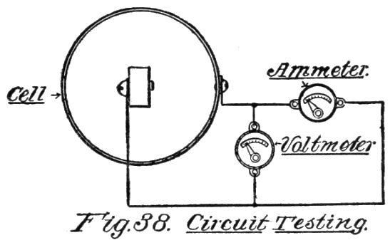
Testing a Cell.—The cells should be frequently tested, to show what loss there is in the amperage. This is done by putting an ammeter in the circuit. If a meter of this kind is not handy, a good plan is to take off one of the wire connections, and snap the wire on the terminal, and the character of the spark will show what energy there is in the cell.
Testing With Instruments.—The method of testing with voltmeter and ammeter, is shown in Fig. 38. The voltmeter is placed in a short circuit between the two terminal wires, whereas the ammeter is placed in circuit with one of the wires. The reason for this is that the voltmeter registers the pressure, the power, or the difference of potential between the two sides of the cell, and the ammeter shows the quantity of current flowing over the wire.
In practice batteries are not used continuously for igniting. They are temporarily employed, principally for starting, because their continued use would quickly deplete them.
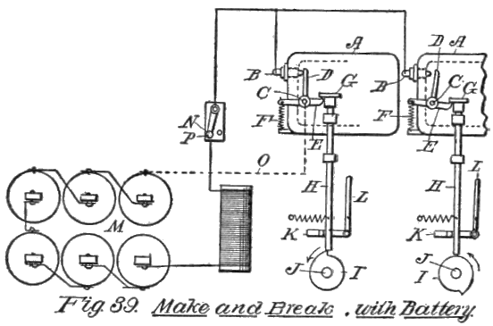
Simple Battery Make and Break System.—In order to show this method in its simplest form, examine Fig. 39, which diagrams the various parts belonging to the system.
We have illustrated it with two cylinders, portions of the heads being shown by the outlines A, A. B, B represent terminals which project into the cylinders, and are insulated from the engine heads. Through the sides of the engine heads are rock shafts C, the ends within the cylinder having fingers D which are adapted to engage with the inner ends of terminals B, B.
On the ends of the rock shafts outside of the cylinders, they are provided with levers E, E, one end of each being attached to a spring F, so that the tension of the spring will normally keep the upper end of the finger D in contact with the terminal B. The cut shows one finger engaging with B, and the other not in contact.
The other end of the lever E rests beneath a collar or shoulder G on a vertical rod H. The lower end of this rod engages with a cam I on a shaft J, and when the cam rotates the rod drops off the elevated part of the cam, and in doing so the shoulder G strikes the end of the lever E and causes the finger to rapidly break away from the terminal B, where the spark is produced.
To Advance the Spark.—For the purpose of advancing or retarding the spark, this rod has, near its lower end, a horizontally-movable bar K, which may be moved to and fro a limited distance by a lever L, this lever being the substitute in this sketch of the lever on the steering wheel of an automobile.
The spark is advanced or retarded by causing the lower end of the rod H to be moved to the left or to the right, so that it will drop off of the raised portion of the cam earlier or later.
The wiring up is a very simple matter. The battery M has one end connected up with one terminal of a switch N, while the other terminal of the switch has a wire connection with the terminal plugs B, B, in the cylinder heads.
The other end of the battery is connected with the metal of the engine, which may be indicated by the dotted line O which runs to the rock shaft C, and thus forms a complete circuit.
The operation is as follows: When the key P of the switch is moved over so that it contacts with the terminal N, the battery is thrown into the circuit, and the current then passes to the plug B of the first cylinder, as the finger D in that cylinder is in contact with that terminal, and it passes along the finger D, and rock-shaft C, to the metal of the engine, and passes thence to the battery, this course being indicated by the dotted line O.
At the same time, while cylinder No. 2 is also connected up with the battery, the shoulder of the rod H has drawn the finger D from its contact with the plug B, hence the current cannot pass in that direction.
As the cam I, of cylinder No. 1, turns in the direction of the arrow, the rod drops down and suddenly makes a break in the terminal of this cylinder, causing the ignition, to be followed by a like action in No. 2.
The Magneto in the Circuit.—To insure the life of the battery, so that it may be in service only during that period at the starting, when the magneto is not active, the latter is so placed in the circuit, that, at the starting, when, for instance, the automobile is being cranked, it is cut out by the switch on the dash board.
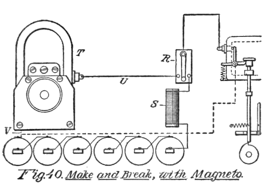
In Fig. 40, a simple two-pole switch is used. With the magneto it is necessary to have a three-point switch, R, and a plain coil S is placed between the switch and battery.
One side of the magneto T is connected by wire U with one of the points of the switch R, and the other side of the magneto is connected with the metal of the engine, which is indicated by the dotted line V.
In all other respects the mechanism is the same. The starting operation has been explained with reference to the preceding figure, and when the engine has picked up, and is properly started, the switch bar is thrown over so it contacts with the point connected up with the wire U leading to the magneto.
This, of course, cuts out the battery, and the engine is now running on the magneto alone. The object of the coil S is to oppose a rapid change of the current at the moment of the interruption. The coil induces a counter current the moment the break is made, and as the current continues to flow for a very short period after the break a spark of greater intensity is produced than if the circuit should be permitted to go from the battery to the sparker directly, as in the previous illustration.
The best spark is produced by quickly making the break between the points B, D, so that particular attention has been given to mechanism which will do this effectively.
Magneto Spark Plug.—One of the devices to obviate the difficulty of providing moving mechanism outside of the engine cylinder, is shown in Fig. 41. In this the coil A is connected with a terminal B at the head of the device and the other is connected to the plug C which screws into the cylinder head.
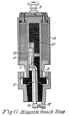
Within the core is a pivotally-mounted lever D, the upper end E of which is attracted by the tubular metallic core F, and the lower end having a contact point G, which is adapted to engage with a stationary point H.
The pivot I, on which the lever D is mounted, provides a means whereby the lever swings, and a spring J is so arranged that when the lower end of the lever is disengaged from the contact, the spring will return it to its normal position.
In its operation when a contact is formed by the timing device of the magneto, so as to give a spark, the circuit passes to the terminal B, coil A, and plug C, thus forming a complete circuit. This energizes the core A, pulling the upper end of the lever, and at the same time causes the lower end to disengage the two contacts G, H, which breaks the circuit and produces a spark.
The breaking of the circuit deënergizes the core, and the spring again draws the lever back to its normal position, ready for the next completion of the circuit by the timing device.
Such an arrangement is as simple as the spark plug usually employed in the use of the high tension system, although it is more expensive than the plug.
CHAPTER VIII
IGNITION. HIGH TENSION
This system is used to the largest extent, so that we ought to have a full explanation of the devices which are required to do the work. While magnetos are used with the low tension system, for the reasons stated, they are especially necessary with the Jump Spark method.
Magnetos.—The most important element in this system is the magneto, so we shall try and make the subject as explicit as possible. As stated, a magneto is a special type of dynamo which will now be explained. For this purpose it will be necessary to show the elementary operation of an alternating current dynamo.
Alternating Current.—In Fig. 42 A is a bar of soft iron, around which is a coil of wire B, the wire being insulated, so that it will not touch the bar. There is no magnetism in this bar, and this simple form of structure is shown, merely to represent what is called the field of a dynamo.
The object of the coil of wire is to make a magnet of the bar, for the moment a current is sent over the wire, a magnet is formed, and the magnetism leaves the bar the moment the current ceases to flow. If this bar should be of hard steel it would retain the magnetism.
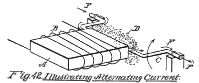
Now, the primary difference between the magneto and the dynamo, is that this field bar is a permanent magnet in the magneto, whereas the field is only a temporary magnet in the dynamo. This should always be kept in mind.
The end of a magnet, whether it is a temporary one, or permanent, has a magnetic field of force at the ends as well as at all parts of it, exterior to the surface of the bar. Such a field is indicated, and in the dynamo, no such field exists unless a current is passing over the wire B, which is called the field winding.
The U-shaped piece of metal C represents the armature. It is shown hinged to the top of two posts, for clearness in understanding, and is adapted to turn to the right, and in turning the loop passes the end of the field bar B, and passes through the magnetic field which is indicated by the dotted lines D.
Now, if the loop is simply permitted to remain in the position shown in Fig. 42, a current would flow through the loop, this transference of the current being called induction, and this characteristic of the flow of electricity will be explained and its utility explained.
Cutting Lines of Force.—The loop will now be turned to the right so that it passes the magnetic field and goes beyond it in its revolution. This motion of passing the armature through the magnetic field is called cutting the lines of force. While the loop was lying within the magnetic field, and also when it was moving through the field, the current set up in the loop flowed in the direction of the darts F, or to the right, through the pivots D.
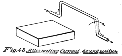
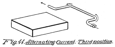
In Fig. 43 the loop is shown as having made a quarter turn, and it is now vertical, or at right angles to its former position. The loop in thus passing away loses its force, until it reaches the position shown in Fig. 44, when there is a surging back of the current to the opposite direction, as indicated by the arrows.
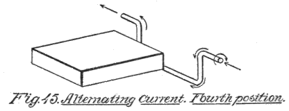
When the loop reaches the lowest position, shown in Fig. 45, it again begins to get the influence of the magnetic field, and a reversal back to its former direction takes place, this surging movement back and forth being due to the reversal of the polarity in the coil brought about by the position in which it is placed relative to the magnetic field.
It is now an easy matter to connect the ends of the loop with wire conductors. This is shown in Fig. 46, where a small metal wheel G is placed on each end of the spindle, and in having a strip of metal bearing H on the wheel. These are not commutator brushes, but are merely wiping brushes to take the current from the turning parts. Wires I connect with these wiping bars, and through them the current is transmitted to perform the work.
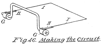
Plurality of Loops.—The dynamo may have a plurality of loops, which are called coils, and there may be a single magnet or any number of magnets. Instead of driving these coils past the face of the magnet, or magnets, the latter may be driven past the coils. In fact with most of the alternating current machines the fields are the rotating parts and the armatures, or the coils, are fixed.
The voltage is increased if the coils have a large number of turns on the armature, and also if the armature, or the turning part, is speeded up. Voltage will also be higher if larger or more powerful magnets are used in the magnetos.
The Electro-Magnet.—The permanent magnet, such as is used in the magneto, is distinguished by the fact that it contains a permanent charge of magnetism, but this is not an electro-magnet. This is a magnet made of soft iron, so it will be readily demagnetized. While not shown in the diagrams, an iron core may be placed within the loop or coil, and this is done in all dynamos, because the iron core acts as a carrier of the magnetism, concentrating it at the center, because it is a much better conductor than air.
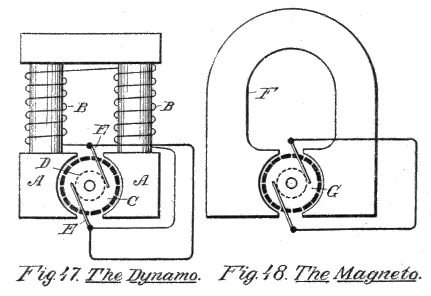
The Dynamo Form.—Consult the diagram, Fig. 47. The iron heads A represent the bar in the previous diagrams, and B the wire around the bar. C is the armature, which in this case represents a number of loops, or coils, and D is the commutator, which is used in the direct current machine to correct the alternations referred to in the previous diagrams, so as to send the current in one direction only, the commutator brushes E being used to carry off the current for use.
The Magneto Form.—The metal loop F, in Fig. 48, being a permanent magnet, the armature, G, formed of a plurality of loops, has no field wires to connect with it, as in the case of the dynamo.
Advantage of the Magneto.—The magneto has a pronounced advantage over the dynamo, as a source of power for ignition purposes, in the particular that the strength of the magnetic field is constant. In a dynamo this varies with the output, because when used on an automobile where the speed is irregular, the voltage will vary. The voltage of the magneto is a constant one, and is thus better adapted to meet the needs of ignition.
Induction Coil.—The induction coil is a device which is designed to produce a very high voltage from a low tension, so that a current from it will leap across a gap and make a hot spark.
We stated in a previous section that a current leaps across from one conductor to another, so that electricity can be transferred from a wire to another not touching it, by means of induction.
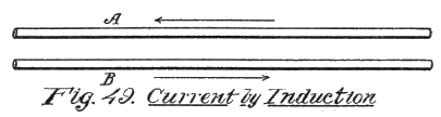
Look at Fig. 49, which represents two wires side by side. The current is flowing over one wire A, and by bringing wire B close to A, but not touching it, a current will be induced to leap across the gap and the wire B will be charged. If the ends of the wire B are brought together, so as to form a circuit, and a current detector is placed in the circuit it will be found that a current is actually flowing through it, but it is now moving in a direction opposite to the current flowing through A.
Changing the Current.—But we have still another thing to learn. If the two wires are not of the same thickness it would not prevent the current from leaping across, but another astonishing thing would result.
First, we shall use a wire B double the thickness of wire A. If now, we had an instrument to test the voltage and the amperage, it would be found that the voltage in B is less than that in A, and also that the amperage is greater.
Second, if the conditions are reversed, and the wire A is thicker than B, the latter will have an increase of voltage, but a lower ampere flow than in A.
Now this latter condition is just what is necessary to give a high tension. Voltage is necessary to make a current leap across a gap. By this simple illustration we have made an induction coil which may be used for making a high tension jump spark.
Construction of a Coil.—Two wires side by side do not have the appearance of a coil, and even though such an arrangement might make a high tension current, it would be difficult to apply. To put the device in such a shape that it can be utilized, a spool is made, as shown in Fig. 50.
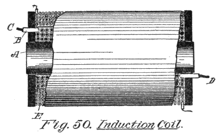
This spool A has a number of layers of thick, insulated wire B first wound around it, the layers being well insulated from each other, and the opposite ends brought out at one end or at the opposite ends, as shown at C, D. On this is a layer of finer wire, also insulated, this wire E having its terminals also brought out at the ends of the spool, and after the whole is thus wound, the outside of the coil is covered with a moisture proof material.
The Primary Coil.—The winding of thick wire is called the primary coil. The current from the battery or the electric generator is led to this inner coil.
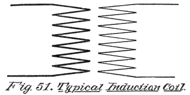
The Secondary Coil.—The fine wire wrapping represents the secondary coil, which is raised to a high voltage, and this actuates the sparking mechanism.
In the art it is customary to illustrate the various contrivances by certain conventional forms. Fig. 51 shows the manner of designating an induction coil in a diagram, in which the heavy zig-zag line indicates the primary, and the lighter zig-zag lines the secondary coil.
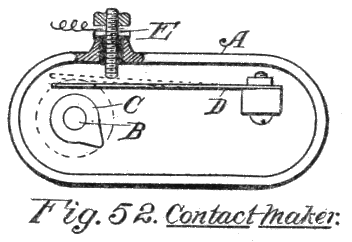
Contact Maker.—A simple little device used in the primary circuit of an induction coil, is known as a contact maker. This, as shown in Fig. 52, is merely a case A, through which is a shaft B that carries within the shell a cam C. A spring finger D has its free end normally bearing against the cam, and when the nose on the cam moves out the spring finger, the latter is moved outwardly so it contacts with a plug E in the side wall of the case, although it is insulated therefrom. This contact establishes a current through the plug, spring finger and case.
The diagram, Fig. 53, illustrates the principles of construction and arrangement of a high tension jump spark ignition, in which the electrical source is a battery actuating an induction coil.
High Tension With Battery and Coil.—The battery A has one side connected up by wire B with one terminal of the primary C in the induction coil, and the other side of the battery has a wire D leading to the contact maker. A switch E is placed in the line of this wire.
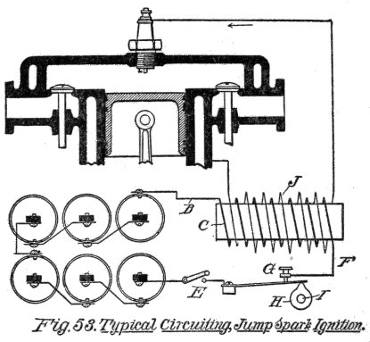
The other terminal of the primary has a wire F leading to the insulated contact plug G of the contact maker. This completes the generating circuit. The cam H is on a shaft I, which travels one half the speed of the engine shaft.
One side of the secondary coil J has a wire K leading to the spark plug, while the other terminal of the secondary has a wire L which is grounded on the engine M.
When the nose of the cam pushes over the spring finger and closes the cam, the circuit through the finger flows through the primary coil and excites the secondary. When the cam again immediately breaks the circuit a high tension current is momentarily induced in the secondary, so that the current leaps the gap in the spark plug and makes the spark.
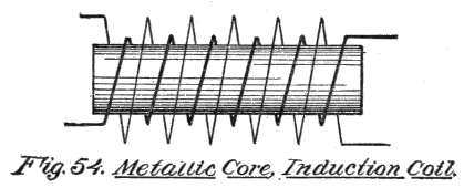
Metallic Core for Induction Coil.—In the previous description of the induction coil it was stated that the spool might be made of wood. These coils are also provided with metal cores, which can be used to make what is called a vibratory coil.
The Condenser.—A necessary addition to the circuiting provided by an induction coil, is a condenser. This is used in the primary circuit to absorb the self-induced current of the primary and thus cause it to oppose the rapid fall of the primary current.
The condenser is constructed of a number of tinfoil sheets, of suitable size, each sheet having a wing at one end, and these sheets are laid on top of each other, with the wings of the alternate sheets at opposite ends. Very thin sheets of waxed paper are placed between the tin foil sheets so that they are thus insulated from each other.
The wings at the ends are used to make connections for the conducting wires. The device is not designed to conduct electricity, but to act as a sort of absorbent, if it might so be termed. The large surface affords a means where more or less of the current moves from the conductor at one end to the conductor at the other end, and as it is designed to absorb a portion of the current in the line it is merely bridged across from one side of the circuit to the other.
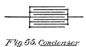
The diagram, Fig. 55, represents the conventional form of illustrating it in sketching electrical devices.
Operation of a Vibrator Coil.—The illustration, Fig. 56, shows the manner in which a vibrator coil is constructed and operated. The coil comprises a metal core A, the primary winding B being connected at one terminal, by a wire C, with a post D, and the other terminal by a wire E with one side of a battery F. A switch G is in the line of this conductor.
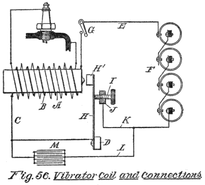
The post D holds the end of a vibrating spring H, which has a hammer H´ on its free end, which is adapted to contact with the end of the metal core A, but is normally held out of contact, so that it rests against the end of an adjusting screw I which passes through a post J.
The post J is connected up with the battery by a wire K, and a wire L also runs from the wire K to the conductor C, through a condenser M.
The secondary coil N, has the outlet wires O, P, which run to the spark plug Q on the engine.
The operation is as follows: When the switch G closes the circuit, the battery thus thrown in the primary coil magnetizes the core A, and the hammer H´ is attracted to the end of the core, thus breaking the circuit at the contact screw I. The result is that the core is immediately demagnetized, and the spring H draws the hammer back to be again attracted by the core which is again magnetized, so that the hammer on the vibrator arm H goes back and forth with great rapidity.
From the foregoing explanations it will be understood how the primary induces a high tension current in the secondary, and in order that the spark may occur at the right time, a timer for closing and opening the primary circuit must be provided. By this means an induced high tension current is caused to flow at the time the spark is needed in the cycle of the engine operation.
The Distributer.—The distributer is a timing device which controls both the primary and the secondary currents, and it also has reference to the revolving switch on the shaft of a magneto whereby the current is distributed to the various cylinders in regular order.
Fig. 57 shows a form of distributer which will illustrate the construction. A is the shaft which is driven at one half the engine speed. It is usually run by suitable gearing direct from the shaft of the magneto.
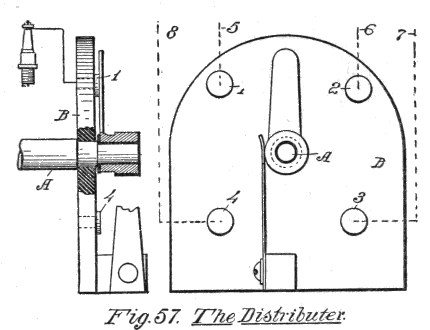
Its outer end rests in a bearing plate B, of insulating material, which plate serves as the disk to hold the contact plates, 1, 2, 3, 4, to correspond with the four cylinders to which the current is to be distributed.
Wires 5, 6, 7, and 8, run to the respective spark plugs C from these contact plates. The projecting end of the shaft A carries thereon a contact finger D, which is designed to contact with the respective plates, and an insulating ring E is interposed between the shaft and finger so as to prevent short circuiting of the high tension current.
On the side of the finger is a hub F, integral therewith, and a wiper attached to a post bears against the hub so as to form continuous contact. A wire leads from the post to one terminal of the secondary coil.
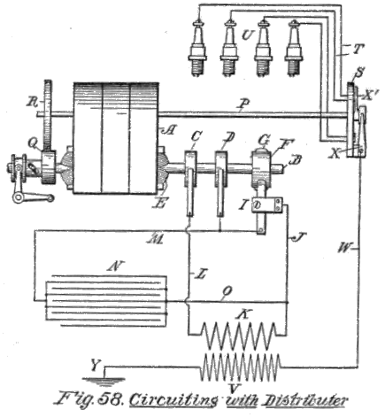
Circuiting With Distributer.—The diagram Fig. 58 shows the complete connections of a system which comprises a magneto, induction coil, condenser, and a distributer. The magneto A has on its armature shaft B two revolving disks C, D, one of which must be insulated from the shaft, and one end of the coil E of the armature is connected with one of these disks, and the other end of the coil is attached to the other disk.
Alongside of these disks is another disk F which has projecting points G to engage with and make temporary contact with a spring finger which actuates the interrupter I, this being a contact breaker which breaks the primary current at the time a spark is required.
One terminal of this interrupter is connected by a wire J with one end of the primary winding K, of the induction coil, and the other end of the primary has a wire L which runs to the disk C.
The other terminal of the interrupter has a wire M leading to a condenser N, and from the other side of the condenser is a wire O leading to the wire J before described. The wiper of the other disk D has a wire connection with the wire M.
The distributer shaft P is so mounted that it may receive its motion from the shaft of the magneto, and for this purpose the latter shaft has a gear Q one half the diameter of the gear R on the distributer shaft.
The distributer S has been described with sufficient clearness in a preceding diagram, to show how the wires T lead therefrom and connect up with the spark plugs U. One terminal of the secondary coil V is connected by a wire W with the wiper X which contacts with the hub of the distributer finger X´, and the other terminal of the primary is grounded at Y, which represents the metal of the engine.
CHAPTER IX
MECHANICAL DEVICES UTILIZED IN POWER
One of the most important things in enginery is the capacity to determine the power developed. Although the method of ascertaining this appears to be somewhat complicated, it is really simple, and will be comprehended the more readily if it is constantly borne in mind that a certain weight must be lifted a definite distance within a particular time.
The Unit of Time.—The unit of time is either the second, or the minute, usually the latter, because it would be exceedingly difficult to make the calculations, or rather to note the periods as short as a second, and a very simple piece of mechanism to ascertain this, is to mount a horizontal shaft A, Fig. 59, in bearings B, B, and affix a crank C at one end.
It will be assumed that the shaft is in anti-friction bearings so that for the present we shall not take into account any loss by way of friction.
A cord, with one end attached to the shaft and the other fixed to a weight D, the latter weighing, say 550 pounds, is adapted to be wound on the shaft as it is turned by the crank.
Knowing the length of the cord and the time required to wind it up, it will be an easy matter to figure out the power exerted to lift the weight, which means, the power developed in doing it.
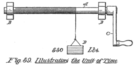
Suppose the cord is 100 feet long, and it requires one and a half minutes to raise the weight the full limit of the cord. It is thus raising 550 pounds 100 feet in 45 seconds.
One horse power means that we must raise 550 pounds one foot in one second of time, hence we have developed only 1/45th of one horse power.
Instead of using the crank, this shaft may be attached to the engine shaft so it will turn slowly. Then add sufficient weight so that the engine will just lift it, and wind the cord on the shaft.
You can then note the time, for, say, one minute, and when the weight is lifted, make the following calculation: Weight lifted one hundred feet in one minute of time was 825 pounds. Multiply 100 by 825, which equals 82,500. This represents foot pounds.
As there are 33,000 foot pounds in a horse power, 82,500 divided by this figure will show that 21/2 horse power were developed.
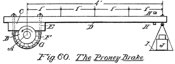
The Proney Brake.—Such a device is difficult to handle, but it is illustrated merely to show the simplicity of the calculation. As a substitute for this mechanism, a device, called the Proney brake has been devised, which can be used without rewinding of a cord. This is accomplished by frictional means to indicate the power, and by the use of weights to determine the lift.
The following is a brief description of its construction: The engine shaft A, Fig. 60, which is giving out its power, and which we want to test, has thereon a pulley B, which turns in the direction of the arrow. Resting on the upper side of the pulley is a block C, which is attached to a horizontal lever D by means of bolts E, these bolts passing through the block C and lever D, and having their lower ends attached to the terminals of a short sprocket chain F.
Block segments G are placed between the chain and pulley B, and when the bolts E are tightened the pulley is held by frictional contact between the block C and the segments G.
The free end of the lever has a limited vertical movement between the stops H, and a swinging receptacle I, on this end of the lever, is designed to receive weights J.
The first thing to do is to get the dimensions of the pulley, its speed, and length of the lever. By measurement, the diameter of the pulley is six inches. To get the circumference multiply this by 3.1416. The distance around, therefore, is a little over 18.84 inches. The speed of the pulley being 225 times per minute, this figure, multiplied by 18.84, gives the perimeter of the pulley 4239 inches.
As we must have the figures in feet, dividing 4239 by 12, we have 353.25 feet.
The length of the lever from the center of the pulley to the suspension point of the receptacle, is 4 feet, and this divided by the radius of the pulley (which is 6 inches), gives the leverage. One half of six inches, is three inches, or 1/4 of one foot, and 4 divided by this number, is 1' 4", or 11/3 feet, which is the leverage.
Now, let us suppose the weight J is 1200 pounds. This must be multiplied by the leverage, 11/3 feet, which equals 1800, and this must be multiplied by the feet of travel in the pulley, namely, 353.25, which is equal to 635,850. This represents foot pounds.
Now, following out the rule, as there are 33,000 foot pounds in a horse power, the foregoing figure, 635,850, divided by 33,000, equals 19 horse power within a fraction.
Reversing Mechanism.—A thorough knowledge of the principles underlying the various mechanical devices, and their construction, is a part of the education belonging to motors. One of the important structures, although it is very simple, when understood, requires some study to fully master.
This has reference to reversing mechanism, which is, in substance a controllable valve motion, whereby the direction of the valve is regulated at will.
All motions of this character throw the valve to a neutral point which is intermediate the two extremes, and the approach to the neutral means a gradual decrease in the travel of the valve until the reciprocating motion ceases entirely at the neutral position.
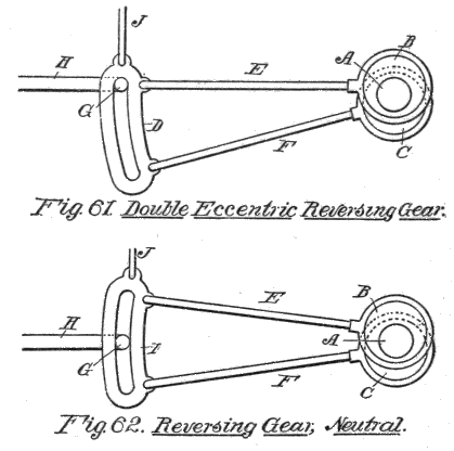
Double Eccentric Reversing Gear.—A well known form of gear is shown in Fig. 61, in which the engine shaft A has two eccentrics B, C, the upper eccentric B being connected with the upper end of a slotted segment D by means of a stem E, and the other eccentric C is connected with the lower end of the segment by the stem F. The eccentrics B, C, are mounted on the shaft so they project in opposite directions.
The slotted segment carries therewith the pin G of a valve rod H, and the upper end of the segment has an eye I, to which eye is a rod J operated by a lever.
By this arrangement the link may be raised or lowered, and as the valve rod pin has no vertical movement, either the connecting link E or F may be brought into direct line with the valve rod H.
Fig. 61 shows the first position, in which the valve rod H is in direct line with the upper connecting rod E, actuated by the cam B.
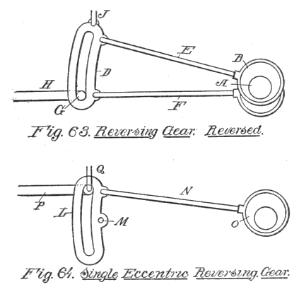
Fig. 62 shows the neutral position. Here the pin G serves as a fulcrum for the rocking movement of the segment; whereas in Fig. 63 the valve rod H is in line with the lower connecting rod F, so that the valve is pushed to and fro by the eccentric C.
It is more desirable, in many cases, to use a single eccentric on the engine shaft, which can be done by pivoting the segment L, Fig. 64, to a stationary support M, and connecting one end of the segment by a link N with the single eccentric O.
In this construction the valve rod P is shifted vertically by a rod Q, operated from the reversing lever, thus providing a changeable motion through one eccentric.
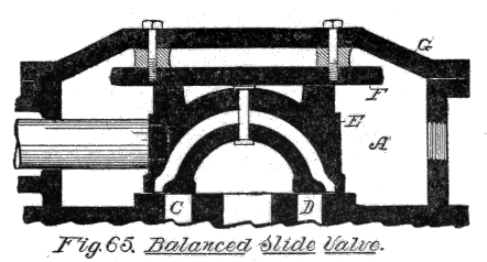
Balanced Slide Valves.—In the chapter pertaining to the steam engine, a simple form of slide valve was shown, and it was stated therein that the pressure of the steam bearing on the valve would quickly grind it down. To prevent this various types of balanced valves have been made, a sample of which is shown in Fig. 64.
The valve chest A has in its bottom two ports C, D, leading to the opposite ends of the cylinder, and within is the sliding valve E, which moves beneath an adjustable plate F connected with the top or cover G of the valve chest.
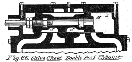
This is also modified, as shown in Fig. 66, in which case the slide valve H bears against the cover I at two points, so that as there is steam on the upper surface to a slightly greater area than on the lower side, there is sufficient downward pressure to hold it firmly on its seat, and at the same time not cause any undue grinding. This valve also has double exhaust ports J, J.
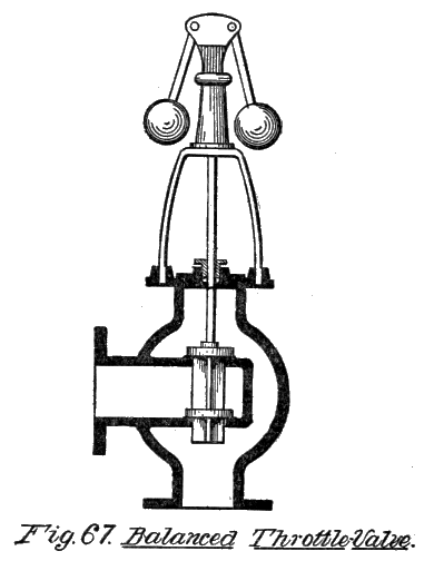
Balanced Throttle Valve.—Fig. 67 will give a fair idea of the construction of throttle valves, the illustration showing its connection with a simple type of governor.
Engine Governors.—Probably the oldest and best known governor for regulating the inlet of steam to an engine, is what is known as the Watt design. This is shown in Fig. 68.
The pedestal A which supports the mechanism, has an upwardly-projecting stem B, to the upper end of which is a collar C, to which the oppositely-projecting pendent arms D are hinged. These arms carry balls E at their free ends.
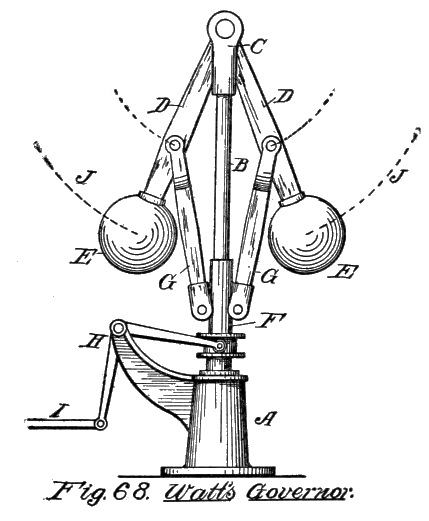
The lower part of the stem has thereon a sliding collar F, and links G, with their lower ends hinged to the collar, have their upper ends attached to the swinging arms D. The collar has an annular groove at its lower end, to receive therein the forked end of one limb of a bell-crank lever H, the other limb of this lever being connected up with the engine throttle, by means of a link L.
Centrifugal motion serves to throw out the balls, as indicated by the dotted lines J, and this action raises the bell-crank lever, and opens the throttle valve.
Numerous types of governors have been constructed, some of which operate by gravity, in connection with centrifugal action. Some are made with the balls adapted to swing downwardly, and thrown back by the action of springs. Others have the balls sliding on horizontally-disposed arms, and thrown back by the action of springs; and gyroscopic governors are also made which are very effective.
Fly wheel governors are not uncommon, which are placed directly on the engine shaft, or placed within the fly wheel itself, the latter being a well known form for engines which move slowly.
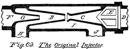
Injectors.—The Injector is one of the anomalies in mechanism. It actually forces water into a boiler by the action of the steam itself, against its own pressure. It is through the agency of condensation that it is enabled to do this.
The illustration, Fig. 69, which represents the original type of the device, comprises a shell A, within which is a pair of conically formed tubes, B, C, in line with each other, the small ends of the tubes being pointed towards each other, and slightly separated. The large end of the conical tube C, which points toward the pipe D, which leads to the water space of the boiler, has therein a check valve E.
The steam inlet pipe F, has a contracted nozzle G, to eject steam into the large end of the conical tube B, and surrounding the nozzle F is a chamber which has a pipe H leading out at one side, through which cold water is drawn into the injector.
Surrounding the conical pipes B, C, is a chamber I, which has a discharge pipe J. The action of the device is very simple. When steam is permitted to flow into the conical tube B, from the nozzle G, it passes out through the drain port J, and this produces a partial vacuum to form in the space surrounding the nozzle G.
As a result water is drawn up through the pipe H, and meeting with the steam condenses the latter, thereby causing a still greater vacuum, and this vacuum finally becomes so great that, with the inrushing steam, and the rapid movement through the conical tubes, past their separated ends, a full discharge through the drain J is prevented.
As it now has no other place to go the check valve E is unseated, and the cold water is forced into the boiler through the pipe D, and this action will continue as long as condensation takes place at the nozzle G.
Many improvements have been made on the original form, mostly in the direction of adjusting the steam nozzle, and to provide the proper proportion of flow between the steam and water, as this must be adjusted to a nicety to be most effective.
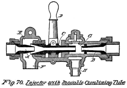
An example of a movable tube which closes the outlet to the overflow, is shown in Fig. 70. The steam inlet tube A is at one end of the shell, and the outlet tube B to the boiler, at the other end, and intermediate the two is a tube C, with its open flaring end adapted to receive the steam from the tube A. This tube is longitudinally-movable, so that the controlling lever D may move it to and fro.
A chamber E surrounds the nozzle A, and has a water inlet pipe F, while the space G between the ends of the pipes B, C, has an outlet H, a single check valve I being interposed. In operation the tube C may be adjusted the proper distance from the end of the pipe B, and when the current is once established through the injector, the pipe C may be brought into contact with B, and thus entirely cut out the movement of the water to the overflow.
Feed Water Heater.—An apparatus of this kind is designed to take the exhaust steam from the engine and condense it, and from the condenser it is again returned to the boiler. The water thus used over again goes into the boiler at a temperature of over 180 degrees, and thus utilizes the heat that would otherwise be required to raise the temperature of the water from the natural heat, say 70, up to that point.
In Fig. 71 the illustration shows a typical heater, which comprises an outer shell A, each end having a double head, the inner head B being designed to receive the ends of a plurality of horizontally disposed pipes, and the outer heads C, separated from the inner head so as to provide chambers, one end having one, and the other head being provided with two horizontal partitions D, so the water may be diverted back and forth through the three sets of pipes within the shell.
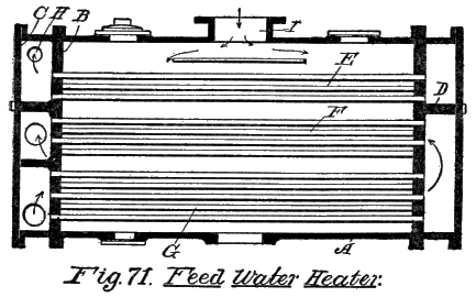
The three sets of pipes, E, F, and G, are so arranged that they carry the water back and forth from one head to the other, and for this purpose the water for cooling the steam enters the port H at one end, passes through the upper set of pipes E to the other end, then back through the same set of pipes on the other side of a partition, not shown, and back and forth through the two lower sets of pipes F, G.
The steam enters at the port I at the top of the shell, and passes down, as it is condensed, being discharged at the outlet J.
CHAPTER X
VALVES AND VALVE FITTINGS
In the use of steam, compressed gas, or any medium which must have a controllable flow, valves are a necessary element; and the important point is to know what is best adapted for the use which is required in each case.
For this reason one of the best guides is to fully understand the construction of each. The following illustrations and descriptions will give a good idea of the various types in use.
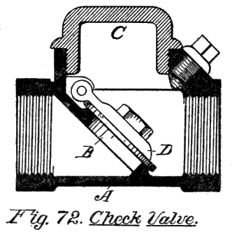
Check Valve.—Fig. 72 shows a longitudinal section of a check valve, which is designed to prevent the water from returning or backing up from the pressure side. The cylindrical body A is threaded at each end, and has an inclined partition B therein which has a circular aperture.
The upper side of the shell has an opening, adapted to be closed by a cap C, large enough to insert the valve D, which is hinged to the upper side of the partition. Water or gas is forced in through the valve in the direction of the arrow, and the hinged valve is always in position to close the opening in the partition.
In case the valve should leak it may be readily ground by taking the small plug E from the opening, and with a screw driver, turning the valve, and thereby fit it snugly on its seat.
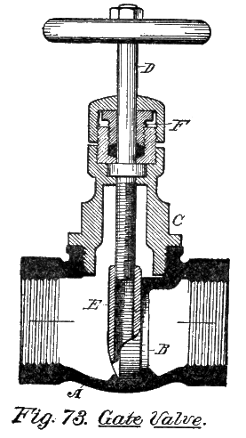
Gate Valve.—The cylindrical shell A has its ends internally threaded, and is provided, midway between its ends, with a partition wall B, having a central aperture. The upper side of the shell has an opening to receive the bonnet C, through which the valve stem D passes. This stem carries at its lower end a gate E which rests against the partition B.
The stem D is threaded to screw into the threaded bore of the gate. A packing gland F surrounds the stem D. It will thus be seen that the turning of the stem D draws the gate up or down, and thus effects an opening, which provides a direct passage for the water through the valve body.
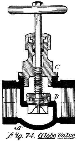
Globe Valve.—A globe valve has the advantage that the valve is forced against its seat by the pressure of the wheel, differing from the gate valve, that depends on the pressure of the fluid to keep it tight.
The valve body A has therein a Z-shaped partition B, the intermediate, horizontally-disposed limb of the partition being directly below the opening through the body, which is designed to receive the bonnet C.
The bonnet has a central vertical bore, the lower end of which is threaded to receive the wheel spindle. The lower end of the spindle carries the circular valve, which is seated in the opening of the Z-shaped partition.
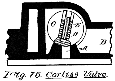
The Corliss Valve.—The valve itself is of the rotary type, as shown in Fig. 75, in which the port A goes to the cylinder, and B is the passage for the steam from the boiler. The cylindrical valve body C has within the aperture B a gate D, one edge of which rests against the abutment through which the port A is formed, and this gate has within it the bar E which is connected with the crank outside of the casing.
The Corliss Valve-Operating Mechanism.—As the operation of the valves in the Corliss type of engine is so radically different from the ordinary reciprocation engine, a side view of the valve grouping and its connecting mechanism are shown in Fig. 76.
The cylinder has an inlet valve A at each end, and an outlet valve B at each end for the discharge of the steam. C is a valve rod from the eccentric which operates the valves, and D a wrist plate, having an oscillatory or rocking motion around its center E. The attachments F F, of the steam rods, open the inlet ports A A, and G G, are the attachments of exhaust rods which open and close the exhaust valves B B. H H are catches which can be unhooked from the stems of the valves A by the governor rods J J.
The vertical links K, K are connected at their lower ends with the pistons of dash pots, and have their upper ends attached to the valve spindles, and act to close the valves A A when the catches H are released by the governor rods J by means of the weights of the pistons in the dash pots.
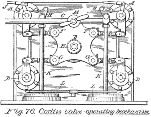
The dash pots L L act in such a manner as to cushion the descent of the links K and thus prevent undue shock. M is a wrist plate pin by which the valve rod C can be released from the wrist plate.
The whole purpose of the mechanism is to provide a means for closing the valves which are at the steam inlet ports, by a sudden action. The exhaust valves, on the other hand, are not so tripped but are connected directly with the wrist plate which drives all four of the valves.
The wrist plate or spider has a rocking motion, being driven by an eccentric rod from the engine-shaft. The mechanism thus described gives a variable admission as the load varies, but a constant release of the exhaust and a constant compression to act as a cushion.
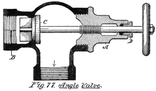
It gives a high initial pressure in the cylinder, and a sharp cut off, hence it is found to be very efficient.
Angle Valve.—One of the most useful is the angle valve, which is designed to take the place of an angle bend or knee in the line of the piping. The mechanism is the same as in the well known globe valve construction, the bonnet A being on a line with one of the right-angled limbs of the body.
The pressure of the fluid should always be on the lower side of the valve C, coming from the direction of the arrow B, for the reason that should the steam pressure be constant on the other side, it would be difficult to repack the gland D without cutting off the steam from the pipe line.
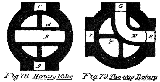
Referring back to the illustration of the globe valve, it will be noticed that the same thing, so far as it pertains to the direction of the steam, applies in that construction, and a common mistake is to permit the pressure of the steam to be exerted so that it is constantly acting against the packing of the spindle.
Rotary Valves.—Two forms of rotary valves are shown, one as illustrated in Fig. 78, where the rotating part, or plug, A has one straight-way opening B, which coincides with two oppositely-projecting ports C, D.
The other form, Fig. 79, has an L-shaped opening E through the rotating plug F, and the casing, in which the plug is mounted has three ports, one, G, being the inlet, and the other two H, I, at right angles for the discharge of the fluid.
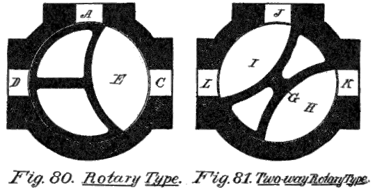
Rotable Engine Valves.—So many different forms of the rotable valve have been made, that it is impossible to give more than a type of each. For engine purposes the plugs are usually rotated in unison with the engine shaft, and a single delivery valve of this kind is shown in Fig. 80.
This has three ports in the casing, namely the inlet port A, and two outlet ports C, D. The plug has a curved cut out channel E, and this extends around the plug a distance equal to nearly one-half of the circumference, so that the steam will be diverted into, say, B, for a period equal to one-quarter turn of the plug, and then into port C, for the same length of time.
Fig. 81 shows a valve which has a double action. The plug G has two oppositely-disposed curved channels, H, I, and the casing has a single inlet port J, and two oppositely-disposed outlet ports K, L.
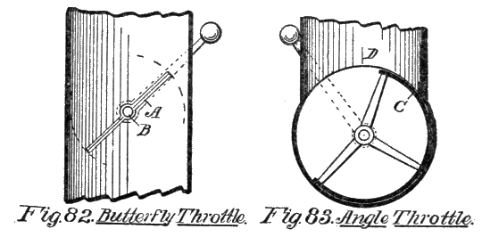
When the plug turns the port L serves to convey the live steam to the engine, while the other port K at the same time acts as the exhaust, and this condition is alternately reversed so that L acts as the discharge port.
Throttle Valves.—The throttle valves here illustrated are those used in connection with gasoline engines. The best known is the Butterfly valve, shown in Fig. 82, and this is also used as a damper, for regulating the draft in furnaces and stoves.
This type is made in two forms, one in which the two wings of the valve are made to swing up or down in unison, and the other, as illustrated, where the disk A is in one piece, and turns with the spindle B to which it is fixed.
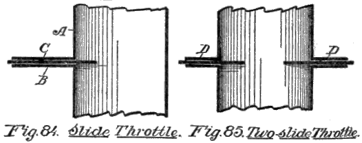
In Fig. 83 the wing C is curved, so that by swinging it around the circle, the opening of the discharge pipe D is opened or closed.
Another design of throttle is represented in Fig. 84. One side of the pipe A has a lateral extension B, which is double, so as to receive therein a sliding plate C, which is easily controllable from the outside.
Fig. 85 shows a form of double sliding plate, where the double lateral extensions project out in opposite directions, as at D, D, and within these extensions are sliding plates which are secured together in such a way that as one is pushed in the other also moves in, and thus acts in unison to close or to open the space between them. It is the most perfect form of throttle valve, as it causes the gases to open directly into the center of the outgoing pipe.
Blow-off Valves.—The illustration shows a type of valve which is used on steamboats and very largely on farm boilers throughout the country. The pipe A from the boiler has cast therewith, or otherwise attached, a collar B, which has a standard C projecting upwardly at one side, to the upper end of which is hinged a horizontal lever D, which has a weight at its other end.
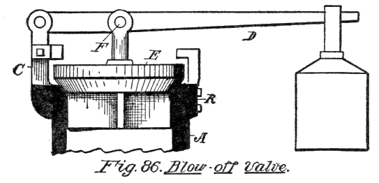
The upper end of the pipe has a conically-ground seat, to receive a conical valve E, the stem of which is hinged, as at F, to the level. The weight may be adjusted to the pressure desired before blowing out and the only feature in this type of valve is the character of the valve seat, which is liable, through rust, and other causes, to leak.
Pop, or Safety Valve.—As it has been found more desirable and practical to use a form of valve which is not liable to deterioration, and also to so arrange it that it may be manually opened, the Safety Pop valve was devised.
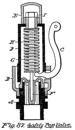
This is shown in Fig. 87, in which the valve seat base A, which is attached to the top of the boiler, has a cup-shaped outlet B, that is screwed to it, and this carries a lever C, by means of which the valve may be manually opened.
A vertical shell D is attached to the cup-shaped portion, and this has a removable cap E. The valve F is seated within a socket in the base, and has a disk head, to receive the lower end of a coiled spring G.
The spring is supported in position by a stem H which extends down from the head, and an adjusting nut I serves to regulate the pressure desired before the steam in the boiler can act.
CHAPTER XI
CAMS AND ECCENTRICS
More or less confusion arises from the terms cams and eccentrics. A cam is a wheel which may be either regular in shape, like a heart-wheel, or irregular, like a wiper-wheel.
The object in all forms of cams is to change motion from a regular into an irregular, or reversely, and the motion may be accelerated or retarded at certain points, or inverted into an intermittent or reciprocating movement, dependent on the shape of the cam.
A cam may be in the shape of a slotted or grooved plate, like the needle bar of a sewing machine, where a crank pin works in the slot, and this transmits an irregular vertical movement to the needle.
A cam may have its edge provided with teeth, which engage with the teeth of the engaging wheel, and thus impart, not only an irregular motion but also a turning movement, such forms being largely used to give a quickly rising or falling motion.
What are called wiper-wheels are designed to give an abrupt motion and such types are used in trip hammers, and to operate stamp mills. In harvesters, printing presses, sewing machines, and mechanism of that type, the cam is used in a variety of forms, some of them very ingenious and complicated.
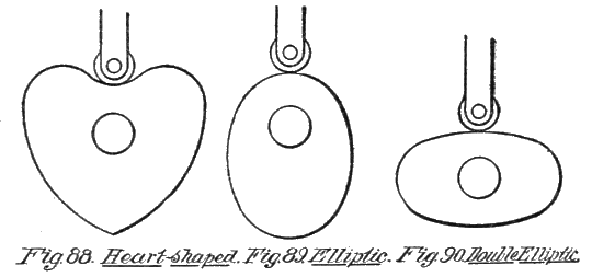
Cams are also used for cutting machines, or in tracing apparatus where it would be impossible to use ordinary mechanism. All such forms are special, requiring care and study to make their movements co-relate with the other parts of the mechanism that they are connected up with.
Simple Cams.—Fig. 88 shows a form of the most simple character, used, with some modifications, to a larger extent than any other. It is called the heart-shaped cam, and is the regular type.
Fig. 89 is an elliptical cam, which is also regular. What is meant by regular is a form that is the same in each half portion of its rotation.
Fig. 90 is a double elliptic, which gives a regular movement double the number of times of that produced by the preceding figure, and the differences between the measurements across the major and minor axes may vary, relatively, to any extent.