Chapter XII · GASEOUS AND LIQUID FUELS (continued 2)
Reading edition
Chemically considered, acetylene is C2H2; it is composed of carbon and hydrogen and belongs to a class of compounds known as hydrocarbons, represented in nature by petroleum, natural gas, etc. It is composed of 92.3 per cent. carbon and 7.7 per cent. of hydrogen, both combustible gases. It is a non-poisonous, colorless gas, with a persistent and penetrating odor. Its presence in the air, to the extent of 1 part in 1000 is distinctly perceptible. When burning brightly in a jet, there is no perceptible odor. When completely burned it requires for its combustion 2½ times its volume of oxygen.
All combustible gases, when mixed with air and ignited, produce more or less violent explosions. Acetylene is no exception to the rule, and when allowed to escape into any enclosed space it will quickly produce a violently explosive mixture, so that it is always dangerous to enter a room or basement with a lamp or flame of any kind where the odor of gas is perceptible. This is quite true with a combustible gas of any kind, but with acetylene all mixtures from 3 to 30 per cent. are capable of being exploded with greater or less violence.
The kindling point of acetylene is lower than coal gas or gasoline gas. To ignite either of the latter gases, a flame is necessary to start the combustion, but a spark or a glowing cigar is sufficient to ignite acetylene. It should therefore be borne in mind that acetylene is not only explosive when mixed with air but that it is very easy to ignite. Under ordinary pressures pure acetylene is not explosive, but at pressure above 15 pounds to the square inch explosions sometimes occur where proper precautions are not observed. At all pressures such as are required for household purposes acetylene is as safe for use as any other gas.
Although acetylene is in danger of exploding when under pressure, it is perfectly safe, when the proper conditions are observed, in tanks for a great many kinds of portable lights.
Where acetylene is used in portable tanks under pressure, advantage is taken of its solubility in acetone. This is a product of the distillation of wood which possesses the property of absorbing acetylene to a remarkable degree. In addition to this property is the more important one of rendering the acetylene non-explosive when under pressure. The tanks for its storage are filled with asbestos or other absorbent material that is saturated with acetone. The acetylene is then forced into the tanks under pressure and is absorbed by the acetone. The safety of this means of storage lies in the degree of perfection to which the tanks are filled with the absorbent material. There must be no space anywhere in the tank where undissolved acetylene can exist. Its freedom from danger under such conditions has been thoroughly demonstrated in its use for railroad and automobile lamps.
The use of acetylene as a fuel for cooking and for the various other purposes of domestic use is successfully accomplished in burners that give the blue flame desired for such purposes. Complete cooking ranges and various other heating and cooking devices are regularly sold by dealers in heating appliances, while water-heaters, hot-plates, chafing-dish heaters, etc., are as much a possibility as with any other of gaseous fuel and in as reasonably an inexpensive way.
Coal gas, containing as it does sufficient carbon monoxide to render it poisonous, will cause death when inhaled for any length of time, but acetylene under the same conditions will have no deleterious effect.
Types of Acetylene Generators.
—There are two general methods of generating acetylene for domestic illuminating and heating purposes: that of adding carbide to water, and that in which the water is mixed with carbide. The two types are illustrated in the diagrams shown in Figs. 209 and 210. The first method, that in which the carbide is dropped into water, is shown in Fig. 209. The tank A is the generator and B is the receiver or gas-holder. The tank A holds a considerable quantity of water and is provided with a container C for holding the supply of carbide. The tank A is connected with the gas-holders by a pipe which extends above the water line in the tank B, where the gas is allowed to collect in the gas-holder G. A charge of carbide, sufficient to fill the holder with gas, is pushed into the tank A by raising the lever H. Immediately the water begins to combine with the carbide and the bubbles of gas pass up through the water and are conducted into the tank B. The holder G is lifted by the gas and its weight furnishes the pressure necessary to force the gas into the pipes, which conduct it to the burners. If this machine were provided with the proper mechanism to feed into the generator a supply of carbide whenever the gas in the holder is exhausted, the machine would represent the modern “carbide to water” generator.
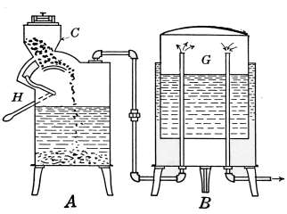
Fig. 209.—Diagram of a carbide-to-water acetylene-gas generator.
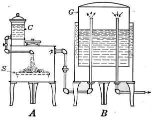
Fig. 210.—Diagram of a water-to-carbide acetylene-gas machine.
The “water to carbide” generator is shown diagrammatically in Fig. 210. As in the other figure, A is the generator and B is the gas-holder. A supply of carbide S is placed in the generator and water from a tank C is allowed to drip or spray onto the carbide. The gas collects in the gas-holder as before. This apparatus represents in principle the parts of a machine for generating acetylene by this process. The actual machines are arranged to perform the functions necessary to make the machines automatic in their action.
Whatever the type of the machine, the object is to keep in the holders a sufficient amount of gas with which to supply the demand made on the plant. Machines representing each of the types described are to be obtained, but the greater number of those manufactured are of the “carbide to water” form.
In the formative period of acetylene generators many accidents of serious consequence resulted from imperfect mechanism. Imperfections have been gradually eliminated until the machines which have survived are efficient in action and mechanically free from dangerous eccentricities.
The qualities demanded of a good generator are: There must be no possibility of an explosive mixture in any of the parts; it must insure a cool generation of gas; it must be well-constructed and simple to operate; it should create no pressure above a few ounces; it should be provided with an indicator to show how low the charge of carbide has become in order that it may be recharged in due season, and it must use up the carbide completely.
Because of the fact that the greater number of acetylene-gas machines of today are of the “carbide to water” type, in the description to follow that type of machine is used. They are generally made in two parts, one part containing the generating apparatus and the other acting as gasometer (gas-holder), but some machines are made in which one cell contains both the generator and gasometer.
In Fig. 211 is shown a two-part, gravity-fed machine, in which all of the internal working parts are exposed to view. The tank (a), as in the diagram, is the generator and the tank (b) contains the gasometer marked G. Each tank possesses a number of appliances which are necessary to make the machine automatic in its action. The part C of the generator contains the supply of carbide, broken into small pieces, a portion of which is dropped into the water whenever additional gas is required. The feed mechanism F is controlled by the gasometer bell G, which is buoyed up by the gas it contains. When the supply of gas becomes low, the descending bell carries with it the end of the lever F, which is attached to the feed valve; this motion raises the feed valve and allows some of the carbide to fall into the water. The gas that is immediately generated passes into the gasometer through the pipe P, and as the bell is raised by the accumulating gas the valve V is closed.
The gas as it enters the gasometer passes through a hollow device W, that looks like an inverted T, the lower edge of which is tooth-shaped and extends below the surface of the water. The gas, in passing this irregular surface, is broken up and comes through the water in little bubbles, in order that it may be washed clean of dust. This device also prevents the return of the gas to the generator tank during the process of charging.
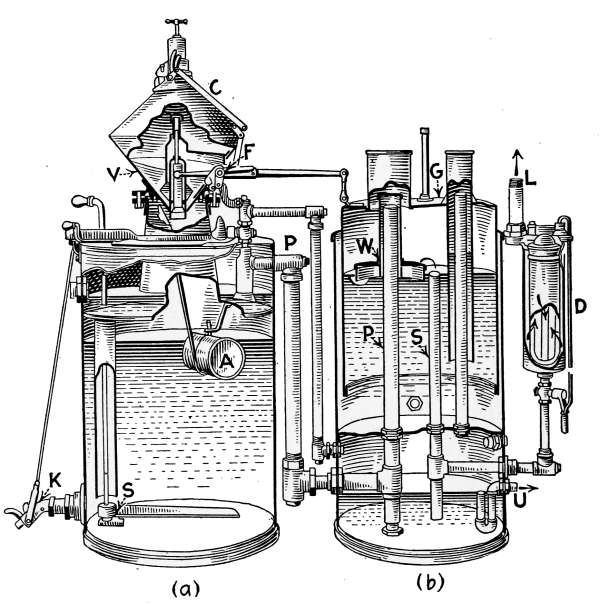
Fig. 211.—Sectional view of the Colt acetylene-gas machine.
The gas escapes from the bell through the pipe S to the filter D, where any dust that may have escaped the washing process is removed by a felt filter. It finally leaves the machine by the pipe L, at which point it enters the system through which it is conveyed to the different lighting fixtures.
It will be noticed that the tank (b) is divided into two compartments, the upper portion containing the water in which the gasometer floats. The lower compartment is also partly filled with water which acts as a safety valve to prevent any escape of gas into the room in which the generator is located. The lower end of the pipes P and S are immersed in the water at the bottom chamber of the tank, from which the gas could escape in case too much is generated and finally exit through the vent pipe U to the outside air.
The float A in the tank (a) is a safety device that prevents the introduction of carbide unless the tank contains a full supply of water. The float is a hollow metal cylinder connected by a rod to a hinged cup under the bottom opening of the carbide holder. When the water is withdrawn from the generator, the float falls and the cup shuts off the carbide outlet.
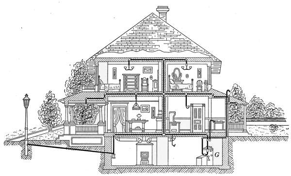
Fig. 212.—Sectional view of a house equipped with acetylene lights and domestic heating apparatus.
The accumulation of lime, from the disintegrated carbide, requires occasional removal from the tank (a); the valve K is provided for this purpose. The lever S is used to stir up the lime which is deposited on the bottom of the tank, that it may be carried out with the discharged water.
Machines of this kind that are safeguarded against leakage of gas or the possibility of accumulated pressure are practically free from danger in the use of acetylene. The accidental leakage of gas from defective pipes and fixtures produce only the element of risk that is assumed with the use of any other form of gas for illuminating purposes.
Acetylene is distributed through the house in pipes in the same manner as for ordinary illuminating gas. The sizes of the pipes to suit the varying conditions of use are regulated by rules provided by the National Board of Fire Underwriters. These rules state definitely the sizes of pipes required for machines of different capacities. Rules of this kind and others that specify all matters relating to the use of acetylene may be obtained from any fire insurance agent.
The general plan of piping is shown in Fig. 212. The generator G is in this case a “water to carbide” machine and is shown connected to the kitchen range, as well as the pipe system which may be traced to the lamps in the different rooms, to the porch lights and to the boulevard lamp in front of the building.
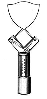
Fig. 213.—Acetylene gas burner.
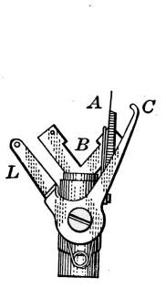
Fig. 214.—Electric igniter for acetylene gas burners.
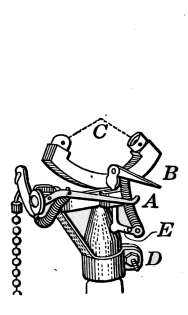
Fig. 215.—Electric igniter for acetylene gas burners.
The type of burner used in acetylene lamps is shown in Fig. 213. The gas issues from two openings to form the jet as it appears in the engraving. These burners are made in sizes to consume ¼, ½, ¾, and 1 foot per hour depending on the amount of light demanded.
Gas Lighters.
—The acetylene gas jets are lighted ordinarily with a match or taper but electric igniters are often used for that purpose. Electric lighters for acetylene lamps are practically the same as those used with ordinary gas lamps but they must be adapted to the type of burner on which they are used. Electric igniters that are intended to be used with lamps placed in inaccessible places are different in construction from those within reach. In Figs. 214 and 215 are illustrated two forms of igniters that are intended to be used on bracket or pendent lamps. They differ in mechanical construction to suit two different conditions. Fig. 214 is an igniter in which is also included the gas-cock. The gas is lighted by pulling a cord or chain attached to the lever L. The movement of this lever turns on the gas and at the same time brings the piece C in contact with the wire A to complete an electric circuit. As the contact between these two pieces is broken, a spark is formed that ignites the gas escaping from the burner at B. On releasing the lever a spring returns the piece C to its original position. The light is extinguished by a second pull of the lever.
Fig. 215 illustrates a style of igniter which may be attached to an ordinary gas-cock. It is attached to the stem of the burner by a clamp D. The gas is turned on by the usual gas-cock and by pulling the chain at the left the jet is lighted. In pulling the chain the arm A is raised and carries with it the arm B. When the arms A and B touch, an electric circuit is formed with a battery and spark coil. When the desired position of the arms is reached, the points separate to form an electric flash which lights the gas.
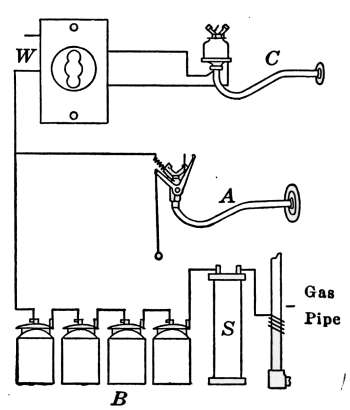
Fig. 216.—Diagram of electric igniters attached to gas burners.
Fig. 216 illustrates in A the method of installing electric igniters like those described. A battery B and a spark coil S are joined in circuit as shown. The gas pipe acts as one of the wires of the circuit. A battery of four dry cells is commonly used for the purpose. The spark coil is a simple coil of wire wound on a heavy iron core, which serves to intensify the spark when the circuit is broken. In using the igniter, it is only necessary to see that the cells are joined in series with the coil and attached to the insulated part of the igniter. As already explained the action of the igniter is to close the circuit and immediately break the contact at a point where the spark will ignite the gas. On being released the igniter returns to its original position.
In the fixture shown at C is an igniter such as is used in places that cannot be conveniently reached. To light the jet, the circuit is completed by turning the switch at W. As soon as the gas is lighted the switch is again turned to break the igniter-circuit. In this device the current passes through a magnet coil in the igniter which acts to open and close the circuit with the same effect as in the others.
Acetylene Stoves.
—Stoves in which acetylene is used as a fuel are quite similar in construction to those which burn coal gas. The principle of operation is that of mixing the acetylene with air in proper proportion so as to produce complete combustion when burned.