Part 9 — CHAPTER II
Reading edition
MILITARY SKETCHING
(While this chapter presents the principal features of military sketching in a simple, clear manner, attention is invited to the fact that the only way that any one who has never done any sketching can follow properly the statements made, is to do so with the instruments and the sketching material mentioned at hand. In fact, the only way to learn how to sketch is to sketch.)
1878. A military sketch is a rough map showing the features of the ground that are of military value.
Military sketching is the art of making such a military sketch.
Military sketches are of three kinds:
Position sketches, Fig. 1;
Outpost sketches;
Road sketches.
All kinds of military sketches are intended to give a military commander detailed information of the ground to be operated over, when this is not given by the existing maps, or when there are no maps of the area.
The general methods of sketching are:
(1) The location of points by intersection.
(2) The location of points by resection.
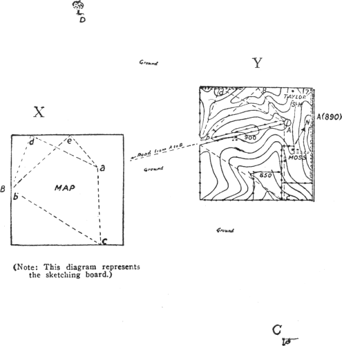
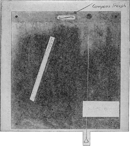
1879. Location of points by intersection. To locate a point by intersection proceed as follows: Set up, level and orient the sketching board (Par. 1872), at A, Fig. 1. The board is said to be oriented when the needle is parallel to the sides of the compass trough of the drawing board, Fig 2. (At every station the needle must have this position, so that every line on the sketch will be parallel to the corresponding line or direction on the ground.) Assume a point (A) on the paper, Fig. 1 Y, in such a position that the ground to be sketched will fall on the sheet. Lay the ruler on the board and point it to the desired point (C), all the while keeping the edge of the ruler on the point (A), Fig. 1 Y. Draw an indefinite line along the edge. Now move to (B), Fig. 1 X, plotted on the map in (b), Fig. 1 X, and having set up, leveled and oriented as at (A), Fig. 1 Y, sight toward (C) as before. The intersection (crossing) of the two lines locates (C) on the sketch at (c), Fig. 1 X.
Fig. 1
1880. Locating points by resection. A sketcher at an unknown point may locate himself from two visible known points by setting up and orienting his sketching board. He then places his alidade (ruler) so that it points at one of the known points, keeping the edge of the alidade touching the corresponding point on the sketch. He then draws a ray (line) from the point toward his eye. He repeats the performance with the other visible known point and its location on the map. The point where the rays intersect is his location. This method is called resection. However, local attractions for the compass greatly affect this method.
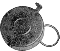
1881. The location of points by traversing. To locate a point by traversing is done as follows: With the board set up, leveled and oriented at A, Fig. 1 Y, as above, draw a line in the direction of the desired point B, Fig. 1 X, and then move to B, counting strides, keeping record of them with a tally register, Fig. 3, if one is available. Set up the board at B, Fig. 1 X, and orient it by laying the ruler along the line (a)-(b), Fig. 1 X, and moving the board until the ruler is directed toward A, Fig. 1 Y, on the ground; or else orient by the needle as at A. With the scale of the sketcher's strides on the ruler, lay off the number of strides found from A, Fig. 1 Y, to B, Fig. 1 X, and mark the point (b), Fig. 1 X. Other points, such as C, D, etc., would be located in the same way.
1882. The determination of the heights of hills, shapes of the ground, etc., by contours. To draw in contours on a sketch, the following steps are necessary:
Fig. 2
(a) From the known or assumed elevation of a located station as A, Fig. 1 Y, (elevation 890), the elevations of all hill tops, stream junctures, stream sources, etc, are determined.
(b) Having found the elevations of these critical points the contours are put in by spacing them so as to show the slope of the ground along each line such as (a)-(b), (a)-(c), etc., Fig. 1 Y, as these slopes actually are on the ground.
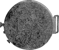
(Tally Register)—Fig. 3 (Clinometer)—Fig. 4
To find the elevation of any point, say C (shown on sketch as c), proceed as follows:
Read the vertical angle with slope board, Fig. 2, or with a clinometer, Fig. 4. Suppose this is found to be 2 degrees; lay the scale of M. D.[22] (ruler, Fig. 2) along (a)-(c), Fig. 1 Y, and note the number of divisions of -2 degrees (minus 2°) between (a) and (c). Suppose there are found to be 51/2 divisions; then, since each division is 10 feet, the total height of A above C is 55 feet (51/2 × 10). C is therefore 835 ft. elev. which is written at (c), Fig. 1 Y. Now looking at the ground along A-C, suppose you find it to be a very decided concave (hollowed out) slope, nearly flat at the bottom and steep at the top. There are to be placed in this space (a)-(c), Fig. 1 Y, contours 890, 880, 870, 860 and 850, and they would be spaced close at the top and far apart near (c), Fig. 1 Y, to give a true idea of the slope.
The above is the entire principle of contouring in making sketches and if thoroughly learned by careful repetition under different conditions, will enable the student to soon be able to carry the contours with the horizontal locations.
1883. In all maps that are to be contoured some plane, called the datum plane, must be used to which all contours are referred. This plane is usually mean sea level and the contours are numbered from this plane upward, all heights being elevations above mean sea level.
In a particular locality that is to be sketched there is generally some point the elevation of which is known. These points may be bench marks of a survey, elevation of a railroad station above sea level, etc. By using such points as the reference point for contours the proper elevations above sea level will be shown.
In case no point of known elevation is at hand the elevation of some point will have to be assumed and the contours referred to it.
Skill in contouring comes only with practice but by the use of expedients a fairly accurate contoured map can be made. In contouring an area the stream lines and ravines form a framework or skeleton on which the contours are hung more or less like a cobweb. These lines are accurately mapped and their slopes determined and the contours are then sketched in.
If the sketcher desires he may omit determining the slopes of the stream lines and instead determine the elevations of a number of critical points (points where the slope changes) in the area and then draw in the contours remembering that contours bulge downward on slopes and upward on streams lines and ravines.
If time permits both the slopes of the stream lines and the elevation of the critical points may be determined and the resulting sketch will gain in accuracy.
Figs. 5, 6, 7, 8, and 9 show these methods of determining and sketching in contours.
Fig. 5
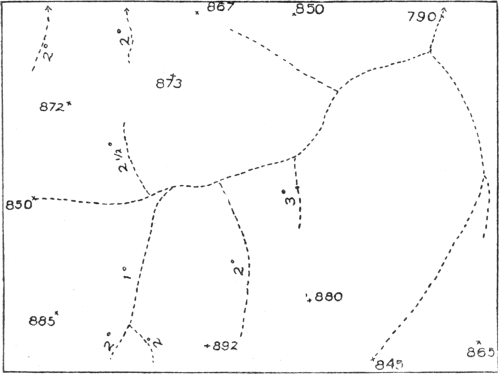
Fig. 6
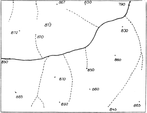
Fig. 7
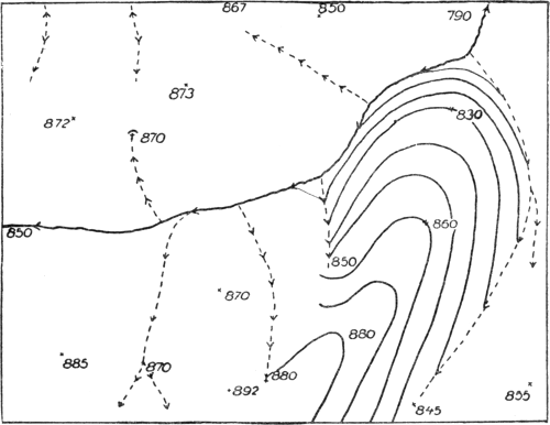
Fig. 8
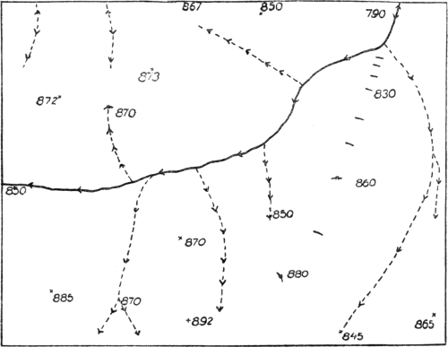
Fig. 9
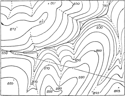
1884. Form lines. It frequently happens that a sketch must be made very hastily and time will not permit of contouring. In this case form lines are used. These lines are exactly like contours except that the elevations and forms of the hills and depressions which they represent are estimated and the sketcher draws the form lines in to indicate the varying forms of the ground as he sees it.
1885. Scales. The Army Regulations prescribe a uniform system of scales and contour intervals for military maps, as follows:
Road sketches and extended positions; scale 3 inches to a mile, vertical (or contour) interval, 20 feet.
Position or outpost sketches; scale 6 inches to a mile, vertical (or contour) interval, 10 feet.
This uniform system is a great help in sketching as a given map distance, Par. 1867a, represents the same degree of slope for both the 3 inch to the mile or the 6 inch to the mile scale. The map distances once learned can be applied to a map of either scale and this is of great value in sketching.
Construction of Working Scales
1886. Working scale. A working scale is a scale used in making a map. It may be a scale for paces or strides or revolutions of a wheel.
1887. Length of pace. The length of a man's pace at a natural walk is about 30 inches, varying somewhat in different men. Each man must determine his own length of pace by walking several times over a known distance. In doing this be sure to take a natural pace. When you know your length of pace you merely count your paces in going over a distance and a simple multiplication of paces by length of pace gives your distance in inches.
In going up and down slopes one's pace varies. On level ground careful pacing will give you distances correct to within 3% or less.
The following tables give length of pace on slopes of 5 degrees to 30 degrees, corresponding to a normal pace on a level of 30.4 inches:
Slopes 0° 5° 10° 15° 20° 25° 30°
Length of step ascending 30.4 27.6 24.4 22.1 19.7 17.8 15.0
Length of step descending 30.4 29.2 28.3 27.6 26.4 23.6 19.7
For the same person, the length of step decreases as he becomes tired. To overcome this, ascertain the length of pace when fresh and when tired and use the first scale in the morning and the latter in the afternoon.
The result of the shortening of the pace due to fatigue or going over a slope, is to make the map larger than it should be for a given scale. This is apparent when we consider that we take more paces in covering a given distance than we would were it on a horizontal plane and we were taking our normal pace.
In going up or down a slope of 3 or 4 we actually walk 5 units, but cover only 4 in a horizontal direction. Therefore, we must make allowance when pacing slopes.
In counting paces count each foot as it strikes. In counting strides count only 1 foot as it strikes. A stride is two paces.
In practice it has been found that the scale of strides is far more satisfactory than a scale of paces.
1888. How to make a scale of paces. Having determined the length of our pace, any one of the following three methods may be used in making a working scale:
1st method. The so-called "One thousand unit rule" method is as follows:
Multiply the R. F. (representative fraction) by the number of inches in the unit of measure multiplied by 1000; the result will be the length of line in inches necessary to show 1000 units.
For example, let us suppose that we desire a graphic scale showing 1000 yards, the scale of the map being 3 inches equal 1 mile:
Multiply 1/21120 (R. F.) by 36 (36 inches in 1 yard, the unit of measure) by 1000,—that is,
(1/21120) × 36 × 1000 = 36000/21120 = 1.7046 inches.
Therefore, a line or graphic scale 1.7 inches in length will represent 1000 yards.
If we desire a working scale of paces at 3 inches to the mile, and we have determined that our pace is 31 inches long, we would have (1/21120) × 31 × 1000 = 31000/21120 = 1.467 inches.
We can now lay off this distance and divide it into ten equal parts, and each will give us a 100-pace division.
2nd method. Lay off 100 yards; ascertain how many of your paces are necessary to cover this distance; multiply R. F. by 7,200,000, and divide by the number of paces you take in going 100 yards. The result will be the length of line in inches which will show 2000 of your paces.
3rd method. Construct a scale of convenient length, about 6 inches, as described in Par. 1863, to read in the units you intend to measure your distance with (your stride, pace, stride of a horse, etc.), to the scale on which you intend to make your sketch.
For example, suppose your stride is 66 inches long (33 inch pace) and you wish to make a sketch on a scale of 3 inches = 1 mile. The R. F. of this scale is 3 inches/1 mile = 3 inches/63360 inches = 1/21120. That is 1 inch on your sketch is to represent 21120 inches on the ground. As you intend to measure your ground distances by counting your strides of 66 inches length, 1 inch on the sketch will represent as many of your strides on the ground as 66 is contained into 21120 = 320 strides. For convenience in sketching you wish to make your scale about 6 inches long. Since 1 inch represents 320 strides, 6 inches will represent 6 × 320 = 1,920 strides. As this is an odd number, difficult to divide into convenient subdivisions of hundreds, fifties, etc., construct your scale to represent 2,000 strides, which will give it a length slightly in excess of 6 inches—6.25. Lay off this length and divide it into ten main divisions of 200 strides each, and subdivide these into 50 stride divisions as explained in Par. 1862.
1889. Position sketching. The following are the instruments used in position sketching:
Drawing board with attached compass (Fig. 2);
Loose ruler, on board (Fig. 2);
Rough tripod or camera tripod;
Scale of M. D.'s (shown on ruler, Fig. 2);
Scale of sketchers, strides or paces (at six inches to one mile), on ruler;
Clinometer (not necessary if board has slope board, Fig. 6);
Scale of hundreds of yards shown on ruler;
Scale of paces.
Methods to be used
(1) Select a base line,—that is, a central line 1/4 to 1/2 mile long in the area to be sketched. It should have at its ends some plainly marked objects, such as telegraph poles, trees, corners of buildings, etc., and from its ends, and intermediate points, a good view of the area should be possible. The base line selected should be capable of being measured.
(2) Set up, level and orient the drawing board at one end of the base (A), Fig. 1, Y, for example. Draw a meridian on the sheet parallel to the position of the magnetic needle. Assume a point (A), Fig. 1, Y, corresponding to the ground point (A), 890, on the sheet, in such a position that the area to be sketched will lie on the sheet.
(3) Sight at hilltops, stream junctures, stream heads, etc., to begin the locations of these points by intersection, labelling each ray so as to be able to identify it later.
(4) Traverse to (b) and complete the locations by intersection as previously explained. If the base line is not accurately measured, the map will be correct within itself in all of its proportions, but its scale will not necessarily be the scale desired.
(5) Draw the details of the country between A and B and in the vicinity of this line, using the conventional signs for roads, houses, etc.
(6) The lines from station (b), Fig. 1, X, to any of the other located points may now be used as a new base line to carry the work over additional area.
(7) In case parts of the area are not visible from a base line, these parts are located by traversing as before explained.
(8) Having learned by several repetitions the above steps, the sketcher will then combine contouring with his horizontal locations.
1890. Outpost sketching. The same instruments are used as in position sketching, and so are the methods the same, except that the sketcher cannot advance beyond the outpost line, toward the supposed position of the enemy. It is often possible to select a measurable base line well in rear of the line of observation,—for instance, along the line of resistance. Secondary base lines may then be taken on or near the line of observation, from the extremities of which additional base lines may be selected, if necessary, and points toward the enemy's position located by intersection. Details are sketched in as in position sketching. For obvious reasons, no traversing should be done along the line of observation.
1891. Road sketching. The following are the instruments used in road sketching:
Drawing board or sketching case;
Loose ruler;
Scale of strides, or paces, if made dismounted; scale of time trotting or walking, if mounted;
Scale of hundreds of yards, at three inches to 1 mile;
Scale of M. D.'s;
Slope board (if clinometer is not available).
Methods to be used
(1) At station 1, Fig. 10, orient the board as described in par. 1872, holding the board in the hands, in front of the body of the sketcher, who faces toward station 2.
Fig. 10
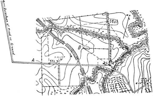
(2) Important points in the vicinity, such as the railroad bridge, the stream juncture, hilltops, are sighted for intersections, lines drawn as shown and the sketcher traverses to station 2.
(3) At station 2 he locates and draws in all details between station 1 and 2, to include about 300 yards on each side of the road.
(4) The traverse is then continued forward as described for 1 and 2.
(5) After some practice of horizontal sketching, as just described, the sketcher will be able to take up contouring in combination. The methods are as described in the paragraph on contouring.
(6) When the traverse runs off the paper as at A, Fig. 10, the following method is followed: Reorient the board so that the road forward will lie across the long dimensions of the paper; draw a meridian parallel to the compass needle and assume a point on the new sheet corresponding to the last point (A) plotted on the first sheet.
(7) On completion of the sketch various sections will be pasted together, so that all the meridians are parallel.
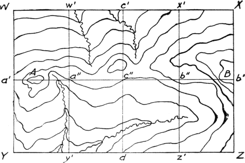
1892. Combined sketching. Let us suppose that we have the rectangle W, X, Y, Z, Fig. 11, assigned to us to map and that we have been given four sketching parties, and that the locations and elevations of A and B have been previously determined by triangulation and are plotted to scale on our rectangle.
A logical step would be to carefully plot the line a' b', and then the lines c' c" and c" d.
If the area is densely wooded we run "line of level" by using the slope board or clinometer and by taking elevations at points arbitrarily selected. Our lines will look something like this:
Fig. 11
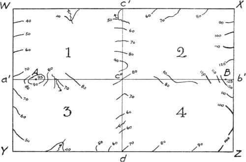
Each party will be given its rectangle with the traverses sketched in. They will each then run similar traverses over the other two sides of their area and then fill in. In this manner the whole work is tied up to the original lines.
Another method
The line A B, Fig. 12, is carefully plotted. Each of the four sketching parties has two sketching groups. One group of party No. 1 traverses line a' Y; then the other group of the party traverses the line a" y'. The first group of party of No. 2 accompanies them. The second group of party No. 2 traverses the line c" d, accompanied by the first group of party No. 3; the second group of party No. 3, and the first group of party No. 4 traverse b" z', and the second group of party No. 4 traverses b' Z. When the first group of party No. 1 arrives at Y, it traverses Y y'. The second group of party No. 1, arriving at y', cuts the sheet along traverse and gives the first group of party No. 2 the part which shows their area; and then traverses toward Y from y'. Upon meeting the first group of party No. 1, they join forces and proceed to fill in their area.
Fig. 12
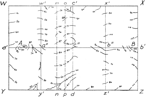
In the same manner areas W X a' b' are filled in.
Fig. 13
The method described above is useful in working over country which is densely wooded, and in which a general view cannot be obtained, for example, in mapping jungles.
An additional article of the sketcher's equipment is a holder for his pencils, alidade, eraser, knife, pins, etc. This consists of a series of small pockets sewed on to a piece of canvas about 7 inches by 4 inches. This can be attached to the left breast of the sketcher's coat or shirt by means of two pins. In addition to keeping all of his implements in a handy place the holder prevents the loss of the several articles. Nothing is so discouraging to the sketcher as to look for his pencil, eraser, knife or even alidade and find that he has left it several hundred yards back where he sat down last to sketch in details. By using the holder the sketcher gets into the habit of replacing articles after they are used and consequently always has them with him when needed. These holders ready made can be obtained from the Secretary, Army Service Schools at Fort Leavenworth, Kansas.
In sketching a good quality of paper should always be used as erasures will be frequent. A specially prepared paper that has the appearance of oiled paper can be obtained commercially and is excellent for sketching in damp weather. It has considerable resistance to rain. Sheets of celluloid prepared for sketching are invaluable in sketching in the rain. These are a part of the equipment of the case of sketching instruments supplied battalions in the regular army. These sheets may be procured at most any dealers.
Points for Beginners to Remember
1893. 1. Always keep your pencils sharpened and have an eraser handy. No one but an expert can sketch with a dull pencil.
2. Use hard pencils when learning to sketch—4H to 6H—and go over your work afterwards with a softer pencil—2H.
3. Do not try to put down on your sketch a mass of small details that are too small to be shown on the scale at which you are sketching. For example, if you are making a sketch on a scale of 3 inches = 1 mile, do not try to show each house in a row of houses; simply indicate that there is a row of houses, by putting down several distinct conventional signs for houses in a row; nor should you try to show every little "cut" through which the road may run. Only use about one sign to the inch of telegraph or telephone lines, for wire fences, etc.
4. When first practicing sketching only plot the route over which you walk, indicating it by a single line. When you can do this with facility, go back over one of these plotted routes and fill in the woods, houses, streams and the other large features.
5. The beginner should sketch the same ground several times over—at least three or four times. Practice alone will make perfect.
6. Always try to compare your finished sketch with an accurate map of the ground, if one is obtainable. Try to practice on ground of which you can obtain a map.
7. Make each course (the distance you go between points where the direction of your route changes) as long as possible.
8. Do not try to contour until you are expert at making a sketch showing all the flat details (roads, streams, woods, houses, etc.).
9. Never try to "sketch in" the contours until you have plotted the stream lines or the direction of the valleys, ravines, etc. The contours are fitted to or sketched around the drainage system; not the drainage system to the contours.
10. Always "size up" ground before you sketch it; that is, take a general view of it, noticing the drainage system (the direction in which the streams flow or ravines run), the prominent hills and ridges, the direction the roads run, etc.
11. Above all things, DON'T FAKE ANY PART OF YOUR MAP.
If the man using your map happens to strike the faked portion, he immediately condemns your whole map as incorrect. Every other part may be highly accurate, but your whole map is discredited because the user strikes the bad part first. You will naturally put little faith in the man who has told you something you know to be untrue. You will always suspect him. So it is with maps. Don't put down anything that you don't know to be correct. If any guess work is to be done, let the man using the map do it,—he knows that he is guessing and will be governed accordingly, but if you do the guessing, he doesn't know where the guessing begins and the accurate work leaves off. Don't fudge. Your name is on the map,—don't have any questionable work hitched up to your name.