Part 2 — CHAPTER XII FIELD-TRIALS IN 1903 (continued 2)
Reading edition
“M. Blériot, whose courage as a sportsman equals his learning as an engineer, was fortunately uninjured. An inspection of the apparatus showed that one blade of the propeller was bent, which was sufficient to prevent the maneuver made by the aviator having its desired effect and contributed to the fall. The engine will be repaired without difficulty and the trials will be resumed Friday.”
On August 10, he made a flight of 80 m., but the motor was not in perfect order, so Blériot did not make other trials. He decided, however, to substitute definitely a 50 HP. motor for the 24 HP. motor with which he made all the experiments above reported, which were of a character to encourage the most sanguine expectations.
Ferber advised Blériot to adopt an elevating rudder also, because the effect produced by changing the position of the center of gravity, although efficacious is very difficult and delicate to control.
The conclusion of an article by Ferber in “Nature” of August 10, is worthy of note. He says: “Let us remark, in conclusion, how fruitful is the method of personal trial which we have always advised in preference to any calculation. This year, with his fourth apparatus, Blériot has not met with any damage to his aeroplane. He made the trials himself and they quickly led to results, because each trial gave him an exact idea of what was to be corrected. That is the condition of success.”
◊
[p285]
APPENDIX STUDY OF THE AMERICAN BUZZARD AND THE “JOHN CROW”
In the preparation of this Memoir, the writer has deemed it best to generally omit any mention of plans and ideas which were brought forth in the work, unless constructions or tests in accordance with them were carried to a sufficient extent to admit of some definite conclusion regarding them. However, owing to the important part played by the warping of the supporting surfaces, or the variation in the angle of auxiliary surfaces, in the methods of preserving the equilibrium of practically all flying machines of the present day, it may be of interest to here add a short mention of the direction in which plans along this line were originally proposed in this work. Mention has already been made of the importance which Mr. Langley attached to the study of the works of the great master-builder, Nature, though recognizing at the same time that owing both to the difference in the forces and methods of construction possible to man, it was not in general possible for him to produce the best results by attempting to too closely imitate the methods or plans of Nature.
Mr. Langley considered it not practicable or best to attempt to imitate the details of construction of the flying mechanism of birds. At the same time, he strongly believed that much was to be learned from them about the practical side of the art of balancing, and he therefore spent a great deal of time both in analyzing the methods practiced by the birds in preserving their equilibrium and in criticizing his own plans in this direction in the light of what Nature would seem likely to do if she had to construct a flying creature on such a large scale. In carrying on his investigations in the art as practiced by the birds, he made a trip to Jamaica during the early weeks of 1900, in order to study the species of buzzard which are so numerous and tame there and are known locally as the “John Crow.” After his return from this trip he wrote the following very interesting letter to Mr. Robert Ridgway, requesting certain data regarding the American buzzard, which he wished to compare with some data on the “John Crow” which he had obtained on this trip:
MARCH 29, 1900.
DEAR MR. RIDGWAY:
I have just returned from Jamaica, where among other occupations, I have been studying the evolutions of the buzzard locally called the “John Crow,” a soaring bird which is almost as much superior in skill to our buzzard as that is to a barn-yard fowl in its power of keeping itself in the air without flapping its wings, in what is very nearly a calm.
I have observed particularly the following points with the Jamaica specimen (which I can only give, however, approximately), and I should like to have you give corresponding ones for our Washington buzzard if you can oblige me. [p286]
I note here that the measurements were made on a live bird and that it was impracticable to get the separate weight of the wings except by estimate, but the two wings may be estimated collectively as 114 lbs., the whole weight being 234 lbs. to 3 lbs.
Approximate values:
Weight of the bird complete, 3 pounds.
Length of bird, 23 inches.
Spread of wings from tip to tip, 5 ft. 5 in.
Complete curtate area of both wings (that is, the area of the shadow of the bird’s wings when these are fully extended under a vertical sun) is 600 square inches, or nearly 4 sq. ft., consequently each square foot of the bird’s sustaining surface carries 34 lbs. Diedral angle nearly 150°.
When the bird is soaring in a nearly calm atmosphere, which it inexplicably does,—soaring I mean nearly in line of the observer’s eyes and coming directly to of going directly away from him,—it presents nearly the following appearance:

FIG. 1—Jamaica, Mch. 22, 1900. “John Crow.” Sketch soaring horizontally, by W. H. Holmes. Weight 3 lbs. Total wings area = 546 in. Perpendicular distance c below a b = 3.3 in. =
√(546)7 = CP2−CG2.
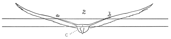
FIG. 2—Another.
CP2−CG2 = 3.3 in. = √(546)7.
FIGS. 1 and 2.—Type sketches of wings by Holmes from a mean of positions taken from his own sketches and photographs, and also from sketches and photographs by Langley.

FIG. 3.—Type sketch of same birds, average type, position of wings.—S. P. Langley.
CP2−CG2 =3.6 in. = √(546)6.5.

FIG. 4.—Average typical position of wings in soaring gull. From memory by S. P. Langley. (The scale here may be taken approximately at 113).
[p287]
I must preface what follows by a little statement of the things which particularly interest me here and which are not a naturalist’s ordinary concern.
First, I want to know the CG of the bird when in flight. You will understand that though there is but one center of gravity (here symbolized as CG), it may be considered (1) with reference to its position on the horizontal plan of the bird with wings extended, when it will always be found somewhere in the medial vertical plane, passing through the body, and usually nearly at a certain point with reference to length, the position thus considered being called CG, or (2) the position of the same CG with reference to a vertical plane passing transversely through the medial line, the position thus considered being called CG2. In the latter case you will understand that the CG which is that of the whole body, wings and all, will be carried more or less upward when the wings are thrown high up, and will be carried temporarily downward when the wings are at their lowest point of the stroke. It would have a certain position when the bird was at rest and another position when it was soaring and the wings were above the body.
The soaring bird is chiefly held upward by the pressure of the air under each wing, and just as the common center of gravity is a point where all the efforts of gravity are supposed to be centered, so there is a common center of pressure, or one point where all the efforts of the upper pressure of the air may be supposed to be centered, and it will be clear, on very little consideration that this latter point must be always nearly in a vertical line through the CG, and usually above it. Call it CP.
CG1 and CP1 are then, the symbols of CG and CP as referred to the horizontal plane. CG2 and CP2 are the symbols for the corresponding ones when referred to their position in the vertical plane.
I shall be glad to explain to you, if you are not familiar with it, the simple method of finding the CG1 and CG2. It consists in bending the wings into just the position that they would ordinarily occupy above the body in plain soaring flight, keeping them there by a very light bent stick or wire, then hanging the bird up by a line attached to the tip of one wing, and see where this line would pass through the body of the bird, for the CG will be somewhere in this line. After marking then, on the body of the bird its position, hang it up a second time by the head or tail and note again where the new vertical line runs in the new position. There is but one CG and but one point in which two straight lines can cross, and that will be the CG necessarily. Note with all care just where this is above or below the center of the body of the bird.
As for the CP for either wing, that may be nearly found by tracing the wing on a flat piece of thick paper or cardboard strong enough not to bend much—cutting out the tracing and balancing it well on the point of a pencil—the point about which it balances is very near CP2 or the center of pressure in the vertical plane. There is such a point of course in each wing, and when they are thrown up in the actual position that they have in calm soaring flight, we may suppose a horizontal line drawn between them, and it is the distance from this horizontal line to CG2 compared with the area of the wings or with the distance between their extended tips which we want to know, which gives the vertical distance which the CG is below the CP, the thing we want to know.
It will be very convenient also to have a wing dissected from the body and the wing itself held in about the soaring curve by a bit of light stick balanced on a pencil point, which will give the CG of the wing as distinct from that of the body. However, the three things I principally want, beside a sketch or [p288] photograph of the bird from about its own level coming directly toward or going directly away in soaring flight, are these:
Approximate weight of the bird,—and approximate tracing of its extended wing with the area, so that we can tell the area of the supporting surface relative to the weight, and finally, the distance between CP2, and CG2, which is obtainable by the process which I have explained.
I am afraid that what I have just been describing at such length may have a certain obscurity to you, but if you will give me an opportunity, I shall be pleased to illustrate it with the actual experiment when the bird is hung up by a string, and you will see that it is in reality simple.
Referring to the sketches on page 3 of this communication, a and b correspond to the centers of pressure on either wing where the upward pressure of the air distributed over each wing may be supposed to be gathered in a single point. This, as I have said, is called the center of pressure with reference to the vertical flight, and its symbol is CP2, while the horizontal dotted line between them represents the level of CP2, from the best estimate that I could make when the wings are in their natural position of soaring. It is evident that this line passed far above the body of the vulture, and if (the corresponding symbol for the height of the center of gravity being CG2), the CG2, of the entire bird be taken, it will be found to lie nearly in the point c. Where c is in the present case, I could not determine exactly in my hasty examinations in the live bird, but I assume that it is about 12 way between the central horizontal axial line of the bird’s body and the upper portion. I repeat that it is important to me to know what the vertical distance is between CP2 and CG2 in each specimen of soaring bird. I may observe in illustration that in the common sea-gull, it is nearly as shown in the faint sketch; that is to say, that the corresponding line a b in the soaring gull passes distinctly through the upper part of the body, and the distance down to the CG2 of the whole in the gull is almost nil, while in the buzzard it is very considerable as shown by the corresponding distance in the “John Crow.”
Now, what I want to get from you is the corresponding figures for an average specimen of our Washington buzzard. If you will kindly have one killed and weighed while fresh, and before the rigor-mortis has set in, first noting the position of its wings when soaring in a calm, and (if possible) when coming toward you or going away in about a horizontal plane with your eye, in which position the wings will be elevated and bent somewhat as in the case of the above sketch of the “John Crow”; if you will kindly do this, so as to give me corresponding facts with reference to the buzzard, namely weight, area of extended wing surface, distance between tips as bent up in ordinary flight, distance between extended tips, the quantity CP2−CG2, and also will make such a tracing of the buzzard’s wing as Mr. Manly will show you of the “John Crow’s,” I shall be obliged.
My impression is that the buzzard is a considerably heavier bird than the “John Crow,” without, however, very much greater spread of wing. I may observe that when the wings of the Jamaica bird were spread out, they were spread quite to their utmost extent, and the distance between the tips of the terminal feathers was much greater than when in flight. I wish you would kindly also add the scientific name of the “John Crow,” with any particulars that you would think of interest.
If there be any special expenses incurred in the preparation of this memorandum, including the time of a photographer, I will direct them to be paid from the Smithsonian fund. [p289]
If you could get Mr. Holmes (who made most of the sketches and all of the photographs of the “John Crow”), to try and do something like this for your buzzard, especially getting such a photograph of it in flight, as will give the position of its center of gravity relative to the center of pressure on the wings, it would add very greatly to the value of your memoranda, and I think Mr. Holmes takes so full and intelligent an interest in the subject, that he might be pleased to give his help.
Very truly yours,
S. P. LANGLEY,
Secretary.
MR. ROBERT RIDGWAY,
Smithsonian Institution,
Curator, Division of Ornithology, U. S. National Museum, Washington, D. C.
In response to this request, Mr. Ridgway submitted the following very interesting information:
SMITHSONIAN INSTITUTION,
UNITED STATES NATIONAL MUSEUM
WASHINGTON, D. C., October 16, 1900.
PROF. S. P. LANGLEY,
Secretary, Smithsonian Institution.
SIR:
I have the honor of submitting herewith the data obtained by Mr. Rolla P. Currie concerning measurements, etc., of the common Turkey Buzzard (Cathartes aura) of the United States, as requested by you in your letter of March 29, last.
The difficulties in the way of securing these data, already explained by me in previous communications, are responsible for the delay in submitting them.
Hoping that this material may prove of use to you, I am,
Very respectfully,
R. RIDGWAY,
Curator, Division of Birds.
MEMORANDA IN REGARD TO THE TURKEY BUZZARD (SECOND SPECIMEN)
1. Weight.—1850 grammes.
2. Area of outstretched wings.—641 square inches. (Computed from three sheets of tracings, A1 and A2 comprising the entire area of both wings; B, a single wing.)
Note.—As the bird was in process of moult, one of the large wing quills, as shown by the tracings and compo-board patterns, is but partially developed, thus slightly modifying the results obtained. Its length, if full grown, would be nearly the same as that of the quill just above it.
3. Distance between the tips of these wings.—5 feet, 8.7 inches.
4. Distance between the tips of the same wings when the bird is in horizontal soaring flight.—Estimating the dihedral angle of the wings to be 150°, and elevating the wings so as to make this angle, the distance between their tips [p290] measures 5 feet, 5.7 inches, or 3 inches less than when fully extended in the horizontal plane.
5. The position of the center of pressure of the wing.—This is indicated on two compo-board patterns, C and D. C was made from a fully extended wing, while D was made from the wing in the soaring position. The centers of pressure of the wings are about 2 feet, 0.5 inches apart, or 1 foot, 0.25 inches from the central point of the bird’s body.
6. The position of the center of gravity of the soaring bird.—(Length of buzzard, 26 inches.) The center of gravity of the soaring buzzard in the horizontal plane, CG1, was found to lie 912 inches behind the tip of the beak and 1612 inches in front of the tip of the tail.
The center of gravity of the soaring bird in the vertical plane, CG2, was found to lie 2.8 inches above the ventral point of the body and 1.6 inches below the dorsal point, the depth of the bird’s body at CG1, being 4.4 inches.
In determining the center of gravity, the bird was frozen in the soaring position, its wings making a dihedral angle of 150°. It was then hung up, first horizontally and then vertically, and balanced till the line from which it was suspended coincided with a plumb-line placed in front of it; the measurements were then made.
The bird was afterwards, and while still frozen, hung up in the same way in Mr. Smillie’s photographic room, and exposures made by him in both positions. These photographs, E1 and F1 were enlarged to natural size, and measurements made on the enlargements yielded, as nearly as could be determined, the same results as when taken directly upon the bird.
As determined by measurements upon the buzzard in soaring position, the center of gravity was found to be 2.65 inches below the center of pressure (estimating the center of pressure to be at the bend of the wing); or, employing the compo-board pattern in a corresponding position, the distance was seen to be a small fraction of an inch less.
7. The position of the root of the wing.—This is indicated on the tracing A1.
a. (Depth of the body on a vertical line with root, 3.5 inches.) The root lies 1.6 inches below dorsal line, 1.9 inches above ventral line.
b. (Length of body, 26 inches.) The root lies 7.6 inches behind tip of beak, 18.4 inches in front of tip of tail.
8. The dihedral angle between the wings.—The photographs taken previously were not sufficiently large or distinct to enable us to determine this with exactness. It was estimated, however, as 150°, and experiments were made on this basis.
9. The center of gravity of the dissected wing.—This was found, first, for the wing having all the muscles, up to the ball and socket joint, intact. One of the wings was frozen in the soaring position and its center of gravity found by balancing on a point. Its position was marked by a wire thrust through the wing at this place, and the wing (H) is preserved in formalin. This position is also marked on a special tracing, I. It lies 6 inches from the base of the humerus bone (root of wing). Secondly, it was found for the wing denuded of all muscle. Its position was marked on the other wing of the bird, which is preserved dry, spread in the soaring position. It lies 934 inches from the base of the humerus. [p291]
10. The weight of the dissected wing.—
a. With all muscle up to the ball and socket joint intact, 325 grammes.
b. With all muscle removed, 190 grammes.
Weight of muscle, therefore, 135 grammes.
The position of the root of the tail.—
a. In the horizontal plane, 11.8 inches in front of the tip of the longest tail feather; 14.2 inches behind tip of beak.
b. In the vertical plane: (depth of body from ventral point below root of tail to a point directly above, which is on a level with the highest point of the back, 2.5 inches.) 1.5 inches above ventral point, 1 inch below dorsal point.
Weight of tail.—With muscle, 40 grammes; without muscle, 30 grammes. Weight of muscle, therefore, 10 grammes.
EXHIBITS ACCOMPANYING THESE MEMORANDA
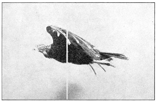
EXHIBIT E1.—Turkey Buzzard suspended in soaring position. (R. P. Currie.)
A1 and A2. Two sheets, comprising a tracing of the entire turkey buzzard with fully outstretched wings. From these the area of the wings and the distance between their tips was obtained. The position of the root of the wing and the root of the tail is also marked on one of these sheets.
B. One sheet, comprising a tracing of a single wing, and from which the area was also computed. This area, multiplied by 2, gives the same result as the sum of both wings on A1 and A2. The compo-board pattern C was made from this tracing.
C. Compo-board pattern of fully extended wing, on which the center of pressure is indicated.
D. Compo-board pattern of wing in soaring position, on which the center of pressure is shown. [p292]
E1. Photograph of bird in soaring position, suspended horizontally.
E2. Same, enlarged to natural size.
F1. Photograph of bird in soaring position, suspended vertically.
F2. Same, enlarged to natural size.
G. Tracing of wing in soaring position, from which the compo-board pattern D was made.
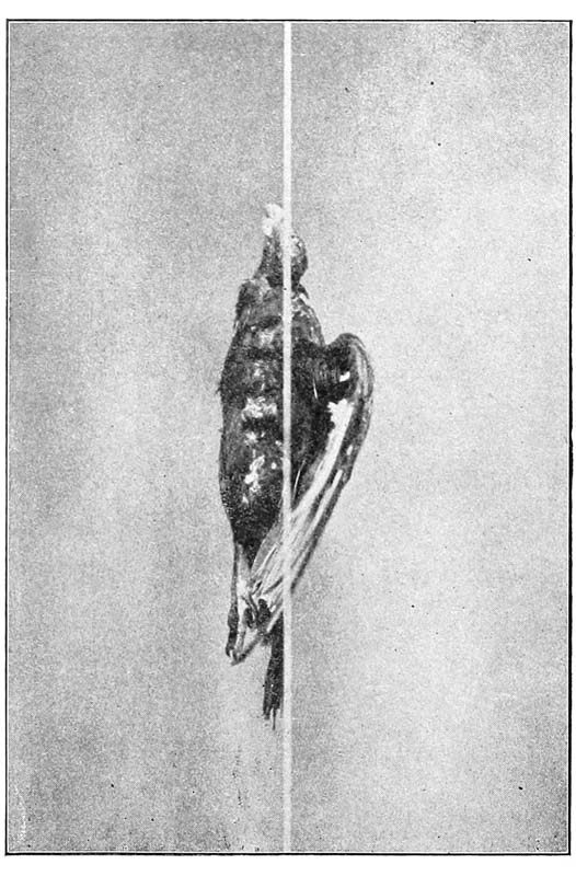
EXHIBIT F1.—Turkey Buzzard suspended vertically in soaring position. (R. P. Currie.)
H. Wing preserved in formalin, on which the center of gravity is recorded.
I. Tracing of wing H when frozen in soaring position, on which the center of gravity is marked.
J. Wing with muscle removed, on which the center of gravity is shown.
Several persons connected with the Smithsonian Institution and U. S. National Museum have contributed towards securing the results herewith submitted. Among them, I desire especially to mention Mr. W. H. Holmes, Mr. [p293] F. A. Lucas, Mr. N. R. Wood, and Mr. R. L. Reed. Mr. Holmes superintended the experiments in connection with No. 6 (finding the bird’s center of gravity), and by his suggestions and criticisms helped me in many other particulars. The photographs and enlargements were made by Mr. T. W. Smillie.
Respectfully submitted,
ROLLA P. CURRIE,
Aid, Division of Insects, acting in the Division of Birds.
OCTOBER 16, 1900.
The feats of airmanship performed by the “John Crow” seemed to greatly impress Mr. Langley and shortly after this trip he wrote the following letter to the writer:
SMITHSONIAN INSTITUTION
WASHINGTON, D. C., April 16, 1900.
DEAR MR. MANLY:
I am reminded of the consequence that I have, in connection with Mr. Chanute and perhaps Mr. Huffaker, attached in the past to the possibility of directing the bird, and consequently the flying machine, by the mere inflection of the wing, that is, by changing its angle; and you recall to me that Mr. Huffaker at one time proposed to arrange a wing, with some provision of a spring, which should enable it to change its angle automatically. . . . .
I have been noting this ability to guide by the slight inflection of the wing, in my studies of the Jamaica buzzard, and am ready to say that I think, while the quarter-sized working model of the great aerodrome is building, it will be worth while to make some arrangement of the frame or wing-holder which will make it possible to test this idea. I will endeavor to work out something of the kind more in detail myself, but whatever it is, it will apparently involve the ability of the wing to rotate about a line passing nearly through it lengthwise, and an allowance for this; if not in the wing itself, then in the wing-holder; will need to be made while the present model is under construction.
I will request you to especially look out for this, as far as you can on these indications.
Very respectfully yours,
S. P. LANGLEY,
Secretary.
The instructions and suggestions contained in this letter and in many conferences on the subject were never carried out by the writer, on account of the extreme pressure of the work already on him which had for its object, not the production of a flying machine which would embody all of the control which we wished it to have, but which would be burdened only with such devices and arrangements as would enable it to transport a human being, and thus demonstrate the practicability of human flight.
[p294]
SECRETARY LANGLEY’S INSTRUCTIONS TO ASSISTANTS
SMITHSONIAN INSTITUTION, WASHINGTON, D. C., November 30, 1895.
DEAR SIR:
The following instructions are to replace those of May 13, 1895:
1. The minimum fraction of its own “flying weight” (that is, weight complete with initial water and fuel), which the aerodrome shall lift on the pendulum, is 50 percent,50 under such engine power as can certainly be gotten up in the field and maintained during forty seconds from the time the aerodrome is let go.
The blast, the pumps, and all other essential parts must, in other words, be in such a condition that steam enough for this lifting over 50 per cent of weight can be gotten up readily and surely in the field and in a time which will still leave at least forty seconds’ supply.
2. The minimum relation of supporting area to weight in any aerodrome constructed hereafter, is to be two feet to the pound,50 and the minimum of power at the rate of one steadily-maintained horse power50 at the brake under ordinary conditions, to not over twenty-two pounds (ten kilos) of flying weight. In absence of a brake determination horse power may be taken—
H. P. =
revs. per min. at rest × pitch × diameter (in ft.) × thrust (in lbs.)
33,000
.
These rules do not apply to No. 5, but they do to No. 6, which is to be built over, if necessary, to meet them.
3. In balancing an aerodrome, unless otherwise instructed, set wings at a root angle of either 10°, 7°, or 5°, after being certain from previous inversion and sanding, that the tip angle in motion will not differ from this root angle as much as 5°.
The object in balancing any aerodrome with a single pair of wings is to be able to bring the c g2 under their c p2 without any reference to the tail, which supports nothing, unless specially ordered. But as this condition cannot now be obtained in Nos. 5 and 6, these at any rate, and perhaps future aerodromes, are to carry a second pair of wings. When this second pair of wings is of nearly equal size with the first it is to be assumed in preliminary adjustments for weight and center of pressure, that the second pair has two-thirds the lifting efficiency per unit area of the first.
Calling the whole distance from the mean center of pressure of the wings to the center of gravity M. M is to have a definite relation to the breadth of [p295] wings from tip to tip (b) and total fore and aft length (1), which is provisionally fixed at M =√(bl)8, and the line of thrust is to be not over one-fourth the way from c p2 to c g2.
Generally speaking the front pair of wings will be fixed in position and the adjustment for balancing made by moving the rear pair.
The individual weights of all parts checked by lump weighing are to be given by the caretaker (Mr. Huffaker), under the general scheme shown in the note. The work on the aerodromes being divided into two classes, viz.: metal work and all which is not metal, the two in charge of this work (Mr. Reed and Mr. Maltby) are severally responsible for knowing the weight in grammes of any of the parts they have put into their work, giving these weights to Mr. Huffaker, together with any data for filling out the annexed tables,51 on his request.
Until further orders, Mr. Huffaker is charged with the responsibility of seeing that these conditions are met before any aerodrome is boxed, and will keep the record of weights of the aerodromes and their principal parts as already completed, in a book, to be preserved in your keeping, which will also be arranged to show with signed photographs and descriptions, and with sketches where needed, the condition and weight (as far as constructed) of every aerodrome, and of any new construction of any part, on the first of each month.
Particular attention is directed to the preceding paragraph, and to the need that evidence of a definite character is to be obtained and preserved of everything already done, and being done.
Without special orders to the contrary, you will not authorize the boxing of any aerodrome which does not, to your knowledge, meet these conditions.
Each aerodrome is to have the following parts in duplicate or in triplicate:
2 pairs wings;
2 pairs tails;
2 pairs light silk covered rudders;
3 pairs wheels;
with any other parts in duplicate or triplicate, which experience has shown to be necessary.
Mr. Reed will not box any aerodrome till a certificate from Mr. Huffaker can be put on the inside cover, with the list of contents, showing what the conditions are as to weight, wing area, power, etc., and the person in the field charged with the duty of launching the aerodrome (at present Mr. Reed), is authorized not to let it go unless he is satisfied that it has a full forty seconds’ supply of steam. [p296]
I am satisfied that a great deal of time is lost in putting the aerodrome together for flight, owing to the absence of any preliminary drill in doing this. Before it goes into the field the whole is to be completely boxed, and then taken out from the box and set up on the clutch, and steam gotten up for flight. All this is to be done in the shop before the final boxing, and provision is to be made so that no wiring or adjusting of parts is to be done in the field which can possibly be avoided by forethought in the shop. The tail-piece, for instance, is to be bushed with brass, so that it will always come into the same place, and make a tight fit, in spite of wetting or shrinking, in the steel tube, where it is to go into a guide-way with a bayonet spring, or a like contrivance for setting it at once securely into position.
The mean positions of the wings and tail are to be laid out in some way permanently on the mid-rod, but every guy-rod or adjustable piece is to be arranged so as to fit at once securely and permanently in its position without wiring or like slow process.
Very truly yours,
S. P. LANGLEY,
Secretary.
W. C. WINLOCK, Esq.,
Assistant in Charge,
Smithsonian Institution.
A copy to be communicated to:——
Mr. Huffaker,
Mr. Reed,
Mr. Maltby.
FOOTNOTES.
◊
[p297]
DATA SHEETS.
DATA SHEET No. 1. Weight of Aerodrome No. 5, as photographed on May 11, 1896. Certified to by R. L. Reed, May 6, 1896.
Parts. Sizes. Weight.
m. ft. gr. lbs.
1 Frame, including everything of metal, permanent and undetachable, such as bed-plate, cross-rods for the support of propellers, bearing points for clutch, etc. 2443
2 Engine, gears, shafts, etc. 1110
3 Pump, pump shaft 231
4 Hull covering 350
5 Gasoline tanks, valves 178
6 Smokestack 342
7 Float 275
8 Reel 77
9 Wing clamps, 235; clamp for guy-posts, 29 264
10 Other things, counter 75
11 Burners 360
12 Boilers 651
13 Separators, steam gauge, pipe to engine 540
14 Exhaust pipe 143
15
16
17 Wings (without clamp) 1950
18 Tail (without clamp)
19 Rudder 350
20 Guy sticks, each, 57 114
21 Propellers 800
22 Extra length of midrod, 308; drop piece for rudder, 40 348
23 Wood Bowsprit 74
24 Other things
25
26
27 Fuel (at starting flight) 200
28 Water (at starting flight) 900
29
30
31 Sundries unknown
32
33
34 Total flying weight 11,775 26
35
36
37
38 Total area of support (not including tail) . . . sq. ft. 68
39 Total area of support in feet, divided by total flying weight in lbs. 2.6
40 Total area of horizontal tail . . . sq. ft.
41 Total area of rudder (vertical) . . . sq. ft. 6
42 Horse-power at brake. Horse-power by formula* .72 7
43 Minimum pressure during 40 secs. lift, 150 lbs.
44 Lift at pendulum (during 40 secs. absolute) 5772
45 Lift at pendulum (during 40 secs. in terms of wt.) 49%
46 Minimum pressure with which wheels turn, 10 lbs.
47 Position of center of pressure of wings† F. W., 1575; R. W., 1383.5
48 Time of getting up full steam, 1 minute
49
50 Curvature of wings, 1/11
51 Root angle of wings, 9°
52 Tip angle of wings, 9°
53 Position of wings, Front rib on F. W., 1607; R. W., 1415.5
54 How guyed
55
56
57
58 Position of tail
59 Angle of tail
60 Co-efficient elasticity of tail
61 Position of rudder, center, 1288.3; rear end, 1229.8
62 Line of thrust, 2500
63 Line of thrust, 1500 which is 9 cm. below the center of midrod
64 Center of gravity1 of whole, 1497
65 Center of gravity2 2501, i. e., 1 cm. above line of thrust
66 Center of pressure1 of whole estimate, 1498
67 Center of pressure2, 2536
68
69
70
71
72
Parts. Remarks.
1 Front end of bowsprit, 1686.3.
2 Front end of midrod, 1611.6.
5 Front edge of F. W., 1607.
8 C. of P. on F. W., 1575.
11 Back edge of F. W., 1527.
14 Back edge of cross frame, 1509.
17 Line through center of propellers, 1500.
21 C. of G., 1497.
24 Front edge of R. W., 1415.5.
27 C. of P. on R. W., 1383.5.
30 End of mid-rod, 1360.5.
33 Front end of rudder, 1343.8.
36 Back edge of R. W., 1335.5.
39 Center of rudder, 1288.3.
41 Back end of rudder, 1229.8.
Footnotes.
* H. P. = (Rev. × diam. × pitch ratio × thrust)/33000
† This is calculated on the assumption that the center of pressure on each wing or on pair of wings at a motion of 2000 feet per minute is in ordinary curved wings 2-5 the way from front to rear, that for wings of usual size the rear wings have 2-3 of the efficiency per surface of the front ones and that the tail proper bears no part of the weight; but if rear wing is smaller or larger this efficiency is smaller or larger per unit of surface.
[p298]
DATA SHEET No. 2. Weight of Aerodrome No. 6. Certified to by R. L. Reed, November 27 and 28, 1896.
Parts. Sizes. Weight.
m. ft. gr. lbs.
1 Frame, including everything of metal, permanent and undetachable, such as bed-plate, cross-rods for the support of propellers, bearing points for clutch, etc. 1178
2 Engine, gears, shafts, etc. 1043
3 Pump, pump shaft 190
4 Hull covering 345
5 Gasoline tanks, valves 306
6 Smokestack, 302; burner, 172 474
7 Float 275
8 Reel 77
9 Wing clamps, 238; drop piece for rudder, 40 278
10 Other things 156
11 Boiler, frames, mica cover 694
12 Separator, steam gauge, pipe to engines 535
13 Exhaust pipe 82
14
15
16
17 Wings (without clamp), wet 2154
18 Tail (without clamp)
19 Rudder 375
20 Guy sticks, each 53 106
21 Propellers 644
22 Extra length of midrod 398
23 Wood bowsprit 135
24 Counter 75
25
26
27 Fuel (at starting flight) 250
28 Water (at starting flight) 2350
29
30
31 Sundries unknown
32
33
34 Total flying weight 12,120
35
36
37
38 Total area of support (not including tail) . . . sq. ft. 54
39 Total area of support in feet, divided by total flying weight in lbs. 2
40 Total area of horizontal tail . . . sq. ft. .6
41 Total area of rudder (vertical) . . . sq. ft. .6
42 Horse-power at brake. . .Horse-power by formula*
43 Minimum steam pressure during 40 secs. lift 130
44 Lift at pendulum (during one minute absolute) 7,211
45 Lift at pendulum (during one minute in terms of wt.)
46 Minimum pressure with which wheels turn 10
47 Position of center of pressure of wings†
48 Time of getting up full steam, 75 secs.
49 Angle of midrod with horizon, 2° 17′
50 Curvature of wings, 1 in 18, 1/4 from front
51 Root angle of wings, 10° 30′
52 Tip angle of wings, 10° 30′
53 Position of wings
54 How guyed
55
56
57
58 Position of tail
59 Angle of tail
60 Co-efficient elasticity of tail
61 Position of rudder
62
63 Line of thrust 1500
64 Center of gravity1 of whole, 1483.8
65 Center of gravity2, 2482‡
66 Center of pressure1 of whole estimate, 1487
67 Center of pressure2, 2520
68
69
70
71
72
Parts. Remarks.
1 Front end of bowsprit, 1797.
2 Center of float in first trial, Nov.
6 Front end of midrod, 1613.7. 9 Front edge of F. W., 1595.7.
12 Center of float in flight, Nov. 28, 1896, 1575.8.
16 C. of P. on F. W., 1563.7.
19 Back edge of F. W., 1515.7.
22 Line through center
of propellers, 1500.
26 C. of G., 1484.4 (old C. of G., 1486.3).
29 Front edge of R. W., 1406.
32 C. of P. on R. W., 1374.
35 End of midrod, 1351.3
38 Front end of rudder, 1334.5.
41 Back edge of R. W., 1326.
43 Center of rudder, 1279.
46 Back end of rudder, 1220.5.
49 Reed wings, 80 cm. × 185 cm. in rectangle.
53 Weight in shop, 1982 g.
56 On day of flight they weighed 2154 g. because they were damp.
60 Area 54 sq. ft.
63 Spread of wings, 359 cms. or 11′ 938″.
67 Weight of aerodrome in flight, 12,120 grs.
Footnotes.
* H. P. = (Rev. × diam. × pitch ratio × thrust)/33000
† This is calculated on the assumption that the center of pressure on each wing or on pair of wings at a motion of 2000 feet per minute is in ordinary curved wings 2-5 the way from front to rear, that for wings of usual size the rear wings have 2-3 of the efficiency per surface of the front ones and that the tail proper bears no part of the weight; but if rear wing is smaller or larger this efficiency is smaller or larger per unit of surface.
‡ This is undoubtedly incorrect, as if it were true, the C. G. would be just at the center of the separator, and this would be impossible. Mr. Reed states that the C. G. was 2 cm. below the side frame, and if this is correct, we would have C. G. = 2486.
[p299]
DATA SHEET No. 3. Weight of Aerodrome No. 6, Flat Wings and Pénaud Rudder. Certified to by Chas. M. Manly, June 7, 1899.
Parts. Sizes. Weight.
m. ft. gr. lbs.
1 Frame, including everything of metal, permanent and undetachable, such as bed-plate, cross-rods for the support of propellers, bearing points for clutch, etc. 2867
2 Engine, gears, shafts, etc.
3 Pump, 123; pump shaft, 49 172
4 Hull covering, including apron and piece behind separator 274
5 Gasoline and air tanks, 167, 114; air valve, 16 297
6 Smokestack, 319; counter, 95; burner, 165 679
7 Float, 275; pipe from pump to boiler, 40 315
8 Reel, with fork and float 128
9 Wing clamps, 188; guy-post clamps, 24 212
10 Boiler, 764; steam gauge and connections, 79 843
11 Front lower bearing post, 75; clutch post, 58; rear bearing points, 155 288
12 Separator and pipes leading to engines and pump 502
13 Drop piece for rudder, 57; guy-post for rudder, 18 75
14
15
16
17 Wings (without clamp) 2077
18 Superposed wings, 3448
19 Rudder 323
20 Guy sticks, each 53 106
21 Propellers 620
22 Extra length of midrod 377
23 Wood bowsprit 128
24 Canvas keel, 36; rudder, 76 112
25
26
27 Fuel (at starting flight) 175
28 Water (at starting flight) 1525
29
30
31 Sundries unknown
32
33
34 Total flying weight 11,995 26.44
35
36
37
38 Total area of support (not including tail) . . . sq. ft. 54
39 Total area of support in feet, divided by total flying weight in lbs. 2.04
40 Total area of horizontal tail . . . sq. ft. 9.5
41 Total area of rudder (vertical) . . . sq. ft. 7.75
42 Horse-power at brake . . . Horse-power by formula*
43
44 Lift at pendulum (during one minute absolute)
45 Lift at pendulum (during one minute in terms of wt.)
46 Minimum pressure with which wheels turn
47 Position of center of pressure of wings† 40% from front
48
49
50 Curvature of wings, 1 in 18
51 Root angle of wings, 10°
52 Tip angle of wings, 10°
53 Position of wings—front edge of front wing, 1595.7; of rear wing, 1406.5
54 How guyed—with wires from wing to wing on top and to guy-post on bottom
55
56
57
58 Position of center of rudder, 1279.5
59 Angle of tail, 10°
60 Co-efficient elasticity of tail
61 Position of rudder
62
63 Line of thrust, 1500
64 Center of gravity1 of whole, 1484.4
65 Center of gravity2
66 Center of pressure1 of whole estimate
67 Center of pressure2
68
69
70
71
72
Parts. Remarks.
1 Front edge of bowsprit, 1702.7. Weight 2867 gm. for part 1 includes also part 2.
2 Center of float with small wind vane rudder, 1628.9.
6 Front edge of midrod, 1613.7.
9 Center of float with small rudder off, 1609.2.
12 Front edge of F. W., 1595.7.
15 C. of P. on F. W., 1563.7.
18 Back edge of F. W., 1515.7.
21 Line through center of propellers, 1500.
25 C. of G., 1484.4.
28 Front edge of R. W., 1406.5.
31 C. of P. on R. W., 1374.5.
34 End of midrod, 1351.8.
37 Front end of rudder, 1335.
39 Back edge of R. W., 1326.5.
42 Center of rudder, 1279.5.
45 Back end of rudder, 1221.
Footnotes.
* H. P. = (Rev. × diam. × pitch ratio × thrust)/33000
† This is calculated on the assumption that the center of pressure on each wing or on pair of wings at a motion of 2000 feet per minute is in ordinary curved wings 2-5 the way from front to rear, that for wings of usual size the rear wings have 2-3 of the efficiency per surface of the front ones and that the tail proper bears no part of the weight; but if rear wing is smaller or larger this efficiency is smaller or larger per unit of surface.
[p300]
DATA SHEET No. 4. Weight of Aerodrome No. 6, Superposed Wings and Pénaud Rudder. Certified to by Chas. M. Manly, June 13, 1899.
Parts. Sizes. Weight.
m. ft. gr. lbs.
1 Frame, including everything of metal, permanent and undetachable, such as bed-plate, cross-rods for the support of propellers, bearing points for clutch, etc. 2867
2 Engine, gears, shafts, etc.
3 Pump, 123; pump shaft, 49 172
4 Hull covering, including apron and piece behind separator 274
5 Gasoline and air tanks, 167, 114; air valve, 16 297
6 Smokestack, 319; counter, 95; burner, 170 584
7 Float 315
8 Reel, with fork and float 128
9 Wing clamps, 188; guy-post clamps, 24 212
10 Boiler, 764; steam gauge and connections, 79 843
11 Front bearing point, 75; clutch post, 58; rear bearing points, 155 288
12 Separator and pipes to engines and pump 502
13 Drop piece and guy-post for rudder 75
14
15
16
17 Wings (without clamp), 2077; superposed wings 3448
18 Tail (without clamp)
19 Rudder 323
20 Guy sticks 106
21 Propellers 620
22 Extra length of midrod 377
23 Wood bowsprit 128
24 Canvas keel, 36 36
25
26
27 Fuel (at starting flight) 175
28 Water (at starting flight) 1525
29
30
31 Sundries unknown
32
33
34 Total flying weight 13,275
35
36
37
38 Total area of support (not including tail) . . . . . . sq. ft. 87.4
39 Total area of support in feet, divided by total flying weight in lbs.
40 Total area of horizontal tail . . . . . . sq. ft. 9.5
41 Total area of rudder (vertical) . . . . . . sq. ft. 7.75
42 Horse-power at brake . . . Horse-power by formula*
43
44 Lift at pendulum (during one minute absolute)
45 Lift at pendulum (during one minute in terms of wt.)
46 Minimum pressure with which wheels turn
47 Position of center of pressure of wings†, 40% from front
48
49
50 Curvature of wings, 1 in 18
51 Root angle of wings, 10°
52 Tip angle of wings, 10°
53 Position of wings—front edge of front wing, 159
54 How guyed
55
56
57
58 Position of tail
59 Angle of tail, 712°
60 Co-efficient elasticity of tail, 1240 grammes at center to deflect to the horizontal
61 Position of rudder
62
63 Line of thrust, 1500
64 Center of gravity1 of whole, 1484.4
65 Center of gravity2
66 Center of pressure1 of whole estimate
67 Center of pressure2
68
69
70
71
72
Parts. Remarks.
1 Front edge of bowsprit, 1702.7. Weight 2867 gm. includes parts 2.
2 Center of float without small wind vane rudder, 1666.1. (Center of float with wind vane rudder on, 1627.)
8 Front edge of midrod, 1613.7.
11 Front edge of F. W., 1585.
13 C. of P. on F. W., 1563.7.
16 Rear edge of F. W., 1531.7.
19 Line through center of propellers, 1500.
23 C. of G., 1484.4.
26 Front edge of R. W., 1395.8.
29 C. of P. on R. W., 1374.5.
32 End of midrod, 1351.8.
35 Front end of rudder, 1335.
38 Back edge of R. W., 1342.5.
40 Center of rudder, 1279.5.
43 Back end of rudder, 1221.
Footnotes.
* H. P. = (Rev. × diam. × pitch ratio × thrust)/33000
† This is calculated on the assumption that the center of pressure on each wing or on pair of wings at a motion of 2000 feet per minute is in ordinary curved wings 2-5 the way from front to rear, that for wings of usual size the rear wings have 2-3 of the efficiency per surface of the front ones and that the tail proper bears no part of the weight; but if rear wing is smaller or larger this efficiency is smaller or larger per unit of surface.
[p301]
DATA SHEET No. 5. Weight of Aerodrome No. 6, Flat Wings and Pénaud Rudder. Certified to by Chas. M. Manly, June 22, 1899.
Parts. Sizes. Weight.
m. ft. gr. lbs.
1 Frame, including everything of metal, permanent and undetachable, such as bed-plate, cross-rods for the support of propellers, bearing points for clutch, etc. (bowsprit, 78g) 2867
2 Engine, gears, shafts, etc.
3 Pump, 123; pump shaft, 49 172
4 Hull covering, including apron and piece behind separator 274
5 Gasoline and air tanks, 167, 174; air valve, 16 357
6 Smokestack, 319; counter, 95; burner, 170 584
7 Float 315
8 Reel, with fork and float 128
9 Wing clamps, 188; guy-post clamps, 24 212
10 Boiler, 764; steam gauge and connections, 79 843
11 Front bearing post, 75; clutch-post, 58 133
12 Rear bearing points 155
13 Separator and pipes to engines and pump 502
14 Drop piece and guy-posts, 18; for rudder, 57 75
15
16
17 Wings (without clamp) 2077
18 Tail (without clamp)
19 Rudder 323
20 Guy sticks 106
21 Propellers 620
22 Extra length of midrod 377
23 Wood bowsprit 128
24 Other things
25
26
27 Fuel (at starting flight) 175
28 Water (at starting flight) 1525
29
30
31 Sundries unknown
32
33
34 Total flying weight 11,948 26.3
35
36
37
38 Total area of support (not including tail) . . . sq. ft. 54
39 Total area of support in feet, divided by total flying weight in lbs.
40 Total area of horizontal tail . . . sq. ft. 9.5
41 Total area of rudder (vertical) . . . sq. ft. 7.75
42 Horse-power at brake . . . Horse-power by formula*
43
44 Lift at pendulum (during one minute absolute)
45 Lift at pendulum (during one minute in terms of wt.)
46 Minimum pressure with which wheels turn
47 Position of center of pressure of wings† 40% from front
48
49
50 Curvature of wings, 1 in 18
51 Root angle of wings, 10°
52 Tip angle of wings, 10°
53 Position of wings
54 How guyed
55
56
57
58 Position of tail
59 Angle of tail, 7° 30′
60 Co-efficient elasticity of tail, 1240 grammes at center to deflect to the horizontal
61 Position of rudder
62
63 Line of thrust, 1500
64 Center of gravity1 of whole
65 Center of gravity2
66 Center of pressure1 of whole estimate
67 Center of pressure2
68
69
70
71
72
Parts. Remarks.
1 Front edge of bowsprit, 1685.7. Weight 2867 gm. includes Parts 2.
2 Back edge of cylindrical part of float, 1606.5
5 Front edge of midrod, 1613.7.
8 Front edge of F. W., 1595.7.
11 C. of P. on F. W., 1563.7.
14 Back edge of F. W., 1515.7.
17 Line through center of propellers, 1500.
21 C. of G., 1484.4.
24 Front edge R. W., 1406.5.
27 C. of P. on R. W., 1374.5.
30 End of midrod, 1351.8.
33 Front end of rudder, 1335.
36 Back edge R. W., 1326.5.
38 Center of rudder, 1279.5.
41 Back end of rudder, 1221.
Footnotes.
* H. P. = (Rev. × diam. × pitch ratio × thrust)/33000
† This is calculated on the assumption that the center of pressure on each wing or on pair of wings at a motion of 2000 feet per minute is in ordinary curved wings 2-5 the way from front to rear, that for wings of usual size the rear wings have 2-3 of the efficiency per surface of the front ones and that the tail proper bears no part of the weight; but if rear wing is smaller or larger this efficiency is smaller or larger per unit of surface.
[p302]
DATA SHEET No. 6. Weight of Aerodrome No. 5, Flat Wings and Pénaud Rudder. Certified to by Chas. M. Manly, June 23, 1899.
Parts. Sizes. Weight.
m. ft. gr. lbs.
1 Frame, including everything of metal, permanent and undetachable, such as bed-plate, cross-rods for the support of propellers, bearing points for clutch, etc. 3050
2 Engine 464
3 Pump, 334; pump shaft, 55 389
4 Hull covering 398
5 Gasoline tanks, air tanks, valves, etc. 348
6 Smokestack 373
7 Float, 275; drop piece for rudder, 57; guy-post, 18 350
8 Reel, 128; steam gauge, 81 209
9 Wing clamps, 200; guy-post clamps, 32 232
10 Boiler, 764; burner, 170; counter, 95 1029
11 Rear extension to midrod 174
12 Separator and pipes to engine and pump 502
13 Exhaust pipe 84
14 Front lower bearing point, 84; clutch post, 41 125
15 Rear bearing points, 146; extra strengtheners, 32 178
16
17 Wings (without clamp) 2342
18 Tail (without clamp)
19 Rudder 322
20 Guy sticks, each 56 112
21 Propellers 837
22 Extra length of midrod at front 129
23 Wood bowsprit 132
24 Other things
25
26
27 Fuel (375 at starting flight) 200
28 Water (2100 at starting flight) + 616 in boiler 1400
29
30
31 Sundries unknown
32
33
34 Total flying weight 13,370
35
36
37
38 Total area of support (not including tail) . . . sq. ft. 68
39 Total area of support in feet, divided by total flying weight in lbs.
40 Total area of horizontal tail . . . sq. ft. 6.94
41 Total area of rudder (vertical) . . . sq. ft. 7.64
42 Horse-power at brake . . . Horse-power by formula*
43
44 Lift at pendulum (during one minute absolute)
45 Lift at pendulum (during one minute in terms of wt.)
46 Minimum pressure with which wheels turn
47 Position of center of pressure of wings†
48
49
50 Curvature of wings
51 Root angle of wings, 10°
52 Tip angle of wings, 10°
53 Position of wings
54 How guyed
55
56
57
58 Position of tail
59 Angle of tail, 7° 30′
60 Co-efficient elasticity of tail
61 Position of rudder
62
63 Line of thrust, 1500
64 Center of gravity1 of whole
65 Center of gravity2
66 Center of pressure1 of whole estimate
67 Center of pressure2
68
69
70
71
72
Parts. Remarks.
1 Front end of midrod, 1611.5.
2 Front edge of F. W., 1609.7.
5 C. of P. on F. W., 1577.7.
8 Back edge of F. W., 1529.7.
11 Line through center of propellers, 1500.
15 C. of G., 1494.6.
18 Front edge of R. W., 1411.7.
21 C. of P. on R. W., 1379.7.
24 Rear end of midrod, 1360.3.
27 Rear end of R. W., 1331.7.
Footnotes.
* H.P = (Rev. × diam. × pitch ratio × thrust)/33000
† This is calculated on the assumption that the center of pressure on each wing or on pair of wings at a motion of 2000 feet per minute is in ordinary curved wings 2-5 the way from front to rear, that for wings of usual size the rear wings have 2-3 of the efficiency per surface of the front ones and that the tail proper bears no part of the weight; but if rear wing is smaller or larger this efficiency is smaller or larger per unit of surface.
[p303]
DATA SHEET No. 7. Weight of Aerodrome No. 5, Flat Wings and Pénaud Rudder. Certified to by Chas. M. Manly, July 12, 1899.
Parts. Sizes. Weight.
m. ft. gr. lbs.
1 Frame, including everything of metal, permanent and undetachable, such as bed-plate, cross-rods for the support of propellers, bearing points for gears, clutch, shafts, etc. 3050
2 Engine 464
3 Pump, 334; pump shaft, with gear and eccentric and end rod, 55 389
4 Hull Covering, 264; apron 115; piece behind separator, 19 398
5 Gasoline and air tanks, 167, 165; air valve, 16 348
6 Smokestack, 310; piece to protect midrod, 63 373
7 Float, 275; drop piece for rudder, 57; guy-post, 18 350
8 Reel, fork and float, 128; steam gauge with pipe, 81 209
9 Wing clamps, 200; guy-post clamps, 32 232
10 Boiler, 764; burner, 170; counter, 95 1029
11 Rear extension to midrod 174
12 Separator and pipes to engine and pump 502
13 Exhaust pipe, 84 84
14 Front lower bearing point, 84; clutch post, 41 125
15 Rear bearing points, 146; extra strengtheners, 32 178
16
17 Wings (without clamp) (2180 in 1896) 2342
18 Tail (without clamp); part of rudder
19 Rudder reduced (No. 2 or new one, 299) 322
20 Guy sticks, each 56 112
21 Propellers (95 cms.; wood, 837; 95 cms. canvas, 548) 837
22 Extra length of midrod (front), 129 129
23 Wood bowsprit (complete), 132 132
24 Other things
25
26
27 Fuel (375 at starting flight) 200
28 Water (2100 at starting flight) + 616 in boiler 1400
29
30
31 Sundries unknown
32
33
34 Total flying weight 13,379
35
36
37
38 Total area of support (not including tail) . . . sq. ft. 68
39 Total area of support in feet, divided by total flying weight in lbs.
40 Total area of horizontal tail . . . sq. ft. 6.94
41 Total area of rudder (vertical) . . . sq. ft. 7.64
42 Horse-power at brake . . . Horse-power by formula*
43
44 Lift at pendulum (during one minute absolute)
45 Lift at pendulum (during one minute in terms of wt.)
46 Minimum pressure with which wheels turn
47 Position of center of pressure of wings†
48
49
50 Curvature of wings, 1 in 12
51 Root angle of wings, 10°
52 Tip angle of wings, 10°
53 Position of wings
54 How guyed
55
56
57
58 Position of tail
59 Angle of tail, 7° 30′
60 Co-efficient elasticity of tail, 1240 grammes at center of rudder to bring it to a horizontal; 490 grammes at point same distance from front end of rudder as length of rudder of 1896, to bring to horizontal
61 Position of rudder
62
63 Line of thrust, 1500
64 Center of gravity1 of whole
65 Center of gravity2
66 Center of pressure1 of whole estimate
67 Center of pressure2
68
69
70
71
72
Parts. Remarks.
1 Front end of bowsprit, 1700.5. Front end of midrod 1611.5.
3 Front edge of F. W., 1609.7.
6 C. of P. on F. W., 1577.7.
9 Rear edge of F. W., 1529.7.
12 Line through center of propellers 1500.
16 Front edge of R. W., 1411.7.
19 C. of P. on R. W., 1379.7.
22 End of midrod, 1360.3.
25 Front end of rudder, 1343.5.
28 Back edge of R. W., 1331.7.
31 Center of rudder, 1288.
34 Back end of rudder, 1229.5.
Footnotes.
* H.P. = (Rev. × diam. × pitch ratio × thrust) /33000
† This is calculated on the assumption that the center of pressure on each wing or on a pair of wings at a motion of 2000 feet per minute is in ordinary curved wings 2-5 the way from the front to the rear, that for wings of usual size the rear wing have 2-3 of the efficiency per surface of the front ones and that the tail proper bears no part of the weight; but if rear wing is smaller or larger this efficiency is smaller or larger per unit of surface.
[p304]
DATA SHEET No. 8. Weight of Aerodrome No. 5, Flat Wings and Pénaud Rudder. Certified to by Chas. M. Manly, July 19, 1899.
Parts. Sizes. Weight.
m. ft. gr. lbs.
1 Frame, including everything of metal, permanent and undetachable, such as bed-plate, cross-rods for the support of propellers, bearing points for clutch, etc. 3556
2 Engine, gears, shafts, etc. 476
3 Pump, pump shaft 389
4 Hull covering, 264; apron, 115; piece behind separator, 19 398
5 Gasoline and air tanks, 167, 165; air valve, 16 348
6 Smokestack, 310; piece to protect midrod, 63 373
7 Float, 275; drop piece for rudder, 57; guy-post, 18 350
8 Reel, fork and float, 128; steam gauge with pipe, 81 209
9 Wing clamps, 200; guy-post clamps, 32 232
10 Boiler, 800; burner, 170; counter, 95 1065
11 Rear extension to midrod 174
12 Separator and pipes to engine and pump 502
13 Exhaust pipe 84
14 Front lower bearing point, 84; clutch post, 41 125
15 Rear bearing points, 146; extra strengtheners, 32 178
16
17 Wings (without clamp) 2446
18 Tail (without clamp), part of rudder
19 Rudder 299
20 Guy sticks, each 56 112
21 Propellers, 95 cm. wood 837
22 Extra length of midrod 168
23 Wood bowsprit 78
24 Other things
25
26
27 Fuel (375 at starting flight) 200
28 Water (2100 at starting flight) + 616 in boiler 1400
29
30
31 Sundries unknown
32
33
34 Total flying weight
35
36
37
38 Total area of support (not including tail) . . . sq. ft. 68
39 Total area of support in feet, divided by total flying weight in lbs.
40 Total area of horizontal tail . . . sq. ft.
41 Total area of rudder (vertical) . . . sq. ft.
42 Horse-power at brake . . . Horse-power by formula*
43
44 Lift at pendulum (during one minute absolute)
45 Lift at pendulum (during one minute in terms of wt.)
46 Minimum pressure with which wheels turn
47 Position of center of pressure of wings†
48
49
50 Curvature of wings
51 Root angle of wings, 10°
52 Tip angle of wings, 10°
53 Position of wings
54 How guyed
55
56
57
58 Position of tail
59 Angle of tail, 5°
60 Co-efficient elasticity of tail, 200 grammes at center gives deflection to horizontal
61 Position of rudder
62 Elasticity caused by two 1/2-inch rubber bands above and two 1/4-inch bands, in tandem, below
63 Line of thrust, 1500
64 Center of gravity1 of whole
65 Center of gravity2
66 Center of pressure1 of whole estimate
67 Center of pressure2
68
69
70
71
72
Parts. Remarks.
1 Front end of bowsprit, 1683.5.
2 C. of float, 1614.5.
5 Front end of midrod, 1611.5.
8 C. of reel and float, 1577.5.
11 Front edge of F. W., 1609.7.
14 C. of P. on F. W., 1577.7.
17 Rear edge of F. W., 1529.7.
20 Line through center of propellers, 1500.
24 C. of G., 1498.
27 Front edge of R. W., 1406.7.
30 C. of P. on R. W., 1374.7.
33 End of midrod, 1360.3.
36 Front end of rudder, 1343.5.
39 Back edge of R. W., 1326.7.
41 Center of rudder, 1288.
44 Back end of rudder, 1229.5.
47 N. B.—Distance between C. P. on F. W., and C. G. = 79.7. Distance between C. P. on R. W. and C. G. = 123.3. If the mean C. P. is to be over the C. G. we should require an efficiency for the rear wings of 64.6%.
Footnotes.
* H. P. = (Rev. × diam. × pitch ratio × thrust)/33000
† This is calculated on the assumption that the center of pressure on each wing or on pair of wings at a motion of 2000 feet per minute is in ordinary curved wings 2-5 the way from front to rear, that for wings of usual size the rear wings have 2-3 of the efficiency per surface of the front ones and that the tail proper bears no part of the weight; but if rear wing is smaller or larger this efficiency is smaller or larger per unit of surface.
[p305]
DATA SHEET No. 9. Weight of Aerodrome No. 6, Flat Wings and Pénaud Rudder. Certified to by Chas. M. Manly, July 27, 1899.
Parts. Sizes. Weight.
m. ft. gr. lbs.
1 Frame, including everything of metal, permanent and undetachable, such as bed-plate, cross-rods for the support of propellers, bearing points for clutch. etc. 2867
2 Engine, gears, shafts, etc.
3 Pump, 123; pump shaft, 49 172
4 Hull covering, including apron and piece behind separator 274
5 Gasoline and air tanks, 167, 174; air valve, 18 361
6 Smokestack, 319; counter, 95; burner, 170 584
7 Float 290
8 Reel, fork and float 128
9 Wing clamps, 188; guy-post clamps, 24 212
10 Boiler, 764; steam gauge and connections, 79 843
11 Front bearing point, 75; clutch post, 58; rear bearing points, 155 288
12 Separator and pipes leading to engine and pump 502
13 Drop piece and guy-post for rudder 75
14
15
16
17 Wings (without clamp), repaired 2123
18 Tail (without clamp)
19 Rudder 299
20 Guy sticks 106
21 Propellers 628
22 Extra length of midrod 377
23 Wood bowsprit 78
24 Other things (canvas keel, 36; rudder, 76) 112
25
26
27 Fuel (at starting flight) 175
28 Water (at starting flight) 1525
29
30
31 Sundries unknown
32
33
34 Total flying weight 12,019
35
36
37
38 Total area of support (not including tail) . . . sq. ft. 54
39 Total area of support in feet, divided by total flying weight in lbs.
40 Total area of horizontal tail . . . sq. ft. 9.5
41 Total area of rudder (vertical) . . . sq. ft. 7.75
42 Horse-power at brake . . . Horse-power by formula*
43
44 Lift at pendulum (during one minute absolute)
45 Lift at pendulum (during one minute in terms of wt.)
46 Minimum pressure with which wheels turn
47 Position of center of pressure of wings†
48
49
50 Curvature of wings, 1 in 18
51 Root angle of wings, 10°
52 Tip angle of wings 10°
53 Position of wings.
54 How guyed.
55
56
57
58 Position of tail
59 Angle of tail, 5°
60 Co-efficient elasticity of tail, 200 grammes at center to deflect it to the horizontal
61 Position of rudder
62
63 Line of thrust, 1500
64 Center of gravity1 of whole
65 Center of gravity2
66 Center of pressure1 of whole estimate
67 Center of pressure2
68
69
70
71
72
Parts. Remarks.
1 Front end of bowsprit, 1695.7. Weight 2867 includes Parts 2.
2 Front end of midrod, 1623.7.
5 C. of float, 1618.2.
8 Reel and float, 1576.7.
11 Front edge, F. W., 1595.8.
13 C. of P. on F. W., 1563.8.
16 Rear edge F. W., 1515.8.
19 Line through center of propellers, 1500.
23 C. of G., 1485.5.
26 Front edge of R. W., 1406.7.
29 C. of P. on R. W., 1374.7.
32 End of midrod, 1352.2.
35 Front end of rudder, 1333.9.
38 Rear edge of R. W., 1326.7.
40 Center of rudder, 1280.6.
43 Back end of rudder, 1219.9.
Footnotes.
* H. P. = (Rev. × diam. × pitch ratio × thrust)/33000
† This is calculated on the assumption that the center of pressure on each wing or on pair of wings at a motion of 2000 feet per minute is in ordinary curved wings 2-5 the way from front to rear, that for wings of usual size the rear wings have 2-3 of the efficiency per surface of the front ones and that the tail proper bears no part of the weight; but if the rear wing is smaller or larger this efficiency is smaller or larger per unit of surface.
[p306]
DATA SHEET No. 10. Weight of Aerodrome No. 5, Flat Wings and Pénaud Rudder. Certified to by Chas. M. Manly, July 27, 1899.
Parts. Sizes. Weight.
m. ft. gr. lbs.
1 Frame, including everything of metal, permanent and undetachable, such as bed-plate, cross-rods for the support of propellers, gears, shafts, etc. (such as guy-wires and turn buckles, 26g). 3342
2 Engine. 476
3 Pump, 301; pump shaft, 55; support to pump, 33. 389
4 Hull covering: front, 47; sides, 92; top 46; small side pieces, 44. 229
5 Gasoline and air tanks, 167, 165; air valve, 18; netting, 30; piece rear of separator, 20. 400
6 Smokestack, 310; piece to protect midrod, 63. 373
7 Float, 290; drop piece for rudder, 57. 347
8 Reel, fork and float, 128; counter, 95. 223
9 Wing clamps, 202; guy-post clamps, 33. 235
10 Burner, 170; boiler 759. 929
11 Separator with tubes brazed to it. 513
12 Steam pipe, 87; steam gauge and connections, 81. 168
13 Exhaust pipe, 90; wooden plugs in nose of frame, 10 100
14 Upper front bearing point and clutch post. 136
15 Lower front bearing point, 84; lower rear bearing point, 146; clutch, 41. 271
16
17 Wings (without clamp), front, 2 × 662; rear 2 × 605. 2534
18 Tail (without clamp).
19 Rudder. 299
20 Guy sticks 65; rear, 50. 114
21 Propellers, 100 cm. round ends, 30° blade. 757
22 Extra length of midrod, front, 174; rear, 227. 401
23 Wood bowsprit (heavy one). 130
24 Other things.
25
26
27 Fuel (390 at starting flight). 225
28 Water (2000 at starting flight). 1500
29
30 Lead on bowsprit to balance. 13
31 Sundries unknown.
32
33
34 Total flying weight. 14,704 1 03
35
36
37
38 Total area of support (not including tail). . . . sq. ft. 68
39 Total area of support in feet, divided by total flying weight in lbs. 2.1935
40 Total area of horizontal tail. . . . sq. ft. 6.94
41 Total area of rudder (vertical). . . . sq. ft. 7.64
42 Horse-power at brake . . . Horse-power by formula*
43
44 Lift at pendulum (during one minute absolute).
45 Lift at pendulum (during one minute in terms of wt.).
46 Minimum pressure with which wheels turn.
47 Position of center of pressure of wings†.
48
49
50 Curvature of wings, 1 in 12, but about 1 in 11 now.
51 Root angle of wings, 10°.
52 Tip angle of wings 10°.
53 Position of wings.
54 How guyed.
55
56
57
58 Position of tail.
59 Angle of tail, 5° elevation at rear end.
60 Co-efficient elasticity of tail, 200 grammes at center to deflect it to a horizontal.
61 Position of rudder.
62
63 Line of thrust, 1500.
64 Center of gravity1 of whole, 1498.
65 Center of gravity2.
66 Center of pressure1 of whole estimate.
67 Center of pressure2.
68
69
70
71
72
Parts. Remarks.
1 Thirteen grammes of lead on end of bowsprit.
2 End of bowsprit, 1708.
4 C. of float, 1622.
6 Front end of midrod, 1619.
9 Reel and float, 1601.5.
12 Front edge of F. W., 1609.7.
15 C. of P. on F. W., 1577.7.
17 Rear edge of F. W., 1529.7.
20 Line through center of propellers, 1500
24 C. of G., 1498.
27 Front edge of R. W., 1404.7.
30 C. of P. on R. W., 1372.7.
33 End of midrod, 1350.3.
36 Front end of rudder, 1333.5.
39 Back edge of R. W., 1324.7.
41 Centre of rudder, 1279.5.
44 Rear end of rudder, 1222.
47 Distance between C. P. on F. W. and C. G., = 79.7. Distance between C. P. on R. W., and C. G. = 125.3. If the mean C. P. is to be over the C. G. we should require an efficiency of 63.6 for the rear wings.
Footnotes.
* H. P. = (Rev. × diam. × pitch ratio × thrust)/33000
† This is calculated on the assumption that the center of pressure on each wing or on pair of wings at a motion of 2000 feet per minute is in ordinary curved wings 2-5 the way from front to rear, that for wings of usual size the rear wings have 2-3 of the efficiency per surface of the front ones and that the tail proper bears no part of the weight: but if the rear wing is smaller or larger this efficiency is smaller or larger per unit of surface.
[p307]
DATA SHEET No. 11. Weight of Aerodrome No. 5, Superposed Wings and Pénaud Rudder. Certified to by Chas. M. Manly, August 3, 1899.
Parts. Sizes. Weight.
m. ft. gr. lbs.
1 Frame, including everything of metal, permanent and undetachable, such as bed-plate, cross-rods for the support of propellers, bearing points for clutch, etc. 3556
2 Engine, complete 476
3 Pump, 301; pump shaft, 55; support to pump, 33 389
4 Hull covering, 276; apron, 117; piece behind separator 393
5 Gasoline and air tanks, 167, 165; air valve, 17 349
6 Smokestack and piece to protect midrod 385
7 Float, 290; drop piece for rudder, 57; guy-post and clamp, 17 364
8 Reel, fork and float, 128; steam gauge with pipe, 81 209
9 Wing claps, 202; guy-post clamps, 33 235
10 Boiler, 775; burner, 171; counter, 100 1046
11 Rear extension to midrod 227
12 Separator and pipes to engine and pump 513
13 Exhaust pipe 90
14 Front lower bearing points, 84; clutch post, 41 125
15 Rear bearing points, 146; extra strengtheners, 32 178
16
17 Wings (without clamp)
18 Tail (without clamp), part of rudder
19 Rudder 309
20 Guy sticks, each 60 120
21 Propellers, 100 cm. round end 757
22 Extra length of midrod, front 174
23 Wood bowsprit 130
24 Other things, 248 grammes of lead on end of bowsprit 248
25
26
27 Fuel (at starting flight)
28 Water (at starting flight)
29
30
31 Sundries unknown
32
33
34 Total flying weight 14,354
35
36
37
38 Total area of support (not including tail) . . . sq. ft. 87.5
39 Total area of support in feet, divided by total flying weight in lbs. 2.75
40 Total area of horizontal tail. . . . sq. ft. 6.94
41 Total area of rudder (vertical). . . . sq. ft. 7.64
42 Horse-power at brake . . . Horse-power by formula*
43
44 Lift at pendulum (during one minute absolute)
45 Lift at pendulum (during one minute in terms of wt.)
46 Minimum pressure with which wheels turn
47 Position of center of pressure of wings†
48
49
50 Curvature of wings, 1 in 11
51 Root angle of wings, 10°
52 Tip angle of wings, 10°
53 Position of wings
54 How guyed
55
56
57
58 Position of tail
59 Angle of tail
60 Co-efficient elasticity of tail, 200 grammes at center gives deflection of 5°
61 Position rudder
62 Elasticity caused by rubber bands
63 Line of thrust, 1500
64 Center of gravity1 of whole
65 Center of gravity2
66 Center of pressure1 of whole estimate
67 Center of pressure2
68
69
70
71
72
Parts. Remarks.
1 C. P. on F. W., 1577.7.
2 Line through center of propellers, 1500.
6 C. of G., 1498.
8 C. P. on R. W., 1372.7.
Footnotes.
* H. P. = (Rev. × diam. × pitch ratio × thrust) /33000
† This is calculated on the assumption that the center of pressure on each wing or on pair of wings at a motion of 2000 feet per minute is in ordinary curved wings 2-5 the way from front to rear, that for wings of usual size the rear wings have 2-3 of the efficiency per surface of the front ones and that the tail proper bears no part of the weight; but if rear wing is smaller or larger this efficiency is smaller or larger per unit of surface.
[p308]
DATA SHEET No. 12. Weight of Aerodrome, One-Quarter Model. Certified to by Chas. M. Manly, June 11, 1901.
Parts. Sizes. Weight.
m. ft. gr. lbs.
1 Frame, including everything of metal, permanent and undetachable, such as bed-plate, cross-rods for the support of propellers, bearing points for clutch, etc. 3245
2 Engine, bed plates and sparkers 4549 10
3 Gears, shafts, etc. 1662
4
5
6
7 Floats, front, 212; rear, 220 432
8 Reel, float and cord, 142 142
9 Wing clamps, 86 and 97; rudder clamp and post 183
10 Carburetor and fuel 737
11 Spark coil, 1512; holders, 110 1622
12 Battery 1627
13 Primary connections
14 Secondary connections
15 Guy-post clamps, each 13 26
16
17 Wings (without clamp), new flat wings 2634
18 Tail (without clamp), Pénaud rudder 353
19 Rudder, wind vane 88
20 Guy sticks 30
21 Propellers, 585 each 1170
22 Extra length of midrod, front, 125; rear, 225 350
23 Wood bowsprit 75
24 Other Things
25 Counter 110
26 Guy-post clamp and post for rudder 16
27
28
29 Drop piece for rudder 53
30
31 Sundries unknown
32
33
34 Total flying weight 19,104
35
36
37
38 Total area of support (not including tail) . . . sq. ft. 61.41
39 Total area of support in feet, divided by total flying weight in lbs. 1.46
40 Total area of horizontal tail. . . . sq. ft. 6
41 Total area of rudder (vertical). . . . sq. ft. 6
42 Horse-power at brake 1.5 at 750 R. P. M.
43 Engine gave 2.01 H. P. on brake at 900 R. P. M.
44 Lift at pendulum (during one minute absolute)
45 Lift at pendulum (during one minute in terms of wt.)
46 Minimum pressure with which wheels turn
47 Position of center of pressure of wings†
48
49
50 Curvature of wings, 1 in 20-1/2
51 Root angle of wings, 10°
52 Tip angle of wings, 10°
53 Position of wings: C. P. F. W., 157.82; C. P. R. W., 1386.9
54 How guyed
55 Position of tail
56 Angle of tail, 5°
57 Co-efficient elasticity of tail, 200 at center depresses to horizontal
58 Position of rudder (center), 1292.9
59
60 Line of thrust, 1500, through center of propellers
61 Center of gravity1 of whole, 1503.7
62 Center of gravity2, 2497.5
63 Center of pressure1 of whole estimate, 1503.7
64 Center of pressure2, 2513.2
65 Center of clutch post, 1515.4
66 Center of coil, 1555.3
67 Center front float, 16.45
68 Center rear float, 1372.6
69 Center wind vane rudder, 1435.6
70 Center Pénaud rudder, 1292.9
71 Rear end Pénaud rudder, 1215.9
72 Front end of Bowsprit, 1707.2
Footnotes.
* H.P. = (Rev. × diam. × pitch ratio × thrust)/33000
† This is calculated on the assumption that the center of pressure on each wing or on pair of wings at a motion of 2000 feet per minute is in ordinary curved wings 2-5 the way from front to rear, that for wings of usual size the rear wing have 2-3 of the efficiency per surface of the front ones and that the tail proper bears no part of the weight; but if rear wing is smaller or larger this efficiency is smaller or larger per unit of surface.