Front matter (continued 3)
Reading edition
A coil of fine wire is constructed in sections like the secondary coil of an induction coil, and in the instrument already made, this coil contains thirty or forty thousand turns of wire. In the interior of this coil are placed a number of little bundles of fine iron wire wound round with two coils, a fine wire coil which is a magnetising coil, and a thicker wire coil which is a demagnetising coil. These sets of coils are joined up, respectively, in series or in parallel. Then, associated with this form of induction coil is a commutator of a peculiar kind, which performs the following functions when a battery is connected to it and when it is made to revolve by a motor or by clockwork. First, during part of the revolution, the commutator closes the battery circuit and magnetises the iron cores, and whilst this is taking place the secondary circuit of the induction coil is short-circuited and the galvanometer is disconnected from it. Secondly, the magnetising current is stopped, and soon after that the secondary coil is unshort-circuited and connected to the galvanometer, and remains in this condition during the remainder of the revolution. This cycle of operations is repeated at every revolution. If then an electrical oscillation is sent into the demagnetising coils, and if it continues longer than one revolution of the commutator, it will demagnetise the iron core during that period of time in which the battery is disconnected and the galvanometer connected. The demagnetisation of the iron which ensues produces an electromotive force in the secondary coil and causes a deflection of the galvanometer, and this deflection will continue and remain steady if the oscillation persists. Moreover, since this deflection is due to the passage through the galvanometer of a rapid series of discharges, it is large when the oscillations continue for a long time and are powerful, and small when they continue for a short time or are weak. We can, therefore, with this arrangement, receive on the galvanometer, just as on the mirror galvanometer used in submarine cable work, a dot or dash, and, moreover, the magnitude of these deflections is a measure of the energy of the wave.
It is probable that when this arrangement is perfected it will become exceedingly useful for making all kinds of tests and measurements in connection with Hertzian telegraphy, even if it is not sensitive enough to use as a long distance receiver.
Of late years a variety of wave-detecting devices have been brought forward which depend upon electrolysis. One of the best known of these is that by De Forest and Smythe.[53] In this arrangement, a tube contains two small electrodes like plugs, which may be made of tin, silver or nickel, or other metal. The ends of these plugs are flat and separated from each other by about one two-hundredth of an inch. Sometimes the end of one of these plugs is made cup shaped and the cup or recess is filled with a mass of peroxide of lead and glycerine. In the interval between the electrodes is placed an electrolyzable mixture, which consists of glycerine or vaseline mixed with water or alcohol, and a small quantity of litharge and metallic filings. These metallic filings act as secondary electrodes. When a small electromotive force is applied between the terminals of the electrodes of this tube through a very high resistance of twenty or thirty thousand ohms, an exceedingly small current passes through this mixture, and it causes an electrolytic action which results in the production of chains of metallic particles connecting the two electrodes together. If, in addition to this, one terminal or electrode of the arrangement is connected to an aerial wire and the other terminal to the earth, then on the arrival of an electric wave creating oscillations in the wire, these oscillations pass down into the electrolytic cell, where they break up the chains of metallic particles and thus interrupt the current passing through the telephone quite suddenly, which is heard as a slight tick by an ear applied to it. As soon as the wave ceases, the chain of metallic particles is re-established, so that the appliance is always in a condition to be affected by a wave. It is said that this breaking up and reformation of the chains of metallic particles is so rapid that a short spark made at the transmitting station is heard as a tick in the telephone, but a rapid succession of oscillatory sparks is heard as a short continuous sound; hence the two signals necessary for alphabetical conversation can be transmitted.
Another receiver which has some resemblance to the above, although different in principle, is that of Neugschwender.[54] In this arrangement, which to a certain extent resembles the Schäfer detector, a glass plate has upon it a deposit of silver in the form of a strip, which is cut across at one place, thus interrupting it. If the cut is breathed upon or placed in a moist atmosphere, a little dew is deposited upon the glass, which bridges over the cut in the metal and creates an electric continuity. Hence a small current can be passed across the gap and through a telephone by one or two cells of a battery. If, however, an electric oscillation passes across the gap on its way from an aerial to the earth, then the continuity of the liquid film is destroyed, and the current is interrupted and a sound created in the telephone.
The opinion has been expressed by Sir Oliver Lodge that in this case the interruption of the circuit which occurs is really due to the coalescence of minute water particles into larger drops, as when vapour is condensed into rain, and hence the continuity of the material is interrupted.
We must then make a brief reference to other kumascopes which depend upon the heating power of an electrical oscillation, which it possesses in common with every other form of electric current. Professor R. A. Fessenden[55] has constructed a very ingenious thermal receiver in the following manner: An extremely fine platinum wire, about 0·003 of an inch in diameter, is embedded in the middle of a silver wire about one tenth of an inch in diameter, like the wick of a candle. This compound wire is then drawn down until the diameter of the silver wire is only 0·002 of an inch, and hence the platinum wire in its interior, being reduced in the same ratio, will have been drawn to a diameter of 0·00006 of an inch. A short piece of this drawn wire is then bent into a loop and the ends fixed to wires. The tip of the loop is then immersed in nitric acid and dissolved in the silver, leaving an exquisitely fine platinum wire a few hundredths of an inch in length and having a resistance of about thirty ohms. This little loop is sealed into a glass bulb like a very small incandescent lamp, or it may be enclosed in a small silver bulb and the air may be exhausted. If an electrical oscillation is sent through this exceedingly fine platinum wire it heats it and rapidly increases its resistance. The electrical oscillations produced in an aerial are sent through a number of these loops arranged in parallel, and the loops are short-circuited by a telephone, joined in series with a source of very small electromotive force produced by shunting a single cell or opposing to one another two cells of nearly equal electromotive force. Any variation of resistance of the little platinum loops due to the heat produced by the oscillations, by suddenly altering the current flowing through the telephone, will cause a sound to be heard in it. The electrical oscillations when passing through the loops are therefore detected by the heat which they generate in these exquisitely fine platinum wires.
Finally, one word must be said on the subject of electrodynamic receivers, due to the same inventor. An exceedingly small silver ring is suspended by a quartz fibre and has a mirror attached to it in the manner of a galvanometer. This ring is suspended between two coils joined in series, which are placed either in the circuit of the aerial or in the secondary circuit of the small air core transformer inserted between the aerial and the earth. When electrical oscillations travel down the aerial they induce other electrical oscillations in the silver ring, and if the ring is so placed that its normal position is with its plane inclined at an angle of forty-five degrees to the plane of the fixed coils, then the ring will be slightly deflected every time an oscillation occurs in the aerial.
Omitting further mention of the details of the kumascopes in use and the receiving aerial, we must next proceed to consider the receiving arrangements taken as a whole.
In the original Marconi system, the sensitive tube or coherer was inserted between the bottom of the receiving aerial and the earth.[56] Accordingly, when the incident electric wave strikes the receiving aerial and creates in it an oscillatory electromotive force, this last will, if of sufficient amplitude, cause the particles of the coherer to cohere and become conductive. This sudden change from a nearly perfect non-conductivity to a conductive condition is made to act as a switch or relay, closing or completing the circuit of a single cell, and so sending a current through an ordinary telegraphic relay, closing or completing the circuit of a single cell, which may in turn actuate another recording telegraphic instrument, such as a Morse printer. To prevent the oscillations from passing into the relay circuit, small choking or inductance coils are inserted between the ends of the sensitive tube and the relay and cell and serve to confine the oscillations to the tube.
It has already been pointed out that in the transmitting aerial the amplitude at the potential vibrations increases from the bottom to the top, and when vibrating in its fundamental manner there is a potential node at the earth connection and a potential loop or antinode at the top. The same is true of the receiving aerial. Hence, if the kumascope employed is a Branly metallic filings tube and is inserted near the base of the aerial, the difference of potential between its two ends will be small.
It has also been mentioned that a receiver of this type acts in virtue of electromotive force or potential difference, and hence the proper place to insert the coherer is not at the base of the aerial, but between the top of the aerial and the earth. This, however, could not be done by running up another wire from the earth, as that would amount to putting the coherer between the tops of two identical aerials, and between its ends there would be no difference of potential. Professor Slaby, in conjunction with Count von Arco, has given an ingenious solution of this problem. If we take two equal lengths of wire, bent at right angles, and connect the point of intersection with the earth, placing one of these wires vertically and the other horizontally, we then have an arrangement which responds to the impact of electric waves, and has electrical oscillations set up in it in such fashion that the common point of the two wires has a very small amplitude of potential, but the two extremities have equal and large variations. If, then, we insert a coherer tube between the earth and the outer extremity of the horizontal wire, it is influenced in the same manner as it would be by the potential variations at the top of the vertical wire. In other words, it is acted upon by a large difference of potential instead of a small one. It is not found necessary to stretch the horizontal wire out straight; it may be coiled into a spiral with open turns, and the slight decrease in capacity and increase in inductance resulting from this can be compensated by cutting off a short piece of it.
Fig. 19.—Slaby Receiver. A, aerial; E, earth plate; F, coherer; M, multiplier; C, condenser; R, relay; B, battery; E, earth plate.
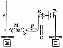
In this way we have an arrangement (see Fig. 19) in which the outer extremity of this open spiral experiences variations or potential which exactly correspond with those at the summit of the vertical aerial. The receiving arrangements are then completed as in Fig. 19, one end of the coherer being attached to the outer end of the spiral and the other end through a condenser to the earth, a relay and a voltaic cell being arranged as shown in the diagram. The mode of operation of this receiver is as follows: When the wave strikes the aerial it sets up in it electrical oscillations with a potential antinode at the summit, and at the same time a potential antinode is created at the outer end of the spiral attached near the base of the aerial, this spiral being called by Professor Slaby a multiplicator. As long as the coherer tube remains non-conductive, the local cell cannot send a current through the relay, but, as soon as the resistance is broken down by the impact of a wave, the local cell sends a current through the coherer tube which, passing down to the earth through the base of the aerial and up through the earth connection to the condenser, completes its circuit through the relay. Many variations of this arrangement have been made by Slaby and Von Arco and by the Allgemeine Elektricitäts Gesellschaft of Berlin.
In 1898, Mr. Marconi made a great advance in the construction of his receiving apparatus by the insertion of his "jigger" or oscillation transformer in the aerial receiving circuit.[57] In this arrangement, the primary coil of an air core transformer wound in a particular way is inserted between the receiving aerial and the earth, and the secondary circuit is cut in the middle and connected to the two surfaces of a condenser, these surfaces being also connected through the circuit of an ordinary telegraphic relay and a single cell (see Fig. 20). The ends of the secondary circuit of this oscillation transformer are also connected to the terminals of the coherer tube, and these again are short-circuited by a small condenser.
Fig. 20.—Marconi Receiver. A, aerial; J, jigger; CC, condensers; F, filings tube; T, tapper; R, relay; B, battery; M, Morse printer.
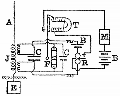
The operation of this receiver is as follows: The oscillations set up in the aerial pass through the primary circuit of the jigger, and these induce other oscillations in the secondary circuit; the electromotive force or difference of potential between the primary terminals being transformed up in any desired ratio. It is this exalted electromotive force which is made to act on the coherer tube, and, inasmuch as the jigger operates in virtue of a current passing through its primary circuit and this current is at a maximum at the lower end of the aerial, the arrangement is exceedingly effective, because it, so to speak, converts current into voltage. At the lower end of the aerial, although the amplitude of the potential oscillations is a minimum, the amplitude of the current oscillations is a maximum, and the jigger transforms these large current oscillations into large potential oscillations, provided it is constructed in the right manner. We can also transform up or increase the amplitude of the small potential variations near the bottom of the aerial by employing the principle of resonance. Many devices of this kind, due to Professor Slaby and others, have been suggested and tried but the details are rather too technical to be fully described here.
It will be noticed that the receiving aerial may be arranged in one of two ways—it may be either earthed at the lower end or it may be insulated. It has been claimed that there is a great advantage in earthing the receiving aerial directly in that it eliminates atmospheric disturbances.
We shall allude to this point more particularly later on. Meanwhile it may be mentioned that the receiving arrangements, as a whole, constitute a sensitive arrangement, as shown by Popoff, Tommasina and by all the large experience of Mr. Marconi himself for detecting changes in the electrical condition of the atmosphere, which are doubtless of the nature of electrical oscillations. On the other hand, the receiving arrangements may be perfectly insulated and some experimentalists have asserted that by this method the greatest freedom is secured from atmospheric disturbances. Amongst the non-earthed arrangements the system invented by Professor F. Braun, of Strassburg, and worked by Messrs. Siemens, of Berlin, may be mentioned.[58]
Fig. 21.—Braun's Non-earthed Receiver. I, induction coil; CC, condensers; S, spark gap; J, transmitting jigger; K, receiving jigger; F, filings tube; R, relay; B, battery.
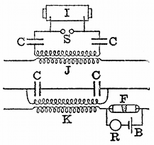
Professor Braun's arrangements are indicated in the diagram in Fig. 21. In this case an induction coil is used to create a discharge between two spark balls, and to these two balls are connected the two outer coatings of two condensers, the inner coatings of which are connected together through the primary coil of an air core transformer. The secondary coil of this transformer is connected to two extension wires forming a Hertz resonator, and the length of these wires is so adjusted with reference to the time period of the primary circuit that they resonate to it, the whole length from end to end of the secondary circuit being half a wave-length. The receiver, as shown in the diagram, consists of a pair of quarter wave-length receiving wires connected through two condensers, which are short-circuited by the primary coil of an oscillation transformer. The secondary circuit of this last oscillation transformer has two extension wires to it, turned in the same manner, to respond to the primary oscillator; and in the circuit of one of these extension wires is placed a coherer tube, short-circuited by a relay and a local battery.
It will thus be seen that there is an entire abolition of ground connection, which, Professor Braun claims, practically avoids all atmospheric disturbances.[59] The details of the receiving arrangement are as follows:—The coherer tube consists of an ebonite tube containing hard steel particles of a uniform size, placed in the adjustable space between two polished steel electrodes. It is found that with this steel coherer, a small amount of magnetism in the particles increases its sensitiveness, and to obtain this, a ring magnet is employed in connection with a coherer tube. Receiving apparatus arranged on this system is said to have been used for telegraphing between Heligoland and Cuxhaven, a distance of thirty-six miles.
All the immense experience, however, gained by Mr. Marconi and those who have worked with his system, is in favour of using the earth connection. There is no doubt that Hertzian wave telegraphy can be conducted over short distances by means of totally insulated aerials, but for long distances the earth connection is essential, for the reasons that have been explained previously.
There are many of the details of the receiving arrangements which remain to be considered. If the communication is received by a telegraphic instrument like the Morse printer, which requires a current of anything like ten milliamperes to work it, then an important element in the receiving arrangement is the relay. The relay that is generally used is a modified form of the Siemens polarised relay, which is so adjusted as to make a single contact. For marine work on board ship, it is essential that this relay shall be balanced so that variations in position shall not affect it. Sometimes the relay is hung in gimbals like a compass, and at other times suspended from a support by elastic bands, so as to avoid jolting. In any case, the relay must be so adjusted that no change of position will cause it to close the circuit of the telegraphic printer or recorder. Its sensibility ought to be such that it is actuated by a tenth of a milliampere, and, if possible, even by less. The alteration of sensibility in the ordinary contact form of relay is the pressure that is necessary to bring the platinum points of the circuit closer together, so as to pass the minimum current which will work the telegraph printer.
The important matter, however, in connection with the use of the relay in Hertzian wave telegraphy, is that it should be capable of adjustment without extraordinary skill. It is no use to put into the hands of an operator a relay which requires abnormal dexterity to make it work at all.
It remains, then, to consider some of the questions connected with practical Hertzian wave telegraphy and the problem of the limitation of communication. These matters at the present moment very much occupy the public attention, and many conflicting opinions are expressed concerning them.
It may be observed at the outset that the difficulty of dealing with the subject as freely as many desire is that Hertzian wave telegraphy is no longer merely a subject of scientific investigation, but has developed into a business and involves, therefore, other interests than the simple advancement of scientific knowledge. We can, however, discuss in a general manner some of the scientific problems which present themselves for solution. The first of these is the independence of communication between stations. It is desirable, at the outset, to clear up a little misunderstanding. There is a great difference between preventing the reception of communication when it is not desired by the recipient, and preventing it when it is the object of the latter to overhear if he can. It is, therefore, necessary to distinguish between isolation and overhearing. We may say that a station is isolated when it is not affected by Hertzian waves other than those it desires to receive; but that a station overhears when it can, if it chooses, pick up communications not intended for it, or cannot help receiving them against its will.
This distinction is a perfectly fair one. Any telegraph or telephone wire can be tapped, if it is desired, but unless there is some fault on the line, no station will receive a message against its desires. Moreover, it may be noted that there are penalties attached to tapping a telegraph wire, and at present there are none connected with the misappropriation of an ether wave.
We shall, therefore, consider in the first place the methods so far proposed for preventing any given receiver from being affected by Hertzian waves sent out from other stations, except that of those from which it is desired to receive them. The first method is that which has been called the method of electrical syntony, and consists in adjusting the electrical capacity and inductance of the various open and closed circuits of the receiving and transmitting stations to be put in communication so that they have the same electrical time-period.[60]
In the Cantor Lectures before the Society of Arts in 1900, on electrical oscillations and electric waves, the author has discussed at length the conditions under which powerful electrical oscillations can be set up in a circuit. It was there shown that every electric circuit having capacity and inductance has a particular or natural time-period of electrical oscillation depending on the product of these qualities, and that, to accumulate powerful electrical oscillations in it, the electromotive impulses on it must be delivered at this rate. Illustrations were drawn from mechanics, such as the examples furnished by vibrating pendulums and springs, and from acoustics, as illustrated by the phenomena of resonance, to show that small or feeble blows or impulses delivered at the proper time intervals have a cumulative effect in setting up vibrations in a body capable of oscillation. It is a familiar fact that if we time our blows, we can achieve that which no single blow, however powerful, can accomplish in throwing into vibration a body such as a pendulum, which is capable of oscillation under the action of a restoring force. Precisely the same is true of an electric circuit. We have already seen that the receiving aerial has an alternating electromotive force set up in it by the impact of the successive electric waves sent out from the transmitter. It must, however, be remembered that the transmitter sends out a series of trains of waves, not by any means a continuous train, but one cut up into groups of probably ten to fifty waves, each separated by intervals of silence, long, compared with the duration of a single train of waves.
Fig. 22.—Seibt's Apparatus for Exhibiting Electric Resonance. I, induction coil; S, spark gap; CC, condensers; L, variable inductance; E, earth plate; WW, wire spirals; VV, vacuum tubes.
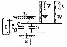
If, however, by a suitable adjustment of capacity and inductance, we make the natural time-period of oscillation of the receiving aerial circuits agree with those of the transmitting aerial, within certain limits the former will only be receptive for waves of the frequency sent out by the transmitter. It is quite easy to illustrate this principle by numerous experiments. It can be done by means of an apparatus devised by Dr. Georg Seibt for showing in an interesting manner the syntonisation or tuning of two electric circuits. This consists of two bobbins, each consisting of one layer of insulated wire wound on a wooden rod (see Fig. 22). Each of these bobbins has a certain electrical capacity with respect to the earth, when considered as an insulated conductor, and it has also a certain inductance. If, therefore, electromotive impulses are applied to one end of the bobbin at regular intervals, electrical oscillations will be set up in it, and, as already explained, if these are timed at a certain rate, the bobbin will act like a closed organ-pipe to air impulses and oscillations of potential will be accumulated at the opposite end, which have much greater amplitude than the impressed oscillations at the end at which they are applied. We can make the existence of the amplitude oscillations of potential evident by attaching to one end of the bobbin a vacuum tube, which will be illuminated thereby, or by terminating it by a pointed piece of wire, so that an electrical brush can be formed at the point, if the potential variations have sufficient amplitude. We arrange also another closed oscillation circuit, consisting of two Leyden jars and a variable inductance coil and a pair of spark balls which are connected to an induction coil. In this manner we can set up oscillations in the discharge circuit of these Leyden jars, and we can vary the time period by altering the inductance and the capacity. If we denote the capacity of the jars in the microfarads by the letter C and the inductance in centimetres of the discharge circuit of the jars by the letter L, it can then be shown that the number of oscillations per second denoted by n is given by the expression—[61]
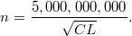
If now we adjust the Leyden jar circuit to a particular rate of oscillation, we have between the terminals of the jar or condenser an alternating difference of potential or electromotive force. If we connect one side of the jars to the earth and the other side to the foot of one of the spirals or bobbins above described, we shall find perhaps that the vacuum tube at the other end is not rendered luminous. When, however, we adjust the inductance in the discharge circuit of the jar to a certain value to make the frequency of the condenser oscillations agree with the natural time period of the bobbin terminated by the vacuum tube, this latter at once lights up brilliantly. Again, if we connect both these bobbins at the same time to the discharge circuit of the Leyden jar, we shall find that we can make an adjustment of the inductance of that circuit, such that either of the bobbins at pleasure can be made to respond and be set in electrical vibration, as shown by the illumination of the vacuum tube at its upper end or by an electrical brush being formed at the terminal. In making this adjustment of inductance, we are tuning, as it is called, the Leyden jar discharge circuit to the resonating bobbin. A very small variation of the inductance of the jar circuit causes the vacuum tube to change in luminosity. If, however, the natural time periods of these bobbins do not lie very far apart, then a faint luminosity will make its appearance in both the vacuum tubes. Supposing, therefore, that we connect to the oscillating circuit of the jar a number of bobbins having different time periods of oscillation, like organ-pipes, and supply them all with one common alternating electromotive force. These bobbins, whose natural time period is very different to that of the osciilating circuit or impressed electromotive force, will not respond, but those bobbins of which the natural time period lies near to, even if not quite exactly the same as, that of the impressed electromotive force will give evidence of being set in oscillation. A very violent electromotive force will cause them all to respond to some slight extent, no matter whether the period of that impluse is tuned to their common period precisely or not.
At this point questions arise of great practical importance. A matter which has been in dispute in connection with practical Hertzian wave telegraphy is how far this electrical tuning is a sufficient solution of the practical problem of isolation. It is not denied that experiments such as those made with Seibt's apparatus can be shown on a small scale; and, on a still larger scale, Mr. Marconi gave to the author in September, 1900, a demonstration in practical telegraphic work of sending two independent Hertzian wave messages and receiving them on two independent receivers attached to the same aerial.
Since that date much experience has been gained and large power stations erected, and a statement has been frequently made that syntony is no protection against interference when one of the stations is sending out very powerful waves. The contention has been raised that large power stations producing electric waves will therefore play havoc with Hertzian wave telegraphy on a smaller scale, such as the ship to shore and intermarine communication. Under these circumstances, it appeared to the author important to subject the matter to a special test, and Mr. Marconi, therefore, offered to give a demonstration, with this object, in support of the opinion that he has expressed positively that waves from his power stations do not interfere with the working of his ship installations. This matter is vital to the whole question of practical Hertzian wave telegraphy, for the ship to shore communication is of stupendous importance; and if Mr. Marconi had done nothing else except to render this possible and effective, he would have earned, as he has done, the gratitude of humanity for all time. Accordingly, the author embraced the opportunity of making some careful tests to settle the question whether the powerful waves sent out from a station such as Poldhu did or did not affect the exchange of messages between ship and shore stations in proximity, equipped with Marconi apparatus of a suitable type.
These experiments were carried out on the eighteenth of March last, at Poldhu, in Cornwall, and a programme was arranged by the author of the following kind. Close to the Poldhu station is an isolated mast, which was equipped by Mr. Marconi with a Hertzian wave apparatus, similar to that he places on ships. Six miles from Poldhu is the Lizard receiving station, with which ships proceeding up or down the English Channel communicate. It was arranged that a series of secret messages, some of them in cipher, should be delivered simultaneously at certain known times, both to the power station at Poldhu and to the small adjacent ship station; and it was arranged that these messages should be sent off simultaneously, the operators being kept in ignorance up to the moment of sending as to the nature of the messages. At the Lizard, Mr. Marconi connected two of his receiving instruments to the aerial, one of them tuned to the waves proceeding from the power station at Poldhu, and the other to those proceeding from the small ship station. At the appointed time, these two sets of messages were received simultaneously in the presence of the author, each message being printed down independently on its own receiver; and Mr. Marconi read off and interpreted all these messages perfectly correctly, not having known before what was the message that was about to be sent. In addition to this, precautions were taken to prove that the power station at Poldhu was really emitting waves sufficiently powerful to cross the Atlantic and not being made to sing small for the occasion. To assist in proving this, the messages sent out from the power station were also received at a station at Poole, two hundred miles away, and the assistant there was instructed to telegraph back these messages by wire as soon as he received them. These messages came back perfectly correctly, thus demonstrating that the power station was sending out power waves. The whole programme was carried out with the greatest care to avoid any mistakes on the part of the assistants, and provided an absolute demonstration of the truth of Mr. Marconi's assertion that the waves from one of his power stations, such as Poldhu, do not in the least degree interfere with the transmission and reception of messages between ship and shore, effected by means of certain forms of Marconi apparatus for producing and detecting waves of a different wave length.[62] This complete independence of transmission, however, is entirely due to the employment of a receiving circuit of a certain type in Mr. Marconi's receivers. It does not at all follow that a receiving circuit of any kind, even a Marconi receiver not especially arranged, set up in proximity to a power station would not be affected. This, however, is not an important matter. Far more important is it to show, as has been shown, that practically perfect isolation can be achieved if it is desired.
It must be noted, however, that, although the fact that electric circuits have a natural time-period of oscillation of their own is a scientific principle which carries us a considerable way towards a solution of what is called syntonic Hertzian wave telegraphy, it is not in itself alone in every respect an entire solution of the practical problem. The degree to which it is a solution depends to a considerable extent upon the nature of the detecting device, or kumascope, which we are employing. The coherer, or Branly filings tube, has the peculiarity that its passage from a non-conductive to a conductive condition follows immediately when the difference of potential between its ends is made sufficiently great. In other words, if the tube is acted upon by a sufficient electromotive force, it is not necessary that electromotive force should be repeated at intervals to make this particular form of kumascope responsive. Again, if we consider the nature of the oscillations which are sent out from any transmitting aerial, we find that each group of oscillations corresponding to a single spark consists of waves gradually decreasing in amplitude. In other words, the first wave of the group is the strongest, and the decay in amplitude is often very rapid. Supposing, then, we construct a simple receiver consisting of an aerial having inserted in its circuit a sensitive Branly filings tube. Such a receiver is almost entirely non-syntonic; that is to say, it is affected by any wave passing over it which is sufficiently powerful. We may look upon it that if the first wave of the series is sufficiently powerful to affect the kumascope, the conductive change takes place whether or not the first wave is followed by others. Accordingly, it is perfectly certain that if a transmitter is sending out trains of waves of any period, a simple combination of coherer and aerial will be influenced, if it is placed near enough to the transmitter. On the other hand, it is possible to combine a kumascope of a certain type with a receiving aerial and other circuits in such a manner that when the waves that reach it are feeble it shall not respond at all unless those waves have very nearly a time period of a certain value.
At this stage, it may be perhaps well to explain a little in detail what is meant by an easily responsive circuit, and, on the other hand, by an irresponsive circuit, or, as we may call it, a stiff circuit. Supposing that we consider an aerial consisting of a simple straight wire having small capacity and small inductance, such a circuit admits of being sent into electrical oscillation, not only by waves of its own natural time-period, but by the sudden application of any violent electromotive impulse. If, on the other hand, we bestow upon the circuit in any way considerable inductance, we then obtain what may be called a stiff or irresponsive circuit, which is one in which electrical oscillations can be accumulated only by the prolonged action of impulses tuned to a particular period.
A mechanical analogue of this difference may be found in considering the different behaviour of elastic bodies to mechanical blows. Take, for instance, a piece of elastic steel and fix the bottom end in a vice. The steel strip may be thrown into vibration by deflecting the upper end. It has, however, a very small mass, and therefore any violent blow or blows, even although not repeated, will set it in oscillation. If, however, we add mass to it by fixing at the other end a heavy weight, such as a ball of lead, and at the same time make the spring stiffer, we have an arrangement which is capable of being sent into considerable oscillation only by the action of a series of impulses or blows which are timed at a particular rate.
Returning then to the electrical problem, we see that in order to preserve a kumascope or wave detector from being operated on by any vagrant wave or waves having a period very different to an assigned period, it must be associated with an electrical circuit of the kind above called a stiff circuit.
We will now consider the manner in which the problem has been practically attacked by Mr. Marconi, Dr. Slaby, Sir Oliver Lodge and others, who have invented forms of receiver and transmitter, which are syntonic or sympathetic to one another.
Some of the methods which Mr. Marconi has devised for the achievement of syntonic wireless telegraphy were fully described by him in a Paper read before the Society of Arts on May, 17, 1901.[63]
Fig. 23.—Marconi Transmitter and Receiver. I, induction coil; A, aerial; E, earth plate; HH, choking coils; S, spark gap; J, transmitting jigger; K, receiving jigger; R, relay; C, condenser; F, filings tube; B, battery. Many practical details are omitted.
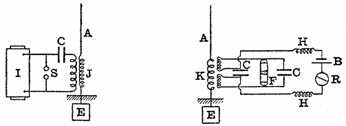
On referring to his Paper, it will be seen that in one form his transmitter consists of an aerial, near the base of which is inserted the secondary circuit of an oscillation transformer or transmitting jigger. One end of this secondary circuit is attached to the aerial and the other end is connected to the earth through a variable inductance coil. The primary circuit of this oscillation transformer is connected in series with a condenser, consisting of a battery of Leyden jars, and the two together are connected across to the spark balls which close the secondary circuit of an induction coil, having the usual make and break key in the primary circuit. Mr. Marconi so adjusts the induction of the aerial and the capacity of the condenser, or battery of Leyden jars, that the two circuits, consisting respectively of this battery of Leyden jars and the primary circuit of the transformer, and on the other hand of the capacity of the aerial and the inductance in series with it, and that of the secondary circuit of the transformer have the same time period. In other words, these two inductive circuits are tuned together. At the receiving end, the aerial is connected in series with a variable inductance and with the primary circuit of another oscillation transformer, the second terminal of which is connected to the earth. The secondary circuit of this last oscillation transformer is cut in the middle and is connected to the terminals of a small condenser. The outer terminals of this secondary circuit are connected to the metallic filings tube or other sensitive receiver and to a small condenser in parallel with it (see Fig. 23). The terminals of the condenser which is inserted in the middle of the secondary circuit of the oscillation transformer are connected through two small inductance coils with a relay and a single cell. This relay in turn actuates a Morse printer by means of a local battery. The two circuits of the oscillation transformer are tuned or syntonised to one another, and also to the similar circuit of the transmitting arrangement. When this is the case, the transmitter affects the co-resonant receiving arrangement, but will not affect any other similar arrangement, unless it is within a certain minimum range of distance. Owing to the inductance of the oscillation transformer forming part of the receiving arrangements, the receiving circuit is, as before stated, very stiff or irresponsive; the sensitive tube is therefore not acted upon in virtue merely of the impact of the single wave against the aerial, but it needs repeated or accumulated effects of a great many waves, coming in proper time, to break down the coherer and cause the recording mechanism to act. An inspection of the diagram will show that as soon as the secondary electromotive force in the small oscillation transformer or jigger of the receiving instrument is of sufficient amplitude to break down the resistance of the coherer, the local cell in circuit with the relay can send a current through it and cause the relay to act and in turn make the associated telegraphic instrument record or sound.
Mr. Marconi described in the above-mentioned Paper some other arrangements for achieving the same result, but those mentioned all depend for their operation upon the construction of a receiving circuit on which the time-period of electrical oscillations is identical with that of a transmitting arrangement. By this means he showed experiments during the reading of his Paper, illustrating the fact that two pairs of transmitting and receiving arrangements could be so syntonised that each receiver responded only to its particular transmitter and not to the other.
With arrangements of substantially the same nature, he made experiments in the autumn of 1900 between Niton, in the Isle of Wight, and Bournemouth, a distance of about thirty miles, in which independent messages were sent and received on the same aerial.
Dr. Slaby and Count von Arco, working in Germany, have followed very much on the same lines as Mr. Marconi, though with appliances of a somewhat different nature. As constructed by the General Electric Company, of Berlin, the Slaby-Arco syntonic system of Hertzian telegraphy is arranged in one form as follows:—The transmitter consists of a vertical rod like a lightning conductor, say, 100 or 150 feet in height. At a point six or nine feet above the ground, a connection is made to a spark ball (see Fig. 24), and the corresponding ball is connected through a variable inductance with one terminal of a condenser, the other terminal of which is connected to the earth. The two spark balls are connected to an induction coil, or alternating current transformer, and by variation of the inductance and capacity the frequency is so arranged that the wave-length corresponding to it is equal to four times the length of that portion of the aerial which is above the spark ball connection. The method by which this tuning is achieved is to insert in the portion of the aerial below the spark balls, between it and the earth, a hot wire ammeter of some form. It has already been shown that in the case of such an earthed aerial, when electrical oscillations are set up in it, there is a potential node at the earth and a potential anti-node or loop at the summit, if it is vibrating in its fundamental manner; also, there is a node of current at the summit of the aerial and an anti-node at the base. This amounts to saying that the amplitude of the potential vibrations is greatest at the top end of the aerial, and the amplitude of the current vibrations is greatest at the bottom or earthed end. Accordingly, the inductance and capacity of the lateral branch of the transmitter is altered until the hot wire ammeter in the base of the aerial shows the largest possible current.
Fig. 24.—Slaby-Arco Syntonic Transmitter and Receiver. I, induction coil; M, multiplier; B, battery; A, aerial; F, filings tube; R, relay; E, earth plate; C, condenser.
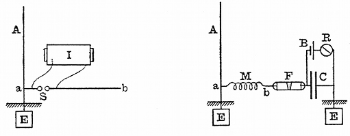
The corresponding receiver is constructed in a very similar manner. A lightning conductor or long vertical rod of the same height as the transmitting aerial is set up at the receiving station, and at a point six or nine feet from the ground a circuit is taken off, consisting of a wire loosely coiled in a spiral, the length of which is nearly equal to, although a little shorter than, the height of the vertical wire above the point of connection. The outer end of this loose spiral is connected to one terminal of the coherer tube, and the other terminal of the coherer is connected to the earth through a condenser of rather large capacity. The terminals of this last condenser are short-circuited by a relay and a single cell. When the adjustments are properly made, it is claimed that the receiver responds only to waves coming from its own syntonised or tuned transmitter. In this case the length of the receiving aerial above the point of junction with the coherer circuit is one quarter the length of the wave. A variation of the above arangements consists in making this lateral circuit equal in length to one-half of a wave, and connecting the coherer to its centre through a condenser to the earth. The outer end of this lateral circuit is also connected to the earth (see Fig. 24).[64]
Dr. Slaby claims that this arrangement is not affected by atmospheric electricity, and that the complete and direct earthing of the aerial and also in the second arrangement, of the receiver of the outer end of the lateral conductor, conduces to preserve the receiver immune from any electrical disturbances except those having a period to which it is tuned.
A method has also been arranged by him for receiving on the same aerial two messages from different transmitting stations simultaneously. In this case, two lateral wires of different lengths are connected to the receiving aerial, and to the outer end of each of these is connected a coherer tube, the other end of which is earthed through a condenser. One of these lateral wires is made equal, or nearly equal, in length to the aerial, and the other is made longer to fulfil the following condition.[65] If we call H the height of the receiving aerial above point of junction of the lateral wires, then the length of one lateral wire is made equal to H, and the height of the aerial is adjusted to be equal to one-quarter of the wave length of one incident wave. The other lateral wire may then be made of a length equal to one-third of H, and it will then respond to the first odd harmonic of that wave, of which the fundamental is in syntony with the vertical wire. By suitably choosing the relation between the wave-lengths of the two transmitting stations, it is possible to receive in this manner two different messages at the same time on the same aerial. Subsequently to the date of the above-mentioned demonstration of multiplex wireless telegraphy by Mr. Marconi an exhibition of a similar nature was given by Professor Slaby in a lecture given in Berlin on December 22, 1900.[66]
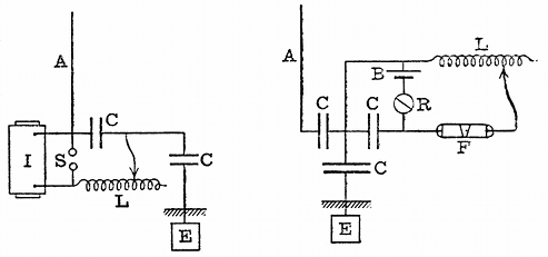
Fig. 25.—Lodge-Muirhead Syntonic Receiver. I, induction coil; S, spark gap; A, aerial; CC, condensers; E, earth plate; R, relay; L, variable inductance; F, filings tube; B, battery.
Both the above-described syntonic systems of Mr. Marconi and Dr. Slaby are "earthed" systems, but arrangements for syntonic telegraphy have been devised by Sir Oliver Lodge and Professor Braun which are "non-earthed."
Sir Oliver Lodge and Dr. Muirhead have devised also syntonic systems. According to their last methods, the systonic transmitting and receiving arrangements are as shown in Fig. 25.[67] On examining the diagrams it will be seen that the secondary terminals of the induction coil are, as usual, connected to a pair of spark balls, and that these spark balls are connected by a condenser and by a variable inductance. One terminal of the condenser is earthed through another condenser of large capacity, and the remaining terminal of the first condenser is connected to an aerial. It should, therefore, be borne in mind in dealing with electrical oscillations that a condenser of sufficient capacity is practically a conductor, and an inductance coil of sufficient inductance is practically a non-conductor. Hence the insertion of a large capacity in the path of the aerial wire is no advantage whatever and makes no essential difference in the arrangement. In order to obtain any powerful radiation, the length of the aerial, or sky wire, as they call it, must be so adjusted that its length is one-quarter the wave-length corresponding to the oscillation circuit, consisting of the condenser and variable inductance.
The receiving arrangement consists of a similar sky wire or aerial earthed through a condenser of large capacity and having in the portion above this last condenser another condenser of similar capacity. At the earthed side of this last condenser a connection is made to a resonant circuit, consisting of a variable inductance, and another condenser and a sensitive metallic filings tube of the Branly type; also a portion of this resonant circuit is shunted by another consisting of a battery and telegraphic relay, as shown in the diagram. The circuit, including the coherer, is tuned to its own aerial and also to that of the transmitting circuit, and under these circumstances trains of waves thrown off at the transmitting aerial will sympathetically affect the receiving aerial.
There is nothing in the arrangement which specially calls for notice. It is simply a variation of other known forms of syntonic transmitter and receiver, and possesses all the advantages and disadvantages attaching to such electrical syntonic methods.
Professor Braun's syntonic system, the receiver and transmitter of which have been described, is also in one form a non-earthed system. Innumerable other patentees have taken out patents for devices which are modifications in small degree of the above arrangements.
It may be well to note at this point the disadvantages that are possessed by any form of coherer as a telegraphic kumascope in connection with proposed arrangements for the isolation of Hertzian wave stations. All the detectors of the coherer type really depend for their actuation upon electromotive force; that is to say, upon the application to the terminals of the detector of a certain electromotive force. Although there may be no sharp and defined critical electromotive force, yet, nevertheless, as a matter of fact, if the electromotive force applied exceeds a certain value, then the detector passes suddenly from one state of conductivity to another. It may be of great conductivity, as in the case of the Branly coherer, or of lesser conductivity, as in the case of the so-called anti-coherers, of which the Schäfer kumascope may be taken as a type. Accordingly, when these instruments are subjected to a train of waves, each individual group of which is damped, their operation is largely governed by the fact that if the first wave or oscillation set up in the receiving circuit is powerful enough to break down the coherer, then the receiving mechanism acts, no matter whether the first impulse is followed by others or not.
In comparison with so-called coherers, those depending upon the changes in the magnetisation of iron by electrical oscillations certainly have an advantage, because this is a process which requires the application of alternating electric currents decreasing in strength for a certain time; and it is found, therefore, that the magnetic receivers do not require to be associated with such a stiff or irresponsive resonant circuit to confine their indications to oscillations or waves of one definite period, and that they lend themselves much more perfectly to the work of "tuning" or syntonising stations than do those kumascopes depending upon the contact or coherer principle.
We may then glance at the alternative solutions of the problem offered by other investigators. M. Blondel has proposed to effect the syntonisation of two stations, not by syntonising the receiver for the exceedingly high-frequency oscillations of the individual electric waves, but to syntonise it for the much lower frequency, corresponding to that of the intervals between the groups of waves. Thus, for instance, if an ordinary simple transmitting aerial is set up, the production of sparks between the spark balls results in the emission of short trains of waves, each of which may consist of half a dozen or more individual waves, the time of production of the whole group being very small compared with the interval between the groups. M. Blondel proposes, however, to syntonise the receiver, not for the high-frequency period of the waves themselves, which may be reckoned in millions per second, but for the low-frequency period between the groups of waves, which is reckoned in hundreds per second. Thus, for instance, if sparks are made at the rate of fifty or a hundred per second, they can be made to actuate the telephone receiver and so produce in the telephone a sound corresponding to a frequency of 50 or 100; in other words, to make a low musical note or hum. This continuous sound can be cut up, by means of a key placed in the primary circuit of the transmitting arrangement, into long or short periods, and hence the letters of the alphabet signal.
M. Blondel's arrangements comprise a Mercadier's monotone telephone and either a coherer or a particular form of vacuum tube as a kumascope. On August 16, 1898, M. Blondel deposited with the Academy of Sciences in Paris a sealed envelope containing a description of his improvements in syntonic wireless telegraphy, which was opened on May 19, 1900.[68] The arrangement of the receiving apparatus was as follows:—A single-battery cell keeps a condenser charged until the kumascope is rendered conductive by the oscillations coming down the aerial; and under these circumstances the condenser discharges through the telephone and causes a tick to be heard in it. If the trains of waves are at the rate of 50 or 100 per second, these small sounds run together into a musical note, and this continuous hum can be cut up into long and short spaces, in accordance with the Morse alphabet signals. The telephone must not be an ordinary telephone, capable of being influenced by any frequency, but be one which responds only to a particular note, and under these conditions the receiving arrangement is receptive only when the trains of waves arrive at certain regular predetermined intervals, corresponding with the tone to which the telephone is sensitive.
A number of more or less imperfect arrangements, having the isolation of communications for their object, have been devised or patented, which are dependent upon the use of several aerials, each supposed to be responsive only to a particular frequency; and attempts have been made to solve the problem of isolation by MM. Tommasi, Tesla, Jegon, Tissot, Ducretet and others.
We may then pass on to notice the attempts that have been made to secure isolation by a plan which is not dependent on electrical syntony. One of these, which has the appearance of developing into a practical solution of the problem, is that due to Anders Bull.[69] In the first arrangements proposed by this inventor, a receiver is constructed which is not capable of being acted upon merely by a single wave or train of waves or even a regularly-spaced train of electric waves, but only by a group of wave trains which are separated from one another by certain unequal, predetermined intervals of time. Thus, for instance, to take a simple instance, the transmitting arrangements are so devised as to send out groups of electric waves, these wave trains following one another at time intervals which may be represented by the numbers 1, 3 and 5; that is to say, the interval which elapses between the second and third is three times that between the first two, and the interval between the fourth and fifth is five times that between the first two. This is achieved by making five electric oscillatory sparks with a transmitter of the ordinary kind, the intervals between which are settled by the intervals between holes punched upon strips of paper, like that used in a Wheatstone automatic telegraphic instrument. It will easily be understood that by a device of this kind, groups of sparks can be made, say, five sparks rapidly succeeding each other, but not at equal intervals of time. One such group constitutes the Morse dot, and two or three such groups succeeding one another very quickly constitute the Morse dash. These waves, on arriving at the receiving station, are caused to actuate a punching arrangement by the intermediation of a coherer or other kumascope, and to punch upon a uniformly moving strip of paper holes, which are at intervals of time corresponding to the intervals between the sparks at the transmitting station. This strip of paper then passes through another telegraphic instrument, which is so constructed that it prints upon another strip a dot or a dash, according to the disposition of the holes on the first strip. Accordingly, taken as a whole, the receiving arrangement is not capable of being influenced so as to print a telegraphic sign except by the operation of a series of wave trains succeeding one another at certain assigned intervals of time.
An improvement has been lately described by the same inventor,[70] in which the apparatus used, although more complicated, performs the same functions. At each station two instruments have to be employed; at the transmitting station one to effect the conversion of Morse signals into the properly arranged series of wave trains, and at the receiving station an instrument to effect the re-conversion of the series of wave trains into the Morse signals. These are called respectively the dispenser and the collector. The details of the arrangements are somewhat complicated, and can only be described by the aid of numerous detailed drawings, but the inventor states that he has been able to carry on Hertzian wave telegraphy by means of these arrangements for short distances. Moreover, the method lends itself to an arrangement of multiplex telegraphy, by sending out from different transmitters signals which are based upon different arrangements of time intervals between the electric wave trains. Although this method may succeed in preventing a receiving arrangement from being influenced by vagrant waves or waves not intended for it, yet an objection which arises is that there is nothing to prevent any one from intercepting these wave trains, and with a little skill interpreting their meaning. Thus, if the record were received in the ordinary way on a simple receiver, corresponding to a Morse dot would be printed five dots at unequal intervals, and corresponding to a Morse dash would be printed two such sets of five dots. A little skill would then enable an operator to interpret these arbitrary signals. On the other hand, the inventor asserts that he can overcome this difficulty by making intervals of time between the impulses in the series so long that the latter become longer than the intervals between each of the series of waves which are despatched in continuous succession when the key is pressed for a dash. In this case, when telegraphing, the series of dots would overlap and intermingle with each other in a way which would make the record unintelligible if received in the usual manner, but would be perfectly legible if received and interpreted by a receiver adapted for the purpose.
Another way of obliterating the record, as far as outsiders are concerned, is to interpolate between the groups of signals an irregular series of dots—i.e., of wave trains—which would affect an ordinary coherer, and so make an unintelligible record on an ordinary receiver, but these dots are not received or picked up by the appropriate selecting instrument used in the Anders Bull system.
The matter most interesting to the public at the present time is the long-distance telegraphy by Hertzian waves to the accomplishment of which Mr. Marconi has devoted himself with so much energy of late years. Everyone, except perhaps those whose interests may be threatened by his achievements, must accord their hearty admiration of the indomitable perseverance and courage which he has shown in overcoming the immense difficulties which have presented themselves. Five years ago he was engaged in sending signals from Alum Bay, in the Isle of Wight, to Bournemouth, a distance of twelve or fourteen miles; and to-day he has conquered twice that number of hundred miles and succeeded in sending, not merely signals, but long messages of all descriptions over three thousand miles across the Atlantic. Critics there are in abundance, who declare that the process can never become a commercial one, that it will destroy short-distance Hertzian telegraphy, or that the multiplication of long-distance stations will end in the annihilation of all Hertzian wave telegraphy. No one, however, can contemplate the history of any development of applied science without seriously taking to heart the lesson that the obstacles which arise and which prove serious in any engineering undertaking are never those which occur to armchair critics. Sometimes the seemingly impossible proves the most easy to accomplish, whilst difficulties of a formidable nature often spring up where least expected.
The long-distance transmission is a matter of peculiar interest to the author of these articles, because he was at an early stage in connection with it invited to render Mr. Marconi assistance in the matter.[71] The particular work entrusted to him was that of planning the electrical engineering arrangements of the first power station erected for the production of electric waves for long-distance Hertzian wave telegraphy at Poldhu, in Cornwall. When Mr. Marconi returned from the United States in the early part of 1900, he had arrived at the conclusion that the time had come for a serious attempt to accomplish wireless telegraphy across the Atlantic. Up to that date the project had been an inventor's dream, much discussed, long predicted, but never before practically taken in hand. The only appliances, moreover, which had been used for creating Hertzian waves were induction coils or small transformers, and the greatest distance covered, even by Mr. Marconi himself, had been something like 150 miles over sea. Accordingly, to grapple with the difficulty of creating an electric wave capable of making itself felt at a distance of 3,000 miles, even with the delicate receiving appliances invented by Mr. Marconi, seemed to require the means of producing at least four hundred times the wave-energy that had been previously employed. The author was, therefore, requested to prepare plans and specifications for an electric generating plant for this purpose, which would enable electrical oscillations to be set up in an aerial on a scale never before accomplished.
This work involved, not merely the ordinary experience of an electrical engineer, but also the careful consideration of many new problems and the construction of devices not before used. Every step had to be made secure by laboratory experiments before the responsibility could be incurred of advising on the nature of the machinery and appliances to be ordered. Many months in the year 1901 were thus occupied by the author in making small-scale experiments in London and in superintendence of large-scale experiments at the site of the first power station at Poldhu, near Mullion, in Cornwall, before the plant was erected and any attempt was made by Mr. Marconi to commence actual telegraphic experiments. As this work was of a highly confidential nature, it is obviously impossible to enter into the details of the arrangements, either as made by the writer in the first instance, or as they have been subsequently modified by Mr. Marconi. The design of the aerial and of the oscillation transformers and many of the details in the working appliances are entirely due to Mr. Marconi, but as a final result, a power plant was erected for the production of Hertzian waves on a scale never before attempted. The utilisation of 50 H.P. or 100 H.P. for electric wave production has involved dealing with many difficult problems in electrical engineering, not so much in novelty of general arrangement as in details. It will easily be understood that Leyden jars, spark balls and oscillators, which are quite suitable for use with an induction coil, would be destroyed immediately if employed with a large alternating-current plant and immensely powerful transformers.
Fig. 26.—Wooden Towers supporting the Marconi Aerial at Poldhu Power Station, Cornwall, England.
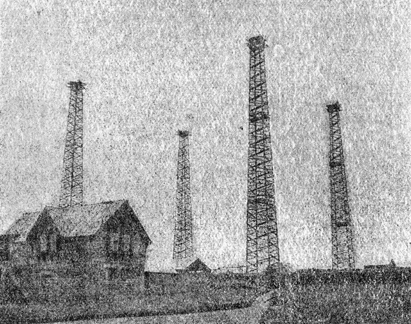
In the initial experiments with this machinery and in its first working there was very considerable risk, owing to its novel and dangerous nature; but throughout the whole of the work from the very beginning, no accident of any kind has taken place, so great have been the precautions taken. The only thing in the nature of a mishap was the collapse of a ring of tall masts, erected in the first place to sustain the aerial wires, but which now have been replaced by four substantial timber towers, 215 feet in height, placed at the corners of a square, 200 feet in length. These four towers sustain a conical arrangement of insulated wires (see Fig. 26) which can be used in sections and which constitute the transmitting radiator or receiver, as the case may be. Each of these wires is 200 feet in length and formed of bare stranded wire.
At the outset, there was much uncertainty as to the effect of the curvature of the earth on the propagation of a Hertzian wave over a distance of many hundreds of miles. In the case of the Atlantic transmission between the station at Poldhu in Cornwall and that at Cape Cod in Massachusetts, U.S.A., we have two stations separated by about 45 degrees of longitude on a great circle, or one-eighth part of the circumference of the world. In this case, the versine of the arc or height of the sea at the half-way point above the straight line or chord joining the two places is 300 miles.
The question has recently attracted the attention of several eminent mathematical physicists. The extent to which a free wave propagated in a medium bends round any object or is diffracted depends on the relation between the length of the wave and the size of the object. Thus, for instance, an object the size of an orange held just in front of the mouth does not perceptibly interfere with the propagation of the waves produced by the speaking or singing voice, because these are from two to six feet in length: but if arrangements are made by means of a Galton whistle to produce air waves half an inch in length, then an obstacle the size of an orange causes a very distinct acoustic shadow. The same thing is true of waves in the ether. The amount of bending of light waves round material objects is exceedingly small, because the average length of light waves is about one-fifty-thousandth part of an inch. In the case of Hertzian wave telegraphy, we are, however, dealing with ether waves many hundreds of feet in length, and the waves sent out from Poldhu have a wave-length of a thousand feet or more, say, one-fifth to one-quarter of a mile. The distance, therefore, between Poldhu and Cape Cod is only at most about twelve thousand wave-lengths, and stands in the same relation to the length of the Hertzian wave used as does a body the diameter of a pea to the wave-length of yellow light. There is unquestionably a large amount of diffraction or bending of the electric wave round the earth, and, proportionately speaking, it is larger than in the case of light waves incident on objects of the same relative size.
Quite recently Mr. H. M. Macdonald (see Proc. Roy. Soc., London, Vol. LXXI., p. 251) has submitted the problem to calculation, and has shown that the power required to send given electric waves 3,000 miles along a meridian of the earth is greater than would be required to send them over the same distance if the sea surface were flat in the ratio of 10 to 3. Hence the rotundity of the earth does introduce a very important reduction factor, although it does not inhibit the transmission. Mr. Macdonald's mathematical argument has, however, been criticised by Lord Rayleigh and by M. H. Poincaré (see Proc. Roy. Soc., Vol. LXXII., p. 40, 1903).
The accomplishment of very long distances by Hertzian wave telegraphy is, however, not merely a question of power, it is also a question of wave-length. Having regard, however, to the possibility that the propagation which takes place in Hertzian wave telegraphy is not that simply of a free wave in space, but the transmission of a semi-loop of electric strain with its feet tethered to the earth, it is quite possible that if it were worth while to make the attempt, an ether disturbance could be made in England sufficiently powerful to be felt in New Zealand.
Leaving, however, these hypothetical questions and matters of pure conjecture, we may consider some of the facts which have resulted from Mr. Marconi's long-distance experiments. One of the most interesting of these is the effect of daylight upon the wave propagation. In one of his voyages across the Atlantic, when receiving signals from Poldhu on board the S.S. Philadelphia, he noticed that the signals were received by night when they could not be detected by day.[72] In these experiments Mr. Marconi instructed his assistants at Poldhu to send signals at a certain rate from 12 to 1 a.m., from 6 to 7 a.m., from 12 to 1 p.m., and from 6 to 7 p.m., Greenwich mean time, every day for a week. He has stated that on board the Philadelphia he did not notice any apparent difference between the signals received in the day and those received at night until after the vessel had reached a distance of 500 statute miles from Poldhu. At distances of over 700 miles, the signals transmitted during the day failed entirely, while those sent at night remained quite strong up to 1,551 miles, and were clearly decipherable up to a distance of 2,099 miles from Poldhu. Mr. Marconi also noted that at distances of over 700 miles, the signals at 6 a.m., in the week between February 23 and March 1, were quite clear and distinct, whereas by 7 a.m. they had become weak almost to total disappearance. This fact led him at first to conclude that the cause of the weakening was due to the action of the daylight upon the transmitting aerial, and that as the sun rose over Poldhu, so the wave energy radiated, diminished, and he suggested as an explanation the known fact of the dissipating action of light upon a negative charge.
Although the facts seem to support this view, another explanation may be suggested. It has been shown by Professor J. J. Thomson that gaseous ions or electrons can absorb the energy of an electric wave, if present in a space through which waves are being transmitted.[73] If it be a fact, as suggested by Professor J. J. Thomson, that the sun is projecting into space streams of electrons, and if these are continually falling in a shower upon the earth, in accordance with the fascinating hypothesis of Professor Arrhenius, then that portion of the earth's atmosphere which is facing the sun will have present in it more electrons or gaseous ions than that portion which is turned towards the dark space, and it will therefore be less transparent to long Hertzian waves.[74] In other words, clear sunlit air, though extremely transparent to light waves, acts as if it were a slightly turbid medium for long Hertzian waves. The dividing line between that portion of the earth's atmosphere which is impregnated with gaseous ions or electrons is not sharply delimited from the part not so illuminated, and there may be, therefore, a considerable penetration of these ions into the regions which I may call the twilight areas. Accordingly, as the earth rotates, a district in which Hertzian waves are being propagated is brought, towards the time of sunrise, into a position in which the atmosphere begins to be ionised, although far from as freely as is the case during the hours of bright sunshine.
Mr. Marconi states that he has found a similar effect between inland stations, signals having been received by him during the night between Poldhu and Poole with an aerial the height of which was not sufficient to receive them by day. It has been found, however, that the effect simply amounts to this, that rather more power is required by day than by night to send signals by Hertzian waves over long distances.
Some interesting observations have also been made by Captain H. B. Jackson, R.N.,[75] on the influence of various states of the atmosphere upon Hertzian wave telegraphy. These experiments were all made between ships of the British Royal Navy, furnished with Hertzian wave telegraphy apparatus on the Marconi system. Some of his observations concerned the effect of the interpositon of land between two ships. He found that the interposition of land containing iron ores reduced the signalling distances, compared with the maximum distance at open sea, to about 30 per cent. of the latter; whilst hard limestone reduced it to nearly 60 per cent. and soft sandstone or shale to 70 per cent. These results show that there is a considerable absorption effect when waves of certain wave-length pass through or over hard rocks containing iron ores. It would be interesting to know, however, whether this reduction was in any degree proportional to the dryness or moisture of the soil. Earth conductivity is far more dependent upon the presence or absence of moisture than upon the particular nature of the material which composes it other than water.
The observations of Captain Jackson, however, only confirm the already well-known fact that Hertzian waves, as employed in the Marconi system of wireless telegraphy, within a certain range of wave-length, are considerably weakened by their passage through land, over land or round land. In some cases he noticed that quite sharp electric shadows were produced by rocky promontories projecting into the line of transmission. His attention was also directed (loc. cit.) to the more important matter of the effect of atmospheric electrical conditions upon the transmission. The effect of all lightning discharges, whether visible or invisible, is to make a record on the telegraphic receiver. On the approach of an atmospheric electrical disturbance towards the receiving station on a ship, the first visible indications generally are the recording of dots at intervals from a few minutes to a few seconds on the telegraphic tape. Captain Jackson states that the most frequent record is that of three dots, the first being separated from the other two by a slight interval like the letters E I on the Morse code, and this is the sign most frequently recorded by distant lightning. But in addition to this, dashes are recorded and irregular signs, which, however, sometimes spell out words in the Morse code. He noted that these disturbances are more frequent in summer and autumn than in winter and spring, and in the neighbourhood of high mountains more than in the open sea. In settled weather, if present, they reach their maximum between 8 p.m. and 10 p.m., and frequently last during the whole of the night, with a minimum of disturbance between 9 a.m. and 1 p.m. Another important matter noted by Captain Jackson is the shorter distance at which signals can usually be received when any electrical disturbances are present in the atmosphere, compared with the distance at which they can be received when none are present. This reduction in signalling distance may vary from 20 to 70 per cent, of that obtainable in fine weather. It does not in any way decrease with the number of lightning flashes, but rather the reverse, the loss in signalling distance generally preceding the first indications on the instrument of the approaching electrical disturbance. It is clear that these observations fit in very well with the theory outlined above, viz., that the atmosphere when impregnated with free electrons or negatively-charged gaseous ions is more opaque to Hertzian waves than when they are absent. Captain Jackson gives an instance of ships whose normal signalling distance was 65 miles, failing to communicate at 22 miles when in the neighbourhood of a region of electrical disturbance. These effects in the case of wireless telegraphy have their parallel in the disturbances caused to telegraphy with wires by earth currents and magnetic storms.
Another effect which he states reduces the usual maximum signaling distance is the presence of material particles held in suspension by the water spherules in moist atmosphere. The effect has been noticed in the Mediterranean Sea when the sirocco wind is blowing. This is a moist wind conveying dust and salt particles from the African coast. A considerable reduction in signalling distance is produced by its advent.
Another interesting observation due to Captain Jackson is the existence of certain zones of weak signals. Thus, for instance, two ships at a certain distance may be communicating well; if their distance increases, the signalling falls off, but is improved again at a still greater distance. He advances an ingenious theory to show that this fact may be due to the interference between two sets of waves sent out by the transmitter having different wave-lengths.
Finally, in the Paper referred to, he emphasises the well-known fact that long-distance signalling can only be accomplished by the aid of an aerial wire and a "good earth." Summing up his results, he concludes: (1) That intervening land of any kind reduces the practical signalling distance between two ships or stations, compared with that which would be obtainable over the open sea, and that this loss in distance varies with the height, thickness, contour, and nature of the land; (2) material particles, such as dust and salt, held in suspension in a moist atmosphere also reduce the signalling distance, probably by dissipating and absorbing the waves; (3) that electrical disturbances in the atmosphere also act most adversely in addition to affecting the receiving instrument and making false signals or strays, as they are called; (4) that with certain forms of transmitting arrangement, interference effects may take place which have the result of creating certain areas of silence very similar to those which are observed in connection with sound signals from a siren.
It is clear, therefore, from all the above observations, that Hertzian-wave telegraphy taking place through the terrestrial atmosphere is not by any means equivalent to the propagation of a wave in free or empty space; and that just as the atmosphere varies in its opacity to rays of light, sometimes being clear and sometimes clouded, so it varies from time to time in transparency to Hertzian waves, the cause of this variation in transparency probably being the presence in the atmosphere of negatively-charged corpuscles or electrons. If there are present in the atmosphere at certain times "clouds of electrons" or "electronic fogs," these may have the effect of producing a certain opacity, or rather diminution in transparency to Hertzian waves, just as water particles do in the case of sunlight.
We may, therefore, in conclusion, review a few of the outstanding problems awaiting solution in connection with Hertzian wave wireless telegraphy. In spite of the fact that this new telegraphy has not been accorded a very hearty welcome by the representatives of official or established telegraphy in Great Britain, it has reached a point, unquestionably owing to Mr. Marconi's energy and inventive power, at which it is bound to continue its progress. But that progress will not be assisted by shutting our eyes to facts. Many problems of great importance remain to be solved. We have not yet reached a complete solution of all the difficulties connected with isolation of stations. In the next place, the question of localising the source of the signals and waves is most important. Our kumascopes and receiving appliances at present are like the rudimentary eyes of the lower organisms, which are probably sensitive to mere differences in light and darkness, but which are not able to see or visualise, in the sense of locating the direction and distance of a radiating or luminous body. Just as we have, as little children, to learn to see, so a similar process has to be accomplished in connection with Hertzian telegraphy, and the accomplishment of this does not seem by any means impossible or even distant. We are dealing with hemispherical waves of electric and magnetic force, which are sent out from a certain radiating centre, and in order to localise that centre we have to determine the position of the plane of the wave and also the curvature of the surface at the receiving point. Something, therefore, equivalent to a range finder in connection with light is necessary to enable us to locate the distance and the direction of the radiant point.
Lastly, there are important improvements possible in connection with the generation of the waves themselves. At the present moment, our mode of generating Hertzian waves involves a dissipation of energy in the form of the light and heat of the spark. Just as in the case of ordinary artificial illuminants, such as lamps of various kinds, we have to manufacture a large amount of ether radiation of long wave length, which is of no use to us for visual purposes—in fact, creating ninety-five per cent, of dark and useless waves for every five per cent. of luminous or useful waves—so in connection with present methods of generating Hertzian waves, we are bound to manufacture by the discharge spark a large amount of light and heat rays which are not wanted, in order to create the Hertzian waves we desire. It is impossible yet to state precisely what is the efficiency, in the ordinary sense of the word, of a Hertzian wave radiator; how much of the energy imparted to the aerial falls back upon it and contributes to the production of the spark, and how much is discharged into the ether in the form of a wave.
Nothing is more remarkable, however, than the small amount of energy which, if properly utilised in electric wave making, will suffice to influence a sensitive receiver at a distance of even one or two hundred miles. Suppose, for instance, that we charge a condenser consisting of a battery of Leyden jars, having a capacity of one seventy-fifth of a microfarad, to a potential of 15,000 volts; the energy stored up in this condenser is then equal to 1·5 joules, or a little more than one foot-pound. If this energy is discharged in the form of a spark five millimetres in length through the primary coil of an oscillation transformer, associated with an aerial 150 feet in height, the circuits being properly tuned by Mr. Marconi's method, then such an aerial will affect, as he has shown, one of Mr. Marconi's receivers, including a nickel silver filings coherer tube, at a distance of over two hundred miles over sea. Consider what this means. The energy stored up in the Leyden jars cannot all be radiated as wave energy by the aerial, probably only half of it is thus radiated. Hence the impartation to the ether at any one locality of about half a foot-pound of energy in the form of a long Hertzian wave is sufficient to affect sensitive receivers situated at any point on the circumference of a circle of 200 miles radius described on the open sea. Hertzian wave telegraphy is sometimes described as being extravagant in power, but, as a matter of fact, the most remarkable thing about it is the small amount of power really involved in conducting it. On the other hand, Hertzian wave manufacture is not altogether a matter of power. It is much more dependent upon the manner in which the ether is struck. Just as half an ounce of dynamite in exploding may make more noise than a ton of gunpowder, because it hits the air more suddenly, so the formation of an effective wave in the ether is better achieved by the right application of a small energy than by the wrong mode of application of a much larger amount. If we translate this fact into the language of electronic theory, it amounts simply to this. It is the electron alone which has a grip of the ether. To create an ether wave, we have to start or stop crowds of electrons very suddenly. If in motion, their motion implies energy, but it is not only their energy which is concerned in the wave making, but the acceleration, positive or negative—i.e., the quickness with which they are started or stopped. It is possible we may discover in time a way of manufacturing long ether waves without the use of an electric spark, but at present we know only one way of doing this—viz., by the discharge of a condenser, and in the discharge of large condensers of very high potentials it is difficult to secure that extreme suddenness of starting the discharge which we can do in the case of smaller capacities and voltages.
How strange it is that the discharge of a Leyden jar studied so profoundly by Franklin, Henry, Faraday, Maxwell, Kelvin and Lodge should have become an electrical engineering appliance of great importance!
Whilst there are many matters connected with the commercial aspect of Hertzian wave telegraphy with which we are not here concerned, there is one on which a word may properly be said. The ability to communicate over long distances by Hertzian waves is now demonstrated beyond question, and even if all difficulties are not overcome at once, it has a field of very practical utility, and may even become of national importance. Under these circumstances, we may consider whether it is absolutely necessary to place the signalling stations so near the coast. The greater facility of transmission over sea has already been discussed and explained, but in time of war, the masts and towers which are essential at present in connection with transmitting stations could be wrecked by shot or shell from an enemy's battleship at a distance of five or six miles out at sea, and would certainly be done within territorial waters. Should not this question receive attention in choosing the location of important signalling stations? For if they can, without prejudice to their use, be placed inland by a distance sufficient to conceal them from sight, their value as a national asset in time of war might be greatly increased.
It has been often contended that whilst cables could be cut in time of war no one can cut the ether; but wireless telegraph stations in exposed situations on high promontories, where they are visible for ten to fifteen miles out at sea and undefended by any forts, could easily be destroyed. The great towers which are essential to carry large aerials are a conspicuous object for ten miles out at sea; and a single well-placed shell from a six-inch gun would wreck the place and put the station completely out of use for many months. Hence if oceanic telegraphy is ever to be conducted in a manner in which the communication will be inviolable or, at any rate, not be capable of interruption by acts of war, the careful selection of the sites for stations is a matter of importance. A small station consisting of a single 150-foot mast and a wooden hut can easily be removed or replaced, but an expensive power station, the mere aerial of which may cost several thousand pounds, is not to be put up in a short time.[76]
Meanwhile, whatever may be the future achievements of this new supermarine wireless telegraphy conducted over long distances, there can be no question as to its enormous utility and present value for intercommunication between ships on the ocean and ships and the shore. At the present time, there are some forty or more of the transatlantic ocean liners and many other ships equipped with this Hertzian wave wireless telegraph apparatus on the Marconi system. Provided with this latest weapon of applied science, they are able to chat with one another, though a hundred miles apart on the ocean, with the ease of guests round a dinner table, to exchange news or make demands for assistance.
Ships that pass in the night, and speak each other in passing— Only a signal shown, and a distant voice in the darkness; So, on the ocean of life, we pass and speak one another, Only a look and a voice, then darkness again, and a silence.
Abundant experience has been gathered to show the inexpressible value of this means of communication in case of accident, and it can hardly be doubted that before long the possession of this apparatus on board every passenger vessel will be demanded by the public, even if not made compulsory. Although the privacy of an ocean voyage may have been somewhat diminished by this utilisation of ether waves, there is a vast compensation in the security that is thereby gained to human life and property by this latest application of the great energies of nature for the use and benefit of mankind.
GEO. TUEKER, PRINTER, SALISBURY COURT, FLEET STREET, LONDON.
Footnotes:
Detailed Transcriber's Notes
The text has been made to match the original text as much as possible retaining all apparent printer's errors and inconsistencies. The following, detail the apparent printer's errors etc. identified in the original text.
Variation in spelling, Strasburg and Strassburg for Strasbourg.
There are a number of inconsistencies in hyphenation present in the original text. Those concerned with the variation between one word or a hyphenated word are detailed below. Those concerned with the variation between multiple words and hyphenated words are too numerous to detail individually.
Inconsistent hyphenation of word, 'anti-node' and 'antinode' both present in original text.
Inconsistent hyphenation of word, 'electro-dynamic' and 'electrodynamic' both present in original text.
Inconsistent hyphenation of word, 'horse-shoe' and 'horseshoe' both present in original text.
Inconsistent hyphenation of word, 'over-blowing' and 'overblowing' both present in original text.
Page 5, possible printer's error, a for at, 'consisting when a rest'.
Page 6, printer's error, comma rather than full stop at end of sentence, 'ether constituting electric radiation,'.
Page 10, printer's error, millmetre for millimetre, 'three thousand volts per millmetre,'.
Page 13, possible printer's error, set for sets, 'there are three set of phenomena'.
Page 13, printer's error, duplicate word, 'detached and and travel away.'.
Page 22, printer's error, correponding for corresponding, 'correponding to this frequency'.
Page 22, printer's error, consist for consists, 'due to Braun, consist of attaching'.
Page 24, printer's error, one-hundreth for one-hundredth, 'capacity of one-hundreth of a microfarad,'.
Page 28, printer's error, missing full stop at end of sentence added, 'in the case of the hammer break.'.
Page 33, printer's error, supppse for suppose, 'Let us supppse'.
Page 46, printer's error, comma rather than full stop at end of sentence, 'to the transmitting aerial,'.
Page 48, possible printer's error, alterations for alternations, 'alterations of electric strain'.
Page 54, printer's error, Banly for Branly, 'proved that in a Banly tube,'.
Page 56, variation in spelling, unsensitive for insensitive, 'wounded and unsensitive.'.
Page 59, possible printer's error, sensive for sensitive 'to work a sensive recording apparatus'.
Page 59, possible printer's error, arragement for arrangement, 'most interesting arragement'.
Page 61, printer's error, missing letter i, 'as shown n Fig. 18,'.
Page 71, printer's error, osciilating for oscillating, 'to that of the osciilating circuit'.
Page 71, printer's error, impluse for impulse, 'the period of that impluse'.
Page 74, possible printer's error, extra comma in date, 'on May, 17, 1901.'.
Page 76, printer's error, arangements for arrangements, 'variation of the above arangements'.
Page 77, printer's error, systonic for syntonic, 'the systonic transmitting'.
Page 86, printer's error, interpositon for interposition, 'effect of the interpositon of land'.
Page 87, printer's error, signaling for signalling, 'the usual maximum signaling'.