Front matter (continued 2)
Reading edition
In the induction coil, the electromotive force generated in the secondary coil at the "break" of the primary current is higher than that at the "make," and this electromotive force, other things being equal, depends upon the rate at which the magnetism of the iron core dies away, and its duration is shorter in proportion as the whole time occupied in the disappearance of the magnetism is less. The Wehnelt break does not increase the actual secondary electromotive force, nor apparently its duration, but it greatly increases the number of times per second this electromotive force makes it appearance. Hence this break increases the current, but not the electromotive force in the secondary coil. It, therefore, does not assist us in the direction required—viz., in prolonging the duration of the secondary electromotive force to enable larger capacities to be charged.
The important point in connection with the working of a coil used for charging a condenser is not the length of spark which the coil can give alone, but the length of spark which can be obtained between small balls attached to the secondary terminals, when these terminals are also connected to the two surfaces of the condenser. Thus, a coil may give a ten-inch spark if worked alone, but on a capacity of one-thirtieth of a microfarad it may not be able to give more than a five-millimetre spark. Hence, in describing the value of a coil for wireless telegraph purposes, it is not the least use to state the length of spark which the coil will give between the pointed conductors in air, but we must know the spark length which it will give between brass balls, say, 1 centimetre in diameter, connected to the secondary terminals, when these terminals are also short-circuited by a stated capacity, the spark not exceeding that length at which it becomes non-oscillatory.
A good way of describing the value of an induction coil for wireless telegraph purposes is to state the length of oscillatory spark which can be produced between balls one centimetre in diameter connected to the secondary terminals, when these balls are short-circuited by a condenser having a capacity, say, of one-hundredth of a microfarad, and also one-tenth of a microfarad.
If a hammer or motor interrupter is employed with the coil, then a primary condenser must be connected across the points between which the primary circuit is broken. This condenser generally consists of sheets of tinfoil alternated with sheets of paraffin paper, and for a ten-inch coil may have a capacity of about 0·4 or 0·5 of a microfarad.[15]
Lord Rayleigh discovered that if the interruption of the primary circuit is sufficiently sudden and complete, as when the primary circuit is severed by a bullet from a gun, the primary condenser can be removed and yet the sparks obtained from the secondary circuit are actually longer than those obtained with the condenser and the ordinary break.[16]
In the use, however, of the coil for Hertzian wave telegraphy, with all interrupters except the Wehnelt break a condenser of suitable capacity must be joined across the break points.
Turning in the next place to the primary key, or signalling interrupter, it is necessary to be able to control the torrent of sparks between the secondary terminals of the coil, and to cut them up into long and short periods in accordance with the letters of the Morse alphabet. This is done by means of the primary key. The primary key generally consists of an ordinary massive single contact key with heavy platinum contacts. As the current to be interrupted amounts to about ten amperes and is flowing in a highly inductive circuit, the spark at break is considerable. If the attempt is made to extinguish this spark by making the contacts move rapidly away from one another through a long distance, in other words, by using a key with a wide movement, then the speed at which the signals can be set is greatly diminished. The speed of sending greatly depends upon the time taken to move the key up and down between sending two dots, and hence a short range key sends quicker than a long range key. If it is desired to use a short range key, then some method must be employed to extinguish the spark at the contacts. This is done in one of three ways: Either by using a high resistance coil to short-circuit these contacts, or by a condenser, or by a magnetic blow-out, as in the case of an electric tramcar circuit controller. Of these, the magnetic blow-out is probably the best.
Mr. Marconi has designed a signalling key which performs the function not only of interrupting the primary circuit, but at the same time breaks connection between the receiving appliance and the aerial.
The author has designed for signalling purposes a multiple contact key which interrupts the circuit simultaneously in ten or twelve different places. The particular point about this break is the means which are taken to make the twelve interruptions absolutely simultaneous. If these interruptions are not simultaneous, the spark always takes place at the contact which is broken first, but if the circuit is interrupted in a dozen places quite simultaneously, then the spark is cut up into a dozen different portions, and the spark at each contact is very much diminished. By this break, voltages up to two thousand volts may be quite easily dealt with.
Various forms of break have been devised in which the circuit is broken under oil or insulating fluids, but, generally speaking, these devices are not very portable, and a dry contact between platinum surfaces with appropriate means for cutting up the spark and blowing it out so that the mechanical movement of the switch may be small is the best thing to use.
The signalling key is really a very important part of the transmitting arrangement, because whatever may be the improvements in receiving instruments, it is not possible to receive faster than we can send. A great many statements have appeared in the daily papers as to the possibility of receiving hundreds of words a minute by Hertzian wave telegraphy, but the fact remains that whatever may be the sensibility of the receiving appliance, the rate at which telegraphy of any kind can be conducted is essentially dependent upon the rate at which the signals can be sent, and this in turn is largely dependent upon the mechanical movement which the key has to make to interrupt the primary circuit, and so interrupt the secondary discharge.
In order to make the separation of the contact points of the switch as small as possible, and yet prevent an arc being established, various blow-out devices have been employed. The simplest arrangement for this purpose is a powerful permanent magnet so placed that its inter-polar field embraces the contact points and is at right angles to them.
As already explained, the applicability of the induction coil in wireless telegraphy is limited by the fact of the high resistance of the secondary circuit and the small current that can be supplied from it. Data are yet wanting to show what is the precise efficiency of the induction coil, as used in Hertzian wave telegraphy, but there are reasons for believing that it does not exceed 50 or 60 per cent.
Where large condensers have to be charged—in other words, where we have to deal with larger powers—we are obliged to discard the induction coil and to employ the alternating-current transformer. But this introduces us to a new class of difficulties. If an alternating-current transformer wound for a secondary voltage, say, of 20,000 or 30,000 volts, has its primary circuit connected to an alternator, then if the secondary terminals, to which are connected two spark balls, are gradually brought within striking distance of one another, the moment we do this an alternating-current arc starts between these balls. If the transformer is a small one, there is no difficulty in extinguishing this arc by withdrawing the secondary terminals, but if the transformer is a large one, say, of ten or twenty kilowatts, dangerous effects are apt to ensue when such an experiment is tried. The short circuiting of the secondary circuit almost entirely annuls the inductance of the primary circuit. There is, therefore, a rush of current into the transformer, and if it is connected to an alternator of low armature resistance the fuses are generally blown and other damage done.
Let us supppse, then, that the secondary terminals of the transformer are also connected to a condenser. On bringing together the spark balls connected with the secondary terminals we may have one or more oscillatory discharges, but the process will not be continuous, because the moment that the alternating-current arc starts between the spark balls it reduces their difference of potential to a comparatively low value, and hence the charge taken by the condenser is very small, and, moreover, the circuit is not interrupted periodically so as to re-start a train of oscillations.
When, therefore, we desire to employ an alternating-current transformer as a source of electromotive force, although it may have the advantage that the resistance of the secondary circuit of the transformer is generally small compared with that of the secondary circuit of an induction coil, yet, nevertheless, we are confronted with two practical difficulties: (1) How to control the primary current flowing into the transformer, and (2) how to destroy the alternating-current arc between the spark balls and reduce the discharge entirely to the disruptive or oscillatory discharge of the condenser.
The control over the current can be obtained, in accordance with a plan suggested by the author, by inserting in the primary circuit of the transformer two variable choking coils. The form in which it is preferred to construct these is that of a cylindrical bobbin standing upon a laminated cross-piece of iron. These bobbins can have let down into them an E-shaped piece of laminated iron, so as to complete the magnetic circuit, and thus raise the inductance of the bobbin. By placing two of these variable choking coils in series with the primary circuit, the current is under perfect control. We can fix a minimum value below which the current shall not fall, by adjusting the position of the cores of these two choking coils, and we can then cause that current to be increased up to a certain limit which it cannot exceed, by short-circuiting one of these choking coils by an appropriate switch. Several ways have been suggested for extinguishing the alternating current arc which forms between the spark balls connected to the secondary terminals when these are brought within a certain distance of one another. One of these is due to Mr. Tesla. He places a strong electromagnet so that its lines of magnetic flux pass transversely between the spark balls. When the discharge takes place the electric arc is blown out, but if the balls are short-circuited by a condenser the oscillatory discharge of the condenser still takes place across the spark gap. Professor Elihu Thomson achieves the same result by employing a blast of air thrown on the spark gap. This has the effect of destroying the alternating-current arc, but still leaves the oscillating discharge of the condenser. The action is somewhat tedious to explain in words, but it can easily be understood that the blast of air, by continually breaking down the alternating-current arc which tends to form, allows the condenser connected to the spark balls to become charged with the potential of the secondary circuit of the transformer, and that this condenser then discharges across the spark gap, producing an oscillatory discharge in the usual manner. The author has found that, without the use of any air blast or electromagnet, simple adjustment of the double choking coil in the primary circuit of the transformer, as above described, is sufficient to bring about the desired result, when the capacity of the condenser is adjusted to be in resonance.
Another method, which has been adopted by M. d'Arsonval, is to cause the spark to pass between two balls placed at the extremities of metal rods, which are in rapid rotation like the spokes of a wheel. In this case, the draught of air produced by the passage of the spark balls blows out the arc and performs the same function as the blast of air in Professor Elihu Thomson's method. When these adjustments are properly made, it is possible, by means of a condenser and an alternating-current transformer supplied with current from an alternator, to create a rapidly intermittent oscillatory discharge, the sparks of which succeed one another so quickly that it appears almost continuous. When using a large transformer and condenser, the noise and brilliancy of these sparks are almost unbearable, and the eyes may be injured by looking at this spark for more than a moment. In the construction of transformers intended to be used in this manner, very special precautions have to be taken in the insulation of the primary and secondary circuits, and the insulation of these from the core.
It may be remarked in passing that experimenting with large high-tension transformers coupled to condensers of large capacity is exceedingly dangerous work, and the greatest precautions are necessary to avoid accident. In the light, however, of sufficient experience there is no difficulty in employing high-tension transformers in the above-described manner, and in obtaining electromotive forces of upwards of a hundred thousand volts supplied through transformers capable of yielding any required amount of current.
On occasions where continuous current alone is available, a motor generator has to be employed converting the continuous current into an alternating current. This is best achieved by the employment of a small alternator directly coupled to a continuous-current motor; or by providing the shaft of a continuous-current motor with two rings connected to two opposite portions of its armature, so that when continuous current is supplied to the brushes pressing against the commutator, an alternating current can be drawn off from two other brushes touching the above-mentioned insulated rings.
The next element of importance in the transmitting arrangement is the spark gap. In the case of those transmitters employing an ordinary induction coil, the secondary spark, or the discharge of any condenser connected to the secondary terminals can be taken between the brass balls about half an inch or one inch in diameter, with which the terminals of the secondary coil are usually furnished; and it is generally the custom to allow this spark discharge to take place in air at ordinary pressure. In the very early days of his work Mr. Marconi adopted the discharger devised by Professor Rhigi, in which the spark takes place between two brass balls placed in vaseline or other highly insulating oil.[17] But whatever advantage may accrue from using oil as the dielectric in which the spark discharge takes place, when carrying out simple laboratory experiments on Hertzian waves, there is no advantage in the case of wireless telegraphy. The Rhigi discharger was, therefore, soon discarded. If discharges having large quantity are passed through oil, it is rapidly decomposed or charred, and ceases to retain the special insulating and self-restoring character which is necessary in the medium in which an oscillating spark is formed. The conditions when the discharges of large condensers are passed between spark balls are entirely different from those when the quantity of the spark, or to put it in more exact language, the current passing, is very small. In the case of Hertzian experiments it is necessary, as shown by Hertz, to maintain a high state of polish on the spark balls when they are employed for the production of short waves of small energy, but when we are dealing with large quantities of energy at each discharge, those methods which succeed for laboratory experiments are perfectly impracticable. The conditions necessary to be fulfilled by a discharger for use in Hertzian wave telegraphy are that the surfaces shall maintain a constant condition and not be fused or eaten away by the spark, and, next, that the medium in which the discharge takes place shall not be decomposed by the passage of the spark, but shall maintain the property of giving way suddenly when a certain critical pressure is reached, and passing instantly from a condition in which it is a very perfect insulator to one in which it is a very good conductor; and, thirdly, that on the cessation of the discharge, the medium shall immediately restore itself to its original condition.
When using the ordinary ten-inch induction coil, and when the capacity charged by it does not exceed a small fraction of a microfarad, it is quite sufficient to employ brass or steel balls separated by a certain distance in air, at the ordinary pressure, as the arrangement of the discharger. When, however, we come to deal with the discharges of very large condensers, at high electromotive forces, then it is necessary to have special arrangements to prevent the destruction of the surfaces between which the spark passes, or their continual alteration, and many devices have been invented for this purpose. The author has devised an arrangement which fulfils the above conditions very perfectly for use in large power stations, but the details of this cannot be made public at the present time.
We have to consider in connection with this part of the subject the dielectric strength of air under different pressures and for different thicknesses. It was shown by Lord Kelvin, in 1860, that the dielectric strength of very thin layers of air is greater than that of thick layers.[18] The electric force, reckoned in volts per centimetre, required to pierce a thickness of air from two to ten millimetres in thickness, at atmospheric pressure, may be taken at 30,000 volts per centimetre. The same force in electrostatic units is represented by the number 100, since a gradient of 300 volts per centimetre corresponds to a force of one electrostatic unit. It appears also that for air and other gases there is a certain minimum voltage (approximately 400 volts) below which no discharge takes place, however near the conducting surfaces may be approximated. In this particular practical application, however, we are only concerned with spark lengths which are measured in millimetres or centimetres, lying, say, between one or two millimetres and five or six centimetres. Over this range of spark length we shall not generally be wrong in reckoning the voltage required to produce a spark between metal balls in air at the ordinary pressure to be given by the rule:

If, however, the air pressure is increased above the normal by including the spark balls in a vessel in which air can be compressed, then the spark length, corresponding to a given potential difference, very rapidly decreases. Mr. F. J. Jervis-Smith[19] found that by increasing the air pressure from one atmosphere to two atmospheres round a pair of spark balls he reduced the spark length given by a certain voltage from 2·5 to 0·75 centimetre.
Professor R. A. Fessenden has also made some interesting observations on the effect of using compressed air round spark gaps. He found that if a certain voltage between metal surfaces would yield a spark four inches in length, at the ordinary pressure of the air, if the spark balls were enclosed in a cylinder, the air round them compressed at 50lb. per square inch, the spark length for the same potential difference of the balls was only one quarter of an inch, or one-sixteenth of its former value.
The writer has also made experiments with an apparatus designed to study the effect of compressed air round the spark gap. The experimental arrangements are as follows: A ten-inch induction coil has one of its terminals connected to the internal coating of a battery of Leyden jars. The external coating is connected through the primary coil of an oscillation transformer with the other secondary terminal of the coil, and these secondary terminals are also connected to a spark gap consisting of two brass balls enclosed in a glass vessel into which air can be forced by a pump, the air pressure being measured by a gauge. The balls in the glass vessel are set at a distance of about three millimetres apart. The secondary circuit of the oscillation transformer is connected to another pair of spark balls, the distance of which can be varied.
Suppose we begin with the air in the glass vessel containing the balls connected to the secondary terminals of the induction coil, which may be called the secondary balls, at atmospheric pressure, and create oscillatory discharges in the primary coil of the oscillation transformer, we have a spark between the balls, which may be called the tertiary balls, connected to the secondary terminals of the oscillation transformer. If the secondary balls are placed, say, three millimetres apart, the air in the glass vessel enclosing them being at the ordinary atmospheric pressure, then with one particular arrangement of jars used, a spark twenty-five or twenty-six millimetres long between the tertiary balls will take place. Suppose, then, we increase the pressure of the air round the secondary balls, pumping it by degrees to 10, 20, 30, 40 and 50lb. per square inch above the atmospheric pressure. We find that the spark between the tertiary balls will gradually leap a greater and greater distance, and when the pressure of the air is 50lb. per square inch, we can obtain a fifty-millimetre spark between the tertiary balls, whereas when the air in the glass vessel is at atmospheric pressure, we can only obtain a spark between the tertiary balls of half that length.
This experiment demonstrates that the effect of compressing the air round the secondary terminals of the induction coil is to greatly increase the difference of potential between these balls before the spark passes. In fact, it requires about double the voltage to force a spark of the same length through air compressed at 50lb. on the square inch that it does to make a spark of identical length between the same balls in air at normal pressure. This shows that there is a very great advantage in taking the discharge spark in compressed air. A better effect can be produced by substituting dry gaseous hydrochloric acid for air at ordinary pressures.
One other incidental advantage is that the noise of the spark is very much reduced. The continual crackle, of the discharge spark of the induction coil in connection with wireless telegraphy is very annoying to sensitive ears, but in this manner we can render it perfectly silent.
Professor Fessenden also states that when the spark balls are surrounded by compressed air, and if one of the balls is connected with a radiator, the compression of the air, although it shortens the spark-gap corresponding to a given voltage, does not in any way increase the radiation. When, however, the air in the spark-ball vessel is compressed to 60lb. in the square inch, there is a marked increase in the effective radiation, and at 80lb. per square inch the energy emitted in the form of waves is nearly three and a-half times greater than at 50lb., the potential difference between the balls remaining the same.
This effect is no doubt connected with the fact that the production of a wave, whether in ether or in any other material, is not so much dependent upon the absolute force applied as upon the suddenness of its application. To translate it into the language of the electronic theory, we may say that the electron radiates only whilst it is being accelerated, and that its radiating power, therefore, depends not so much upon its motion as upon the rate at which its motion is changing.
The advantage in using compressed air round the spark gap is that we can increase the effective potential difference between the balls without rendering the spark non-oscillatory. In air of the ordinary pressure there is a certain well-defined limit of spark length for each voltage, beyond which the discharge becomes non-oscillatory, but by the employment of spark balls in compressed air, we can increase the potential difference between the balls corresponding to a given distance apart before a discharge takes place, or employ higher potentials with the same length of spark gap. In addition to this, we have, perhaps, the production of a more effective radiation, as asserted by Fessenden, when the air pressure exceeds a certain critical value.
The next element which we have to consider in the transmitting arrangements is a condenser of some kind for storing the energy which is radiated at intervals. Where a condenser other than the aerial is employed for storing the electric energy which is to be radiated by the aerial, some form of it must be constructed which will withstand high potentials. As the dielectric for such a condenser, only two materials seem to be of any practical use, viz., glass and micanite. Glass condensers in the form of Leyden jars have been extensively employed, but they have the disadvantage that they are very bulky in proportion to their electrical capacity. The instrument maker's quart Leyden jar has a capacity of about one-five hundredth of a microfarad, but it occupies about 150 cubic inches or more. Professor Braun has employed in his transmitting arrangements condensers consisting of small glass tubes like test tubes, lined on the inside and outside with tinfoil, which are more economical in space. The author has found that condensers for this purpose are best made of sheet glass about one-eighth or one-tenth of an inch in thickness, coated to within one inch of their edge on both sides with tinfoil, and arranged in a vessel containing resin or linseed oil, like the plates of a storage battery. M. d'Arsonval has employed micanite, but although this material has a considerably higher dielectric strength than glass, it is much more expensive to obtain a given capacity by means of micanite than by glass, although the bulk of the condenser for a given capacity is less.
To store up a certain amount of electric energy in a condenser, we require a certain definite volume of dielectric, no matter how we may arrange it, and the volume required per unit of energy is determined by the dielectric strength of the material. Thus, for instance, ordinary sheet glass cannot be safely employed with a greater electric force than is represented by 20,000 volts for one-tenth of an inch in thickness, or, say, a potential gradient of 160,000 volts per centimetre. This is equivalent to an electric force of about 500 electrostatic units. This may be called the safe-working force. The electrostatic capacity of a condenser formed of two metal surfaces a foot square separated by glass three millimetres in thickness is between 1/360 and 1/400 of a microfarad. If this condenser is charged to 20,000 volts, we have stored up in it half a joule of electric energy, and the volume of the dielectric is 270 cubic centimetres. Hence, to store up in a glass condenser electric energy represented by one joule at a pressure of 20,000 volts, we require 500 cubic centimetres of glass, and it will be found that if we double the pressure and double the thickness of the glass, we still require the same volume.[20] Hence, in the construction of high-tension condensers to store up a given amount of energy, the economical problem is how to obtain the greatest energy-storing capacity for the least money. Glass fulfils this condition better than any other material. Although some materials may have very high dielectric strength, such as paper saturated with various oils, or resins, yet they cannot be used for the purpose of making condensers to yield oscillatory discharges, because the oscillations are damped out of existence too soon by the dielectric.
In arranging condensers to attain a given capacity, regard has to be taken of the fact that for a given potential difference there must be a certain total thickness of dielectric, and that if condensers of equal size are being arranged in parallel it adds to their capacity, whilst joining them in series divides their capacity. If N equal condensers or Leyden jars have each a capacity represented by C, and if they are joined n in series and m in parallel, the joint capacity of the whole number is mC/n, where the product mn = N.
Passing on next to the consideration of oscillation transformers of various kinds—these are appliances of the nature of induction coils for transforming the current or electromotive force of electrical oscillations in a required ratio. These coils are, however, destitute of any iron core, and they generally consist of coils of wire wound on a fibre, wooden or ebonite frame, and must be immersed in a vat of oil to preserve the necessary insulation. No dry insulation of the nature of indiarubber or gutta-percha will withstand the high pressures that are brought to bear upon the circuits of an oscillation transformer. In constructing these transformers we have to set aside all previous notions gathered from the design of low-frequency iron-core transformers. The chief difficulty we have to contend against in the construction of an effective oscillation transformer is the inductance of the primary circuit and the magnetic leakage that takes place. In other words, the failure of the whole of the flux generated by the primary circuit to pass through or be linked with the secondary circuit. Mr. Marconi has employed an excellent form of oscillation transformer, in the design of which he was guided by a large amount of experience. In this transformer the two circuits are wound round a square wooden frame. The primary circuit consists of a number of strands of thick insulated cable laid on in parallel, so that it consists of only one turn of a stranded conductor. The secondary circuit consists of a number of turns, say, ten to twenty, of thinner insulated wire laid over the primary circuit and close to it, so that the transformer has the transformation ratio of one to ten or one to twenty. In the arrangements devised and patented by Mr. Marconi, these two circuits, with their respective capacities in series with them, are tuned to one another, so that the time-period of each circuit is exactly the same, and without this tuning the device becomes ineffective as a transformer.[21] There is no advantage in putting a number of turns on the primary circuit, because such multiplication simply increases the inductance, and, therefore, diminishes the primary current in the same ratio which it multiplies the turns, and hence the magnetic field due to the primary circuit remains the same. Where it is desired to put a number of turns upon a coil, and yet at the same time keep the inductance down, the writer has adopted the device of winding a silk or hemp rope well paraffined between the turns of the circuit, so as to keep them further apart from one another, and as the inductance depends on the turns per centimetre, this has the effect of reducing the inductance.
The next and most important element in any transmitting station is the aerial or radiator, and it was the introduction of this element by Mr. Marconi which laid the foundation for Hertzian wave telegraphy as opposed to mere experiments with the Hertzian waves. We may consider the different varieties of aerial which have been evolved from the fundamental idea. The simple single Marconi aerial consists of a bare or insulated wire, generally about 100ft. or 150ft. in length, suspended from a sprit attached to a tall mast. As these masts have generally to be erected in exposed positions, considerable care has to be taken in erecting them with a large margin of strength. To the end of a sprit is attached an insulator of some kind, which may be a simple ebonite rod, or sometimes a more elaborate arrangement of oil insulators, and to the lower end of this insulator is attached the aerial wire. As at the top of the aerial we have to deal with potentials capable sometimes of giving sparks several feet in length, the insulation of the upper end of the aerial is an important matter.
In the original Marconi system, the lower end of the aerial was simply attached to one spark ball connected to one terminal of the induction coil, and the other terminal and spark ball were connected to the earth. In this arrangement, the aerial acted not only as radiator, but as energy-storing capacity, and as already explained, its radiating power was on that account limited. The earth connection is an important matter. For long distance work, a good earth is essential. This earth must be made by embedding a metal plate in the soil, and many persons are under the impression that the efficiency of the earth plate depends upon its area, but this is not the fact. It depends much more upon its shape, and principally upon the amount of its "edge." It has been shown by Professor A. Tanakadate, of Japan, that if a metal plate of negligible resistance is embedded in an infinite medium having a resistivity r, the electrical conductance of this plate is equal to times the electrostatic capacity of the same plate placed in a dielectric of infinite extent. Hence in designing an earth plate, we have to consider not how to give it the utmost amount of surface, but how to give it the greatest electrostatic capacity, and for this purpose it is far better to divide a given amount of metal into long strips radiating out in different directions, rather than to employ it in the form of one big square or circular plate. The importance of the "good earth" will have been seen from our discussion on the mode of formation of electric waves. There must be a perfectly free access for the electrons to pass into and out of the aerial. Hence, if the soil is dry, or badly conductive in the neighbourhood, we have to go down to a level at which we get a good moist earth. In fact, the precautions which have to be taken in making a good earth for Hertzian wave telegraphy are exactly those which should be taken in making a good earth for a lightning conductor.

Whilst on the subject of aerials, a word may be said on the localisation of wireless telegraph stations on the Marconi system. For reasons which were explained previously, the transmission of signals is effected more easily over water than over dry land, and it is hindered if the soil in the neighbourhood of the sending station is a poor conductor. Hence, all active Hertzian wave telegraph stations, like all active volcanoes, are generally found near the sea. In those cases in which a multiple aerial has to be put up consisting of many wires, one mast may be insufficient to support the structure, and several masts arranged in the form of a square or a circle have to be employed. The illustrated papers have reproduced numerous pictures of the Marconi power stations at Poldhu in Cornwall, Glace Bay in Nova Scotia, and Cape Cod in the United States. In these stations, after preliminary failures to obtain the necessary structural strength with ordinary masts, tall lattice girder wooden towers have been built, about 215 feet in height, well stayed against wind pressure, and which so far have proved themselves capable of withstanding any storm of wind which has come against them.
An important question in connection with the sending power of an aerial is that of the relation of its height to the distance covered. Some time ago Mr. Marconi enunciated a law, as the result of his experiments, connecting these two quantities, which may be called Marconi's Law. He stated that the height of the aerial to cover a given distance, other things remaining the same, varies as the square root of the distance. Let D be the distance and let L be the length of the aerial, then if both the transmitting and receiving aerial are the same height, we may say that D varies as L2. This relation may be theoretically deduced as follows:—Any given receiving apparatus for Hertzian wave telegraphy requires a certain minimum energy to be imparted to it to make it yield a signal. If the resistance and the capacity of the receiver is taken as constant, this minimum working energy is proportional to the square of the electromotive force set up in the receiving aerial by the impact on it of the electric waves. This electromotive force varies as the length of the receiving aerial and as the magnetic force due to the wave cutting across it, and the magnetic force varies as the current in the transmitting aerial, and therefore, for any given voltage varies as the capacity, and therefore as the length of the transmitting aerial. If, therefore, the transmitting and receiving aerial have the same length, the minimum energy varies as the square of the electromotive force in the receiving aerial, and therefore as the fourth power of the length of either aerial, since the electromotive force varies as the product of the lengths of the aerials. Hence, when the distance between the aerials is constant, the minimum working energy varies as the fourth power of the height of either aerial, but when the lengths of the aerials are constant, the energy caught up by the receiving aerial must vary inversely as the square of the distance D between the aerials. Hence, if we call e this minimum working energy, e must vary as 1/D2 when L is constant, or as L4 when D is constant, and since e is a constant quantity for any given arrangements of receiver and transmitter, it follows that when the height of aerial and distance vary, the ratio L4/D2 is constant, or, in other words, D2 varies as L4 or D varies as L2—i.e., distance varies as the square of the height of the aerial, which is Marconi's Law. The curve, therefore, connecting height of aerial with sending distance for given arrangements is a portion of a parabola.
Otherwise, the law may be stated in the form , where a is a numerical coefficient. If L and D are both measured in metres, then, for recent Marconi apparatus as used on ships, a=0·15 roughly. (See a report on experiments made for the Italian Navy, 1900-1901, by Captain Quintino Bonomo—"Telegrafia senza fili," Rome, 1902.)

This law, however, must not be used without discretion. After Mr. Marconi had transmitted signals across the British Channel, some people, forgetting that a little knowledge is a dangerous thing, predicted that aerials a thousand feet in height would be required to signal across the Atlantic, but Mr. Marconi has made such improvements of late years in the receiving arrangements that he has been able to receive signals over three thousand miles in 1903 with aerials only thirty-three per cent. longer than those which, in 1899, he employed to cover twenty miles across the English Channel.
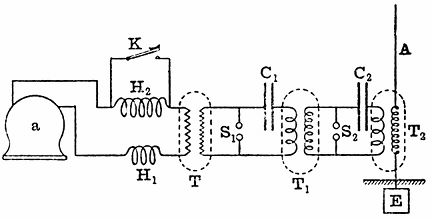
Fig. 15.—Alternating-current Double-transformation Power Plant for Generating Electric Waves (Fleming). a, alternator; H1H2, choking coil; K, signalling key; T, step-up transformer; S1S2 spark-gap; C1C2 condensers; T1T2, oscillation transformers; A, aerial; E, earthplate.
We turn, in the next place, to the consideration of those devices for putting more power into the aerial than can be achieved when the aerial itself is simply employed as the reservoir of energy. Professor Braun, of Strassburg, in 1899, described a method for doing this by inducing oscillations in the aerial by means of an oscillation transformer, these oscillations being set up by the discharges from a Leyden jar or battery of Leyden jars, which formed the reservoir of energy. The induction coil is employed to produce a rapidly intermittent series of electrical oscillations in the primary coil of an oscillation transformer by the discharge through it of a Leyden jar. Mr. Marconi immensely improved this arrangement, as described by him in a lecture given before the Society of Arts on May 17, 1901, by syntonising the two circuits and making the circuit, consisting of the capacity of the aerial and the inductance of the secondary circuit of the oscillation transformer, have the same time-period as the circuit consisting of the Leyden jars, or energy-storing condenser, and the primary circuit of the oscillation transformer, and by so doing immensely added to the power and range of the apparatus.
Starting from these inventions of Braun and Marconi, the author devised a double transmission system in which the oscillations are twice transformed before being generated in the aerial, each time with a multiplication of electromotive force and a multiplication of the number of groups of oscillations per second. This arrangement can best be understood from the diagram (see Fig. 15).
In this case a transformer, T, or transformers receive alternating low-frequency current from an alternator, a, being regulated by passing through two variable choking coils, H1 and H2, so as to control it. This alternating current is transformed up from a potential of two thousand to twenty, forty or a hundred thousand, and is employed to charge a large condenser, C1, which discharges across a primary spark-gap, S1, through the primary coil of an oscillation transformer, T1. The secondary circuit of the oscillation transformer is connected to a second pair of spark balls, S2, which in turn are connected by a secondary condenser, C2, and the primary circuit of a third transformer, T2 and the secondary circuit of this last transformer are inserted between a Marconi aerial, A, and the earth E. When all these circuits are tuned to resonance by Mr. Marconi's methods, we have an enormously powerful arrangement for creating electric waves, or rather trains of electric waves, sent out from the aerial, and the oscillations are controlled and the signals made by short-circuiting one of the choking coils.
Another transmitting arrangement, which involves a slightly different principle, and employs no oscillation transformer, is one due also to Professor Braun. In this case, a condenser and inductance are connected in series to the spark balls of an induction coil, and oscillations are set up in this circuit. Accordingly, there are rapid fluctuations of potential at one terminal of the condenser. If to this we connect a long aerial, the length of which has been adjusted to be one quarter of the length of wave corresponding to the frequency, in other words, to make it a quarter-wave resonator, then powerful oscillations will be accumulated in this rod. The relation between the height (H) of the aerial and the frequency is given by the equation 3 × 1010=4nH, where n is the frequency of the oscillations and H the height of the aerial in centimetres. The frequency of the oscillations is determined by the capacity (C) and inductance (L) of the condenser circuit, and can be calculated from the formula

That is, the frequency is obtained by dividing into the number 5,000,000, the square root of the product of the capacity in microfarads, and inductance in centimetres, of the condenser circuit. It will be found, on applying these rules, that it is impossible to unite together any aerial of a length obtainable in practice with a condenser circuit of more than a very moderate capacity. It has been shown that for an aerial two hundred feet in height the corresponding resonating frequency is about one and a quarter million.[22] As we are limited in the amount to which we can reduce the inductance of a discharge circuit, probably to something like a thousand centimetres, a simple calculation shows that the largest capacity we can employ is about a sixtieth of a microfarad. This capacity, even if charged at 60,000 volts, would only contain thirty joules of energy, or about 22·5 foot-pounds, which is a small storage compared to that which can be achieved when we are employing the above-described methods, which involve the use of an oscillation transformer. In such a case, however, it is an advantage to employ a spark-gap in compressed air, because we can then raise the voltage to a much higher value than in air of ordinary pressure without lengthening the spark so much as to render it non-oscillatory.
When employing methods involving the use of an oscillation transformer, it is possible to use multiple aerials having large capacity, and hence to store up a very large amount of energy in the aerial, which is liberated at each discharge. The most effective arrangement is one in which the radiator draws off gradually a large supply of energy from a non-radiating circuit, and so sends out a true train of waves, and not mere impulses, into the ether, and as we shall see later on, it is only when the radiation takes place in the form of true wave trains that anything like syntony can be obtained.
There are a number of variants of the above methods of arranging the radiator and associated energy-storing in circuit. Descriptions of these arrangements will be found in patents by Mr. Marconi, Professor Slaby and Count von Arco, Sir Oliver Lodge, Dr. Muirhead, Professor Popoff, Professor Fessenden and others. In all cases, however, they are variations of the three simple forms of radiator already described.
Returning to the analogy with the air or steam siren suggested at the commencement of this article, the reader will see in the light of the explanations already given, that all parts of the air-wave producing apparatus have their analogues in the electrical radiator as used in Hertzian wave telegraphy. The object in the one case is to produce rapid oscillations of air particles in a tube, which result in the production of an air wave in external space; in the other case, the arrangement serves to produce oscillations of electrons or electrical particles in a wire, the movements of which create a disturbance in the ether called an electrical wave. Comparing together, item by item, it will be seen, therefore, that the induction coil or transformer used in connection with electric-wave apparatus is analogous to the air pump in the siren plant. In the electrical apparatus, this electron pump is employed to put an electrical charge into a condenser; in the air wave apparatus, the air pump is employed to charge an air vessel with high pressure air. From the electrical condenser the charge is released in the form of a series of electrical oscillations, and in the air wave producing appliance, the compressed air is released in the form of a series of intermittent puffs or blasts. In the electrical wave producing apparatus, these electrical oscillations in the condenser circuit are finally made to produce other oscillations in an air wire or open circuit, just as the puffs of air finally expend themselves in producing aerial oscillations in the siren tube. Finally, in the one case we have a series of air waves and in the other case, a series of electrical waves. These trains of electric waves or air waves, as the case may be, are intermitted into long and short groups, in accordance with the signals of the Morse alphabet, and, therefore, the Hertzian wave transmitter, in whatever form it may be employed, when operated by means of a Marconi aerial, is in fact an electrical siren apparatus, the function of which is to create periodic disturbances in the universal ether of the same character as those which the siren produces in atmospheric air.
We have to consider in the next place the arrangements of the receiving station and the various forms of receivers that have been devised for effecting telegraphy by Hertzian waves. Just as the transmitting station consists essentially of two parts, viz., a part for creating electrical oscillations and a part for throwing out or radiating electric waves, so the receiving-station appliances may be divided into two portions; the function of one being to catch up a portion of the energy of the passing wave, and that of the other to make a record or intelligible signal in some manner in the form of an audible or visible sign.
Accordingly, there must be at the receiving station an arrangement called a receiving aerial, which in general takes the form of a long vertical wire or wires, similar in form to the transmitting aerial, There is, however, a distinct difference in the function of the transmitting aerial and the receiving aerial. The function of the first is effective radiation, and for this purpose the aerial must have associated with it a store of energy to be released as wave energy; but the function of the receiving aerial is to be the seat of an electromotive force which is created by the electric force and the magnetic force of the incident electric wave.
In tracing out the mode of operation of the transmitting aerial, it was pointed out that the electric waves emitted consisted of alternations of electric force in a direction which is perpendicular to the surface of the earth, and magnetic force parallel to the surface of the earth. These two quantities, the electric force and the magnetic force, are called the wave vectors, and they both lie in a plane perpendicular to the direction in which the wave is travelling and at right angles to one another, the electric force being perpendicular to the surface of the earth. In optical language, the wave sent out by the aerial would be called a plane polarised wave, the plane of polarisation being parallel to the magnetic force. Hence, if at any point in the path of the wave we erect a vertical conductor, as the wave passes over it, it is cut transversely by the magnetic force of the wave and longitudinally by the electric force. Both of these operations result in the creation of an alternating electromotive force in the receiving aerial wire.
As in all other cases of oscillatory motion, the principle of resonance may here be brought into play to increase immensely the amplitude of the current oscillations thereby set up in the receiving aerial. As already explained, any vertical insulated wire placed with its lower end near the earth has capacity with respect to the earth, and it has also inductance, the value of these factors depending on its shape and height. Accordingly, it has a natural electrical time-period of its own, and if the periodic electromotive impulses which are set up in it by the passage of the waves over it agree in period with its own natural time-period, then the amplitude of the current vibrations in it may become enormously greater than when there is a disagreement between these two periods. Before concluding these articles we shall return to this subject of electric resonance and syntony, and discuss it with reference to what is called the tuning of Hertzian wave stations. Meanwhile, it may be said that for the sake of obtaining, at any rate in an approximate degree, this coincidence of time-period, it is generally usual to make the receiving aerial as far as possible identical with the transmitting aerial. If the receiving aerial is not insulated, but is connected to the earth at its lower end through the primary coil of an oscillation transformer, we can still set up in it electrical oscillations by the impact on it of an electric wave of proper period; and if the oscillation transformer is properly constructed we can draw from its secondary circuit electric oscillations in a similar period.
One problem in connection with the design of a receiving aerial is that of increasing its effective length and capacity so as to increase correspondingly the electromotive force or current oscillations in it. It is clear that if we put a number of receiving wires in parallel so that each one of them is operated upon by the wave separately, although we can increase in this way the magnitude of the alternating current which can be drawn off from the aerial, we cannot increase the electromotive force in it except by increasing the actual height of the wires. Unfortunately, there is a limit to the height of the receiving aerial. It has to be suspended, like the transmitting aerial, from a mast or tower, and the engineering problem of constructing such a permanent supporting structure higher than, say, two hundred feet is a difficult one.
Since any one station has to send as well as receive, it is usual to make one and the same aerial wire or wires do double duty. It is switched over from the transmitting to the receiving apparatus, as required. This, however, is a concession to convenience and cost. In some respects it would be better to have two separate aerials at each station, the one of the best form for sending, and the other of the best form for receiving.
In Mr. Marconi's early arrangements, the so-called coherer or sensitive wave-detecting appliance, to be described more in detail presently, was inserted between the base of the insulated receiving aerial and the earth, but it was subsequently found by him to be a great improvement to act upon the receiving device, not directly by the electromotive force set up in the aerial, but by the induced electromotive force of a special form of step-up oscillation transformer he calls a "jigger," the primary circuit of which was inserted in between the receiving aerial and the earth plate, and the secondary circuit was connected to the sensitive organ of the telegraphic receiving arrangements.[23] A suggestion to employ transformed oscillations in affecting a coherer, had also been described in a patent specification by Sir Oliver Lodge, in 1897, but the essence of success in the use of this device is not merely the employment of a transformer, but of a transformer constructed specially to transform electrical oscillations.
Turning, then, to the consideration of the relation existing between the transmitting and receiving aerials, we note that in their simplest form these consist of two similar tall rods of metal placed upright, with their feet in good connection with the earth at two places. We may think of them as two identical lightning conductors, well earthed at the bottom, and supported by non-conducting masts or towers. These rods must be in good connection with the earth, and therefore with it form, as it were, one conductor. If, as usual, these aerials are separated by the sea, the intermediate portion of this circuit is an electrolyte. The operations which take place when a signal is sent are as follows:—
At the transmitting station, we set up in the transmitting aerial electric oscillations, of which the frequency may be of the order of a million, i.e., the oscillations as long as they last are at the rate of a million a second. Each spark discharge at the transmitter results, however, only in the production of a train of a dozen or two oscillations, and these trains succeed each other at a rate depending upon the transmitting arrangements used. Each oscillation in the transmitting aerial is accompanied by the detachment from it of semi-loops of electric strain, as already explained. The alterations of electric strain directed perpendicularly to the earth, and of the associated magnetic force parallel to the earth, constitute an electric wave in the ether, just as the alternations of pressure and motion of air molecules constitute an air wave. Associated with these physical actions above ground, there is a propagation through the earth of electric action, which may consist in a motion or atomic exchange of electrons. Each change or movement of a semi-loop of electric strain above ground has its equivalent below ground in inter-atomic exchanges or movements of the electrons, on which the ends of these semi-loops of electric strain terminate. The earth must play, therefore, a very important part in so-called "wireless telegraphy," and we might also say the earth does as much as the ether in its production.
The function of the receiving aerial is to bring about a union between these two operations above and below ground. When the electric waves fall upon it, they give rise to electromotive force in the receiving aerial, and, therefore, produce oscillations in it which, in fact, are electric currents flowing into and out of the receiving aerial. We may say that the transmitting aerial, the receiving aerial and the earth form one gigantic Hertz oscillator. In one part of this system, electric oscillations of a certain period are set up by the discharge of a condenser and are propagated to the other part. In the earth, there is a propagation of electric oscillations; in the space above and between the aerials, there is a propagation of electric waves. The receiving aerial feels, therefore, what is happening at the distant aerial and can be made to record it.[24]
We have next to consider the question of the wave-detecting devices which enable us to appreciate and record the impact of a wave or wave train against the aerial. At the very outset it will be necessary to coin a new word to apply generally to these appliances. Most readers are probably familiar with the term "coherer," which was applied by Sir Oliver Lodge, in the first instance, to an electric wave-detecting device of one particular kind—viz., that in which a metal point was lightly pressed against another metal surface and caused to stick to it when an electric wave fell upon it. As our knowledge increased, it was found that there were many cases in which the effect of the electric radiation was to cause a severance and not a coherence, and hence such clumsy phrases as "anticoherer" and "self-decohering coherer" have come into use. Moreover, we have now many kinds of electric wave detectors based on quite different physical principles. At the risk of incurring reprobation for adding to scientific nomenclature, the author ventures to think that the time has arrived when a simple and inclusive term will be found useful to describe all the devices, whatever their nature, which are employed for detecting the presence of an electric wave. For this purpose the term kumascope, from the Greek κυμα (a wave), is suggested. The scientific study of waves has already been called kumatology, and in view of our familiarity with such terms as microscope, electroscope and hygroscope, there does not seem to be any objection to enlarging our vocabulary by calling a wave-detecting appliance a kumascope. We are then able to look at the subject broadly and to classify kumascopes of different kinds.
We may, in the first place, arrange them according to the principle on which they act. Thus, we may have electric, magnetic, thermal, chemical and physiological operations involved; and finally, we may divide them into those which are self-restoring, in the sense that after the passage or action of a wave upon them they return to their original sensitive condition; and those which are non-restoring, in that they must be subjected to some treatment to bring them back again to a condition in which they are fit to respond again to the action of a wave.
We have no space to refer to the whole of the steps of discovery which led up to the invention of all the various forms of the modern electric kumascope or wave detector. Suffice it to say that the researches of Hertz in 1887 threw a flood of light upon many previously obscure phenomena, and enabled us to see that an electric spark, and especially an oscillatory spark, creates a disturbance in the ether, which has a resemblance in Nature to the expanding ripples produced by a stone hurled into water. Scientific investigation then returned with fresh interest to previously incomprehensible effects, and a new meaning was read into many old observations. Again and again it had been noticed that loose metallic contacts, loose aggregations of metallic filings or fragments, had a mysterious way of altering their conductivity under the action of electric sparks, lightning discharges and high electromotive forces.
As far back as 1852, Mr. Varley had noticed that masses of powdered metals had a very small conductivity, which increased in a remarkable way during thunderstorms;[25] and in 1866, C. and S. A. Varley patented a device for protecting telegraphic instruments from lightning, which consisted of a small box of powdered carbon in which were buried two nearly touching metal points, and they stated that "powdered conducting matter offers a great resistance to a current of moderate tension, but offers but little resistance to currents of high tension."[26]
We then pass over a long interval and find that the next published account of similar observations was due to Professor T. Calzecchi-Onesti, who described in an Italian journal, Il Nuovo Cimento (see Vol. XVI., p. 58, and Vol. XVII., p. 38), in 1884 and 1885 his observations on the decrease in resistance of metal powders when the spark from an induction coil was sent through them.[27] These observations did not attract much attention until Professor E. Branly, of Paris, in 1890 and 1891, repeated them on an extended scale and with great variations, making the important observation that an electric spark at a distance had a similar effect in increasing the conductivity of metallic powders.[28] Branly, however, noticed that in some cases of conductors in powder, such as the peroxide of lead or antimony, the effect of the spark was to cause a decrease of conductivity.
To Professor E. Branly unquestionably belongs the honour of giving to science a new weapon in the shape of a tube containing metallic filings or powder rather loosely packed between metal plugs, and of showing that when the pressure on the powder was adjusted such a tube may be a conductor of very high resistance, but that the electrical conductivity is enormously increased if an electric spark is made in its neighbourhood. He also proved that the same effect occurred in the case of two slightly oxidised steel or copper wires laid across one another with light pressure, and that this loose or imperfect contact was extraordinarily sensitive to an electric spark, dropping in resistance from thousands of ohms to a few ohms when a spark was made many yards away.
It is curious to notice how long some important researches take to become generally known. Branly's work did not attract much attention in England until 1892, when Dr. Dawson Turner described his own repetition of Branly's experiments with the metallic filings tube at a meeting of the British Association in Edinburgh. In the discussion which followed, Professor George Forbes made an important remark. He asked whether it was possible that the decrease in resistance could be brought about by Hertz waves.[29]
This question shows that even in 1892 the idea that the effect of the spark on the Branly tube was really due to Hertzian waves was only just beginning to arise. The following year, however, Mr. W. B. Croft repeated Branly's experiment with copper filings before the Physical Society of London, and entitled his short Paper "Electric Radiation on Copper Filings."[30] He exhibited a tube containing copper filings loosely held between two copper plugs and joined in series with a galvanometer and cell. The effect of an electric spark at a distance, in causing increase of conductivity, was shown, and the return of the tube to its non-conducting state when tapped was also noticed.
In the discussion which followed the reading of this Paper, Professor Minchin described the effects of electric radiation on his impulsion cells. He followed up this by reading a Paper to the Physical Society on November 24, 1893, on the action of Hertzian radiation on films containing metallic powders, and expressed the opinion that the change in resistance of the Branly tube was due to electric radiation.[31]
Thus, at the end of 1893, a few physicists clearly recognised that a new means had been given to us for detecting those invisible ether waves, the chief properties of which Hertz had unravelled with surpassing skill six years before, by means of a detector consisting of a ring of wire having a small spark-gap in it.
In June, 1894, Sir Oliver Lodge delivered a discourse at the Royal Institution, entitled "The Work of Hertz," and at this lecture use was made of the Branly tube as a Hertz wave detector. The chief object of the lecture was to describe the properties of Hertzian waves and their reflection, absorption and transmission, and many brilliant quasi-optical experiments were exhibited. Although a Branly tube, or imperfect metallic contact, then named by him a coherer, was employed by Sir Oliver Lodge to detect an electric wave generated in another room, there was no mention in this lecture of any use of the instrument for telegraphic purposes.[32]
As we are here concerned only with the applications in telegraphy, we shall not spend any more time discussing the purely scientific work done with laboratory forms of this wave detector.
Without attempting to touch the very delicate question as to the precise point at which laboratory research passed into technical application, we shall briefly describe the forms of kumascope which have been devised with special reference to Hertzian wave telegraphic work. A very exact classification is at present impossible, but we may say that telegraphic kumascopes may be roughly divided into six classes. The first class includes all those that depend for their action on the "coherer principle" or the reduction of the resistance of a metallic microphone by the action of electromotive force. As they depend upon an imperfect contact, they may be called contact kumascopes. This class is furthermore subdivided into the self-restoring and the non-self-restoring varieties. The second class comprises the magnetic kumascopes which depend upon the action of an electrical oscillation as a magnetising or demagnetising agency. The third class comprises the electrolytic responders, in which the action of electric oscillations either promotes or destroys the results of electrolysis. The fourth class consists of the electrothermal detectors, in which the power of an electrical oscillation as a high frequency electric current to heat a conductor is utilised. The fifth class comprises the electromagnetic or electro-dynamic instruments, which are virtually very sensitive alternating-current ammeters, adapted for immensely high frequency. The sixth class must be made to contain all those which cannot be well fitted at present into any of the others, such as the sensitive responder of Schäfer, the action of which is not very clearly made out.
We may proceed briefly to describe the construction of the principal forms of kumascope coming under the above headings. In the first place, let us consider those which are commonly called the "coherers" or, as the writer prefers to call them, the contact kumascopes. The simplest of these is the crossed needle or single contact, which originated with Professor E. Branly.[33] The pressure of the point of a steel needle against an aluminium plate was subsequently found by Sir Oliver Lodge to be a very sensitive arrangement when so adjusted that a single cell sends little or no current through the contact.[34] When an electric wave passes over it, good conducting contact ensues. The point is, in fact, welded to the plate, and can only be detached by giving the plate or needle a light shock or vibration. A variation of the above form is a pair of crossed needles, one resting on the other.
Professor Branly found, in 1891, that if a pair of slightly-oxidised copper wires rest across one another the contact-resistance may fall from 8,000 to 7 ohms by the impact of an electric wave. He has recently devised a tripod arrangement, in which a light metal stool with three slightly-oxidised legs stands on a polished plate of steel. The contact points must be oxidised, but not too heavily, and the stool makes a bad electrical contact until a wave falls upon it.[35] The decoherence is effected by giving the stool a tilt by means of an electromagnet.
These single or multiple-point kumascopes labour under the disadvantage that only a very small current can be passed through the variable contact when used as a relay arrangement, without welding them together so much that a considerable mechanical shock is required to break the contact and reset the trap.
The logical development of the single contact is, therefore, the infinite number of contacts existing in the tube of metallic filings, which has been the form of kumascope most used for many years. In its typical form it consists of a tube of insulating material with metallic plugs at each end, and between them a mass of metallic powder, filings, borings, granules or small spheres, lightly touching one another. Imperfect contact must be arranged by light pressure, and in the majority of cases the resistance is very large until an electric wave falls upon the tube, when it drops suddenly to a small value and remains there until the tube is given a slight shake or the granules disturbed in any way, when the resistance suddenly rises again. This type of responder is a non-restoring kumascope, and requires the continual operation of some external agency to keep it in a condition in which it is receptive or sensitive to electric waves.
Much discussion and considerable research have taken place in connection with the action and improvement of these metallic powder kumascopes. As regards materials, the magnetic metals, nickel, iron and cobalt, in the order named, appear to give the best results. The noble metals, gold, silver and platinum, are too sensitive, and the very oxidisable metals too insensitive, for telegraphic work, but an admixture may be advantageously made.
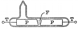
Omitting the intermediate developments of invention, it may be said that Mr. Marconi was the first to recognise that to secure great sensibility in an electric wave detector of this type the following conditions must be fulfilled: An exceedingly small mass of metallic filings must be placed in a very narrow gap between two plugs, the whole being contained in a vessel which is wholly or partly exhausted of its air. Mr. Marconi devoted himself with great success to the development of this instrument, and in a very short time succeeded in transforming it from an uncertain laboratory appliance, capable of yielding results only in very skilled hands, into an instrument certain and simple in its operations as an ordinary telegraphic relay. He did this, partly by reducing its size, and partly by a most judicious selection of materials for its construction. As made at present, the Marconi metallic filings tube consists of a small glass tube, the interior diameter of which is not much more than one-eighth of an inch, which has in it two silver plugs which are bevelled off obliquely. These are placed opposite to each other, so as to form a wedge-shaped gap, about a millimetre in width at the bottom and two, or at most three, millimetres in width at the top (see Fig. 16). The silver plugs exactly fill the aperture of the tube, and are connected to platinum wires sealed through the glass. The tube has a lateral glass tube fused into it, by which the exhaustion is made, which is afterwards sealed off, and this tube projects on the side of the wider portion of the gap between the silver plugs. The sensitive material consists of a mixture of metallic filings, five per cent. silver and ninety-five per cent. nickel, being carefully mixed and sifted to a certain standard fineness. In the manufacture of these tubes, great care is taken to make them as far as possible absolutely identical. Each tube when finished is exhausted, but not to a very high vacuum. The tube so finished is attached to a bone holder, by which it can be held in a horizontal position. The object of bevelling off the plugs in the Marconi tube is to enable the sensitiveness of the tube to be varied by turning it round, so that the small quantity of filings lie in between a wider or narrower part of the gap.[36]
Fig. 16.—Marconi Sensitive Tube or Metallic Filings Kumascope. PP, silver plugs; TT, platinum wires; F, nickel and silver filings.
Other ways of adjusting the quantity of the filings to the width of the gap have been devised. Sometimes one of the plugs is made movable. In other cases, such as the tubes devised by M. Blondel and Sir Oliver Lodge, there is a pocket in the glass receptacle to hold square filings, from which more or less can be shaken into the gap.
An interesting question, which we have not time to discuss in full, is the cause of the initial coherence of the metallic filings in a Branly tube. It does not seem to be a simple welding action due to heat, and it certainly takes place with a difference of potential, which is very far indeed below that which we know is required to produce a spark. On the other hand, it seems to be proved that in a Banly tube, when acted upon by electric waves, chains of metallic particles are produced. The effect is not peculiar to electric waves. It can be accomplished by the application of any high electromotive force. Thus Branly found that coherence may be produced by the application of an electromotive force of twenty or thirty volts, operating through a very high water resistance, and thus precluding the passage of any but an excessively small current. Again, the coherence seems to take place in some cases when metallic particles are immersed in a liquid, or even in a solid, insulator. Processor Branly has, therefore, preferred to speak of masses of metallic granules as radio-conductors, and Professor Bose has divided substances into positive and negative, according as the operation of electromotive force is to increase the coherence of the particles or to decrease it.
It has been asserted that for every particular Branly tube, there is a critical electromotive force, in the neighbourhood of two or three volts which causes the tube to break down and pass instantly from a non-conductive to a conductive condition, and that this critical electromotive force may become a measure of the utility of the tube for telegraphic purposes. Thus, C. Kinsley (Physical Review, Vol. XII., p. 177, 1901) has made measurements of this supposed critical potential for different "coherers," and subsequently tested the same as receivers at a wireless telegraph station of the U.S.A. Signal Corps. The average of twenty-four experiments gave in one case 2·2 volts as the breaking down potential of one of these coherers or Branly tubes, 3·8 volts for a second and 5·5 volts for the third. These same instruments, tested as telegraphic kumascopes, showed that the first of the three was most sensitive.
On the other hand, W. H. Eccles (Electrician, Vol. XLVII., pp. 682 and 715, 1901) has made experiments with Marconi nickel-silver sensitive tubes, using a liquid potentiometer made with copper sulphate, to apply the potential so that infinitesimal spark contacts might be avoided and the changes in potential made without any abruptness. He states that if the coherer tube is continuously tapped, say at the rate of fifty vibrations per second, whilst at the same time an increasing potential is applied to its terminals and the current passing through it measured on a galvanometer, there is no abrupt change in current at any point. He found that when the current and voltage were plotted against each other, a regular curve was obtained, which after a time becomes linear. A decided change occurs in the conductivity of the mass of metallic filings when treated in this manner at voltages lower than the critical voltage obtained by previous methods. He ascertained that there was a complete correspondence between the sensitiveness of the tubes used as telegraphic instruments and the form of the characteristic curve of current and voltage drawn by the above-described method.
In the same manner, K. E. Guthe and A. Trowbridge (Physical Review, Vol. II., p. 22, 1900) investigated the action of a simple ball coherer formed of half a dozen steel, lead or phosphor-bronze balls in slight contact. They measured the current i passing through the series under the action of a difference of potential v between the ends, and found a relation which could be expressed in the form

where V and k are constants.
The current through this ball coherer is, therefore, a logarithmic function of the potential difference between its ends, of the form

and exhibits no discontinuity.
The inference was drawn that the "resistance" is due to films of water adhering to the metallic particles through which electrolytic action occurs.
A good metallic filings tube for use as a receiver in Hertzian wave telegraphy should exhibit a constancy of action and should cohere and decohere, to use the common terms, sharply, at the smallest possible tap. It should not have a current passed through it by the external cell of more than a fraction of a milliampere, or else it becomes wounded and unsensitive.
The investigations which have already taken place seem to show pretty clearly that the agency causing the masses of filings to pass from a non-conductive to a conductive condition is electromotive force, and that, therefore, it is the electromotive force set up in the aerial by the incident waves which is the effective agent in causing the change in the metallic filings tube, when this is used as a telegraphic kumascope. This transformation of the tube from a non-conductor to a conductor is made to act as a circuit-closer, completing the circuit, by means of which a single cell of a local battery is made to send current through an ordinary telegraph relay, and so by the aid of a second battery operate a telegraphic printer or recorder of any kind. Hence it is clear that after one impact, the metallic filings tube has to be brought back to its non-conductive condition, and this may be achieved in several ways. (1) By the administration of carefully-regulated taps or shocks or by rotating the tube on its axis; (2) by the aid of an alternating current; (3) in those cases where filings of magnetic metals are employed, by magnetism.
The decoherence by taps was discovered by Branly,[37] and Popoff, following the example of Sir Oliver Lodge, employed an electric bell arrangement for this purpose.[38]
Mr. Marconi, in his original receiving instruments, placed an electromagnet under the coherer tube with a vibrating armature like an electric bell.[39] This armature carries a small hammer or tapper, which, when set in action, hits the tube on the under side, and various adjusting screws are arranged for regulating exactly the force and amplitude of the blows. This tapper is actuated by the same current as the Morse printer, or other telegraphic recorder, so that when the signal is received and the metallic filings tube passes into the conductive condition and closes the relay circuit, this latter in turn closes the circuit of the Morse printer or other recorder, and at the same time, a current passes through the electromagnet of the tapper and the tube is tapped back. This sequence of operations requires a certain time which limits the speed of receiving. The tapper has to be so arranged that it is possible to receive and to record not only the dot but a dash on the Morse system. The dash is really a series of closely adjacent dots, which run together in virtue of the inertia and inductance of the different parts of the whole receiving apparatus. The adjustment has so to be made that, whilst the dash is being recorded and a continuous tapping is kept up, yet, nevertheless the continued electromotive force in the aerial, due to the continually arriving trains of waves, is able to act against the tapping and to keep the filings in the tube in the conductive condition. Hence, the successful operation of the arrangement requires attention to a number of adjustments, but these are not more difficult, or even as difficult, as those involved in the use of many telegraphic receivers employed in ordinary telegraphy with wires.
Mr. Marconi also introduced devices for preventing the sparks at the contacts of the electromagnetic hammer from directly affecting the tube, and also to prevent the electric oscillations which are set up in the aerial from being partly shunted through other circuits than that of the sensitive tube. We pass on to notice the remaining devices for restoring the metallic filings tube to a condition of sensitiveness or receptiveness.
A method for doing this by alternating currents is due to Mr. S. G. Brown.[40] The pole pieces of the coherer tube are made of iron, and they are enveloped in magnetising coils traversed by an alternating electric current. Between these pole pieces is placed a small quantity of nickel or iron filings, and under the action of the electromotive force, due to an electric wave acting on them, may be made to cohere in the usual fashion; but the moment that the wave ceases, the alternating magnetism of the electrodes causes the filings to drop apart or decohere. In place of the alternating current, Mr. Brown finds that a revolving permanent magnet can be used to produce the alternating magnetisation of the pole pieces of the sensitive tube or coherer.
The third method of causing the decoherence of the filings is that due to T. Tommasina. He found that when a Branly tube is made with filings of a magnetic metal, such as iron, nickel and cobalt, the decoherence of the filings can be produced by means of an electromagnet placed in a suitable position under the tube.[41] The explanation of this fact seems to be that, when an electric wave falls upon the tube or when any other source of electromotive force acts upon it, chains of metallic particles are formed, stretching from one electrode to the other. Tommasina contends that he has proved the existence of these chains of particles by experiments made with iron filings; and R. Malagoli,[42] in referring to Tommasina's assertion, states that it can be witnessed in the case of brass filings placed between two plates of metal and immersed in vaseline oil, when a difference of potential is made between the plates.
T. Sundorph[43] says he has confirmed Tommasina's discovery of the formation of these chains of metallic particles in the coherer. The filings do not all cling together, but certain chains are formed which afford a conducting path for the current subsequently passed through the coherer from an external source. Accordingly, Tommasina's method of causing decoherence in the case of filings of magnetic metals is to pull them apart by an external magnetic field; and he stated that decoherence can be effected more easily and regularly in this way than by tapping. Whilst on this point, it may be mentioned that C. Tissot[44] says that he has found that the sensitiveness of a coherer formed of nickel and iron filings can be increased by placing it in the magnetic field, the lines of which are parallel to the axis of the tube. According to MM. A. Blondel and G. Dobkevitch, this is merely the result of an increased coherence of the particles.
Quite recently, Sir Oliver Lodge and Dr. Muirhead have employed as a self-restoring coherer or kumascope a steel disc revolved by clockwork, the edge of which just touches a globule of mercury covered with a thin film of paraffin oil. The contact is made between the mercury and the steel by the electric wave generating an electromotive force in the aerial, sufficient to break through the thin film of oil. When the wave stops, the circuit is again interrupted automatically.
This device is used without a relay to actuate directly a syphon recorder as used in submarine telegraphy. The working battery employed with it must only have an electromotive force of about a tenth of a volt. It may be used also with a telephone in circuit and can, therefore, be employed either for telegraphic or telephonic reception.[45]
Fig. 17.—Italian Navy Self-restoring Kumascope. C, carbon plug; I, iron plug; M, mercury globule; A, aerial; B, battery; T, telephone; S, adjusting screw.
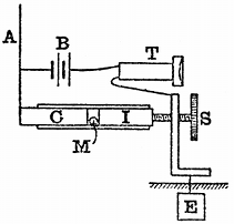
One of the most sensitive of these self-restoring kumascopes is the carbon-steel-mercury coherer, the invention of which has been attributed to Castelli, a signalman in the Italian Navy,[46] but also stated on good authority to have been the invention of officers in the Royal Italian Navy, and has, therefore, been called the Italian Navy coherer.[47] This instrument has been arranged in several forms, but in the simplest of these it consists of a glass tube, having in it a plug of iron and a plug of arc-lamp carbon, or two plugs of iron with a plug of carbon between them. The plugs of iron, or of iron and carbon, are separated by an exceedingly small globule of mercury, the size of which should be between one and a-half and three millimetres. The plugs closing the tube must be capable of movement, one of them by means of a screw, as shown in the diagram (Fig. 17), taken from a patent specification communicated to Mr. Marconi by the Marchese Luigi Solari, of the Royal Italian Navy. One of the plugs of this tube is connected to the aerial and the other to the earth, and they are also connected through another circuit composed of a single dry cell and a telephone. The arrangement then forms an extremely sensitive detector of electric waves or of small electromotive forces, or, if a wave falls on the aerial, the electromotive force at once improves the contact between the mercury and the plugs, and therefore causes a sudden increase in the current through the telephone, giving rise to a sound; but when the wave ceases, or the electromotive force is withdrawn, the resistance falls back again to its origin value, and the arrangement is, therefore, self-acting, requiring no tapping or other device for restoring it to receptivity.
A very ingenious form of combined telephone and coherer has been devised by T. Tommasina.[48] In this instrument the diaphragm of an ordinary Bell telephone carries upon it a very small carbon or metallic coherer. This coherer is connected in between the aerial and the earth, and is also in circuit with a battery and the electromagnet of a telegraphic relay. When this relay operates it closes the circuit of another battery which is placed in series with the telephone coil. The moment the current passes through the telephone coil it attracts, and therefore vibrates, the diaphragm and shakes up the metallic filings. If an observer, therefore, places the telephone to his ear, he hears a sound corresponding to every train of waves incident upon the aerial. With this arrangement, one can obtain two different kinds of results, according to the nature of the cohering powder placed in the cavity in the diaphragm. First, if the powder consists of a non-magnetic metal, gold, silver, platinum or the like, the receiver will be very sensitive; and at the same time the current passing through it when it is cohered will be sufficient to work a sensive recording apparatus in series with the telephone coil. Secondly, if the metallic powder placed in the cavity is a magnetic metal, the receiver will be somewhat less sensitive, but will work with more precision, because of the magnetic action of the magnet of the telephone upon the cohering powder. If no recording apparatus is used, the observer must write down the signals as heard in the telephone, since corresponding to a short spark at the transmitting station, a single tick or short sound is heard at the telephone, and corresponding to a series of rapidly successive sparks, a more prolonged sound is heard in the telephone. These two sounds, as already explained, constitute the dot and the dash of the Morse signals.
We may, in the next place, refer to that form of kumascope in which the action of the wave or of electromotive force is not to decrease the resistance of a contact, but to increase that of an imperfect contact. As already mentioned, Professor Branly discovered long ago that peroxide of lead acts in an opposite manner to metallic filings, in that when placed in a Branly tube it increases its resistance under the action of an electric spark, instead of decreasing it. Again, Professor Bose has found that fragments of metallic potassium in kerosene oil behave in a similar manner, and that certain varieties of silver, antimony and of arsenic, and a few other metals, have a similar property. Branly tubes, therefore, made with these materials, or any arrangements which act in a similar manner, have been called "anti-coherers." The most interesting arragement which has been called by this name is that of Schäfer.[49] Schäfer's kumascope is made in the following manner: A very thin film of silver is deposited upon glass, and a strip of this silver is scratched across with a diamond, making a fine transverse cut or gap. If the resistance of this divided strip of silver is measured, it will be found not to be infinite, but may have a resistance as low as forty or fifty ohms if the strip is thirty millimetres wide. On examining the cut in the strip with a microscope, it will be found that the edges are ragged and that there are little particles of silver lying about in the gap. If, then, an electromotive force of three volts or more is put on the two separated parts of the strip, these little particles of silver fly to and fro like the pith balls in a familiar electrical experiment, and they convey electricity across from side to side. Hence a current passes having a magnitude of a few milliamperes. If, however, the strip is employed as a kumascope and connected at one end to the earth and at the other end to an aerial, when electric waves fall upon the aerial, the electrical oscillations thereby excited seem to have the property of stopping this dance of silver particles and the resistance of the gap is increased several times, but falls again when the wave ceases. If, therefore, a telephone and battery are connected between two portions of the strip, the variation of this battery current will affect the telephone in accordance with the waves which fall upon the aerial, and the arrangement becomes therefore a wave-detecting device. It is said to have been used in wireless telegraph experiments in Germany up to a distance of ninety-five kilometres.
We must next direct attention to those wave-detecting devices which depend upon magnetisation of iron, and here we are able to record recent and most interesting developments. More than seventy years ago Joseph Henry, in the United States, noticed the effect of an electric spark at a distance upon magnetised needles.[50] Of recent times, the subject came back into notice through the researches of Professor E. Rutherford,[51] who carried out at Cambridge, England, in 1896, a valuable series of experiments on this subject. He found that if a magnetised steel needle or a very small bundle of extremely thin iron wires is magnetised and placed in the interior of a small coil, the ends of which are connected to two long collecting wires, then an electric wave started from a Hertz oscillator at a distance causes an immediate demagnetisation of the iron. This demagnetisation he detected by means of the movement of the needle of a magnetometer placed near one end of the iron wire. Although Rutherford's wave detector has been much used in scientific research, it was not, in the form in which he used it, a telegraphic instrument, and could not record alphabetic signals.
Fig. 18.—Marconi Magnetic Receiver. W1W2, wheels; I, iron wire band; P, primary coil; S, secondary coil; T, telephone; A, aerial; E, earthplate.
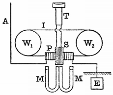
Not long ago Mr. Marconi invented, however, a telegraphic instrument based upon his discovery that the magnetic hysteresis of iron can be annulled by electric oscillations. In one form, Mr. Marconi's magnetic receiver is constructed as follows[52] (see Fig. 18): An endless band of thin iron wire composed of several iron wires about No. 36 gauge, arranged in parallel, is made to move slowly round on two pulleys, like the driving belt of a machine. In one part of its path the wire passes through a glass tube, on which are found two coils of wire, one a rather short, thick coil, and the other a very fine, long one. The fine, long coil is connected with a telephone, and the shorter coil is connected at one end to the earth and the other to the aerial. Two permanent horse-shoe magnets are placed as shown n Fig. 18, with their similar poles together, and, as the iron band passes through their field, a certain length of it is magnetised, and owing to the hysteresis of the material, it retains this magnetism for a short time after it has passed out of the centre of the field. If then an electric oscillation, coming down from the aerial, is passed through the shorter coil, it changes the position of the magnetised portion of the iron and, so to speak, brings the magnetised portion of iron back into the position it would have occupied if the iron had had no hysteresis. This action, by varying the magnetic flux through the secondary coil, creates in it an electromotive force which causes a sound to be heard in the telephone connected to it. If at a distant place a single wave or train of waves is started and received by the aerial, this will express itself by making an audible tick in the telephone, and if several groups of closely adjacent wave trains are sent, these will indicate themselves by producing a rapid series of ticks in the telephone, heard as a short continuous noise and taken as equivalent to the Morse dash.
It was by means of this remarkably ingenious instrument that Mr. Marconi was able, in the summer of 1902, to detect the waves sent out from Poldhu on the coast of Cornwall, and receive messages as far as Cronstadt in the Baltic, in one direction, and as far as Spezzia in the Mediterranean in another direction, and also to receive messages across the Atlantic from the power stations situated in Glace Bay, Nova Scotia, and from one at Cape Cod in Massachusetts, U.S.A., in December, 1902.
There can be no question that this magnetic detector of Mr. Marconi's, used in connection with a good telephone and an acute human ear, is the most sensitive device yet invented for the detection of electric waves and their utilisation in telegraphy without continuous wires. It is marvellously simple, ingenious and yet effective, as a Hertzian wave telegraphic receiver.
Whilst on the subject of magnetic wave detectors, the author may describe experiments that he has been recently making to construct a Hertzian wave detector on the Rutherford principle, which shall be strictly quantitative. All the receivers of the coherer type and electrolytic type give no indications that are at all proportional to the energy of the incident wave. Their indications are more or less accidental and depend upon the manner in which the receiver was last left. There is a great need for a quantitative wave detector, the indications of which shall give us a measure of the energy of the arriving wave. It is only by the possession of such an instrument that we can hope to study properly the sending powers of various transmitters or the efficiency of different forms of aerial or devices by which the wave is produced. This magnetic receiver is constructed as follows: