Chapter V · THE 3-INCH FIELD GUN.
Reading edition
THE GUN.
The Gun is known officially as the 3-inch Field Gun, Model 1905. It is a built-up construction of nickel-steel and consists of a tube with a rifled bore, 3 inches in diameter, upon which are shrunk the jacket, locking hoop and front clip hoop. The jacket reinforces the rear half of the tube. The locking hoop serves to secure the jacket from any longitudinal movement to the rear. On the under side of the gun, extending the entire length of the jacket, locking hoop, and front clip, are formed two recoil guides or clips which fit over and secure the gun to the guide rails of the cradle. When the gun is fired, it slides along the guide rails. The dust guard covers the part of the guide rails between the locking hoop and the front clip. The rifling of the bore is right-hand twist and starts with 0 turns at the breech increasing to 1 turn in 25 calibers at 10 inches from the muzzle, then uniform to the muzzle.
Weights and Dimensions.
Weight of gun 788 lbs.
Calibre 3 inches
Length about 7 feet
Number of lands and grooves 24
Muzzle velocity 1700 ft. sec.
Maximum pressure per sq. in. 33,000 lbs.
Limit of depression (90 mils.) 5 degrees
Maximum elevation (265 mils.) 15 degrees
Maximum range, trail sunk, about 8,500 yds. (5 M)
Range at 15° elevation (265 mils) 6,000 yds. (3½ M)
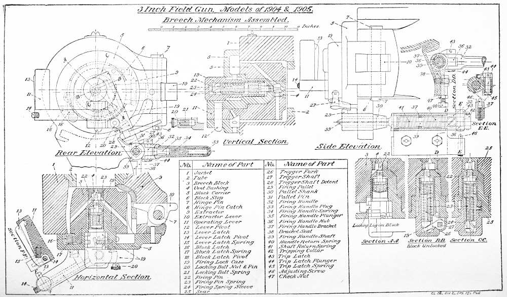
3 Inch Field Gun, Models of 1904 & 1905.
Breech Mechanism Assembled.
Nomenclature of parts of Gun:—
Jacket.
Locking hoop.
Tube.
Bore.
Rifling.
Lands.
Grooves
Breech recess.
Front clip.
Muzzle.
Dust guard.
Recoil guides or clips.
Chamber.
Recoil lug.
Line sight (front and rear).
Handy oilers.
THE BREECH MECHANISM.
The breechblock is of the interrupted-screw type, and is provided with four threaded and four slotted sectors. The front end of the axial recess in the block is closed by a bushing. Four ventholes lead from a cavity in the bushing and permit the escape of gas to the rear in case of a ruptured primer. On the rear face of the breechblock are cut gear teeth, in which the gear teeth of the operating lever bevelgear mesh. The breechblock is concentrically mounted on a hub on the block carrier, in which the firing-lock case is fitted. Its position in the breech of the gun with reference to the axis of the bore is eccentric.
The breechblock is closed or locked by a continuous movement of the operating lever. When the block is swung to the closed position the front face of the block latch comes in contact with the rear face of the breech of the gun, thus forcing the latch out of the notch in the breechblock and back into a recess in the carrier. By continuing the motion of closing the mechanism, the breechblock is then rotated on the hub of the carrier and its threads engage with corresponding ones in the gun. When the breechblock is in the closed position, a lug on the firing-lock case serves to lock the carrier to the breechblock and prevents displacement due to a blowback.
The firing mechanism belongs to that type known as a continuous-pull mechanism; that is, no cocking of the firing-pin is required.
The firing-lock case is eccentrically fitted in the hub of the block carrier, in such a position that the axis of the firing-pin is always in line with the bore of the gun. The vent bushing in the front end of the breech block through which the firing pin passes when in the fired position, is fitted eccentrically with reference to the breechblock. This eccentric arrangement of the breechblock, masks the point of the firing-pin and prevents any possible contact between the pin and the primer in the cartridge case when the block is unlocked. The block will be practically fully locked before any contact between the firing-pin and primer can take place.
Nomenclature of important parts of Breech & Firing Mechanism.
Mod. 1905:—
Name of Part Where located
Breech Block On block carrier
Vent Bushing Front end of block
Block Carrier Hinged to jacket; supports block
Block Stop Screwed into front face of carrier
Hinge Pin Hinges carrier to jacket
Hinge Pin Catch In hinge pin
Extractor In breech recess
Extractor Lever Mounted on hinge pin
Operating Lever Pivoted on block carrier
Lever Pivot Pivots lever on block carrier
Lever Latch In operating lever
Lever Latch Spring In operating lever, lower part
Lever Latch Pivot In operating lever, lower part
Block Latch In recess in carrier
Block Latch Spring Around latch bolt
Firing Lock Case In hub of the block carrier
Locking Bolt Nut and Pin On firing lock case, rear face of carrier
Firing Pin In axle hole, center of firing lock case
Firing Pin Spring Around firing pin
Firing Spring Sleeve Around firing pin spring
Sear In slot in firing lock case
Trigger Fork Rear end firing lock case
Trigger Shaft On rear end firing lock case
Trigger Shaft Detent On trigger shaft
Firing Pallet On pallet shank
Pallet Shank On recoil lug of gun
Firing Handle On firing handle shaft
Firing Handle Bracket Attached to right side of cradle
Firing Handle Shaft Assembled in bracket, right side of cradle
Trip Latch Attached to trip latch plunger
Trip Latch Plunger Assembled to firing handle
Adjusting Screw Assembled to firing handle bracket
Check Nut Assembled in adjusting screw
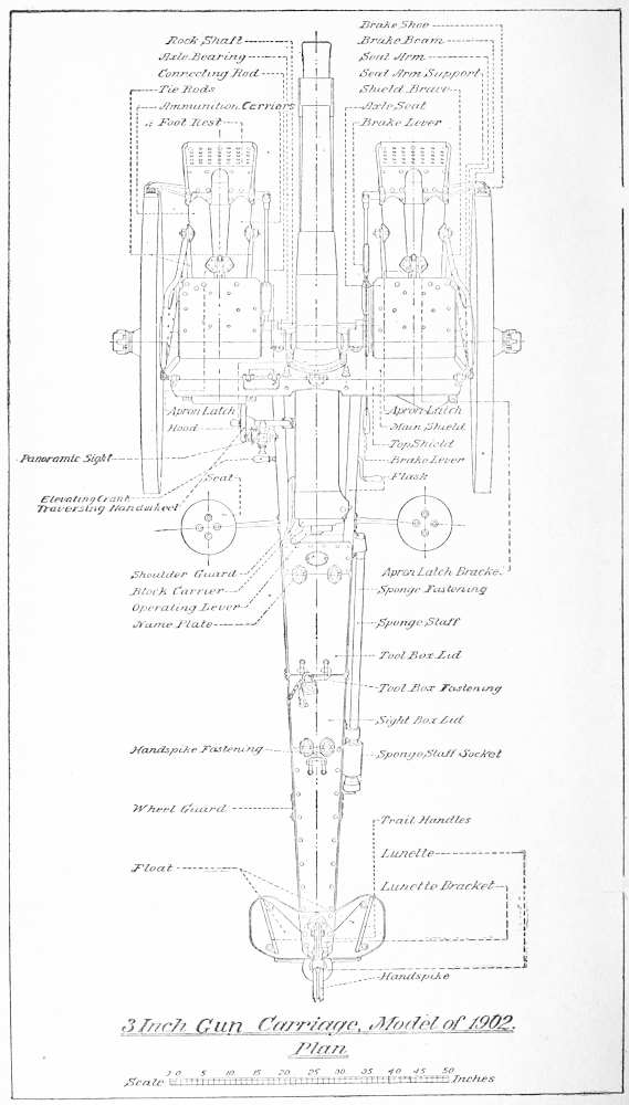
3 Inch Gun Carriage, Model of 1902. Plan
THE GUN CARRIAGE.
The gun carriage for the 3-inch gun Model 1905 is of the type known as the long-recoil, in which the gun is permitted a sufficient length of recoil (about 45 inches) upon the carriage to render the latter stationary under firing stresses. The gun is mounted upon a cradle which forms a housing for the recoil controlling parts. The cradle rests upon the rocker and has a small traversing motion of 70 mils on each side of the axis of the carriage. The rocker is journaled upon the axle and its rear end is supported by the elevating mechanism, which is seated in the trail.
The principal parts of the carriage are the wheels, axle, trail and elevating mechanism forming the lower carriage, the cradle and recoil-controlling parts constituting the upper carriage, and the rocker and traversing mechanism intermediate between the two. In addition there are provided shields, ammunition carriers, the road brake, and the axle seats.
The Wheels and the Axle. The wheels are a modified form of the Archibald pattern, 56 inches in diameter, with 3-inch tires. The axle is hollow and forged from a single piece of steel. The wheels are held on by the wheel fastenings.
Trail.—The trail consists of two steel flasks of channel section with the flanges turned inward, tied together by transoms and plates to form the sight and the tool boxes. Attached to the trail are the trail spade, float trail handspike, trail handles and the lunette.
Elevating Gear.—The elevating gear is of double-screw type and consists of an inner and outer elevating screw, an elevating-gear bracket, an elevating bevel gear, two elevating bevel pinions, and two elevating crank shafts. The inner elevating screw is a steel screw, threaded with a right-hand thread. It is attached at its upper end by the elevating pin to the rear end of the rocker. The outer elevating screw is of bronze and is threaded on the exterior with a right-hand thread to take the inner elevating screw. On the exterior are also cut two longitudinal keyways, in which the keys of the bevel gear work.
Traversing Mechanism.—The traversing mechanism consists of a shaft, called the traversing shaft, mounted in bearings in the traversing-gear case, and a traversing nut moving longitudinally on the shaft, but restrained from turning with it by its bearings in the gear case. A cylindrical lug on top of the nut fits in a hole in a bronze traversing link, the right end of which is pivoted by the traversing-link pivot to the traversing lug on the underside of the cradle. This pivot is secured to the cradle-traversing lug by a nut and split pin. The left bearing of the traversing shaft is split for the purpose of assembling and rests between two collars on the shaft. The bearing, with the shaft in place, is slipped into its seat in the gear case, where it is held in position by two pins.
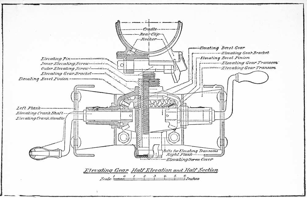
TRAVERSING GEAR, VERTICAL SECTION
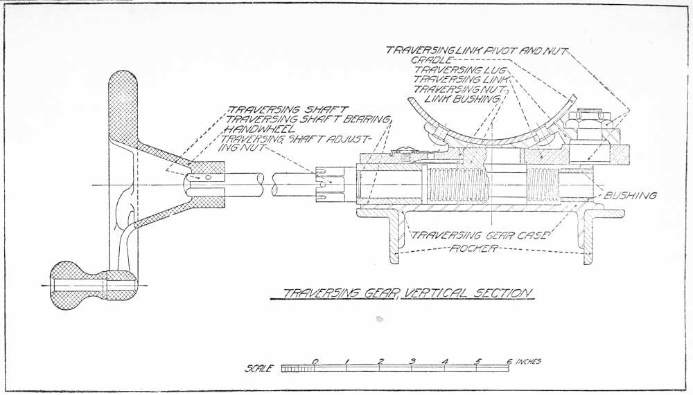
Elevating Gear Half Elevation and Half Section
The Cradle Complete.—The cradle supports the gun, guides it in recoil, and forms a housing for the recoil-controlling parts; it consists of a flange steel body with the upper edges flanged outward. The flanges are bronze lined, engage the clips on the gun, forming the guide rails for the gun on recoil. Riveted to the bottom of the cradle are four steel forgings, the pintle, traversing lug, rear clip, and elevating and traversing lock lug. The pintle fits the pintle socket in the rocker and forms a bearing upon which the cradle is traversed. The traversing lug has been heretofore mentioned as affording a point of attachment for the traversing-link pivot. The cradle rear clip, in addition to embracing the rear end of the rocker, has a broad bearing on the latter directly over the point of attachment of the elevating screw.
To relieve the pointing mechanism from all strains in travelling, an elevating and traversing lock is provided, by which the cradle may be securely locked to the trail.
The recoil-controlling parts contained inside the cradle are the cylinder, the piston rod, the counter-recoil buffer, the counter-recoil springs and the spring support.
To the rear end of the cradle is riveted a steel cradle head, rear, through which the cylinder moves in recoil and projects for attachment to the recoil lug on the gun by means of the cylinder end stud and nut. The front end of the cradle is closed by the cradle head, front, and the retaining ring.
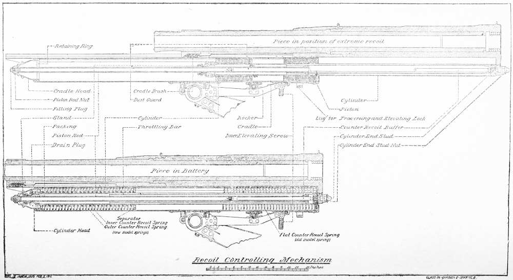
Recoil Controlling Mechanism
The cylinder lies inside the cradle and is surrounded by the counter-recoil springs. Its rear end is closed and has a projection on the inside to which is screwed the counter-recoil buffer, a tapered bronze rod which fits with small clearance into a bore at the rear end of the piston-rod. The front end of the cylinder is closed by a bronze oiltight gland, through which the piston-rod slides. The cylinder is filled with a neutral oil called hydroline. The interior of the cylinder is cylindrical. Three longitudinal ribs or throttling bars of uniform width but varying height extend along the interior from the rear end to within 19 inches from the front end. Three notches are cut in the piston head, forming ports for the passage of the liquid from one side of the piston to the other. The height of the throttling bars is calculated so that the resistance which the liquid offers, plus the resistance of the springs, is constant and such that the recoil will be checked at the desired point. During recoil the front end of the cylinder is supported by the spring support.
The piston rod is of steel, and is provided with a bronze piston head, screwed against a shoulder at the rear end. The head has three notches cut in its perimeter, which fit over the throttling-bar projections on the cylinder wall. The rear end of the piston is bored out to take the counter-recoil buffer. In counter recoil the oil in this bore can escape only by a small clearance. In this way the return of the gun into battery is so eased and regulated that very little shock and consequent derangement of the aim of the piece occur. The front end of the piston-rod is attached to the cradle head, front, by means of the piston-rod nut.
The counter-recoil springs (three in number each 36 inches long) are helical, being made from a rectangular steel bar coiled on edge. They are assembled in the cradle, end to end around the cylinder and bear in front against the spring support and in the rear against the cradle head, rear. They are assembled under an initial compression of approximately 750 lbs. which is sufficient to return the gun into battery at the maximum elevation. In place of the single counter-recoil springs a set of three inner and three outer counter-recoil springs is also being issued.
The spring support forms a support for the front end of the cylinder and a bearing for the front end of the spring column. It has guide lugs which fit into and glide along guide rails inside the cradle during recoil. The spring support is held in place by the retaining ring.
Action of the Mechanism.
The action of the recoil mechanism when the gun is fired is as follows:—The gun moves to the rear 45 inches on the cradle, carrying with it the cylinder and compressing the recoil springs. The piston rod being attached to a fixed part of the carriage in front, (the cradle-head) does not move. Therefore, since the cylinder moves to the rear, the oil in it must pass from one side of the piston head to the other. The energy of recoil of the gun is therefore absorbed by the resistance which the oil offers when being forced through small openings between the notches in the piston head and the throttling bars along the inside of the cylinder and also by the resistance of the counter-recoil springs to additional compression. The energy stored up by the springs during this compression, returns the gun and cylinder to the firing or original position. This return movement is eased and regulated by the counter-recoil buffer. The piston rod pull and the spring resistance are transmitted to the carriage, but owing to the latter’s weight and the resistance opposed to the trail spade by its engagement in the ground the carriage remains stationary.
Weights and Dimensions.
Weight of gun and carriage complete 2,520 lbs.
Width of track 60 inches
Length of recoil on carriage 45 inches
Amount of traverse of gun on carriage 140 mils
Nomenclature of important parts of the Gun Carriage:—
Axle
Trail, consisting of—
Flasks (right and left)
Tool box
Elevating gear transom
Rear sight box
Spade
Spade Edge
Float
Handspike fulcrum
Cradle, head, rear
Gun slides or Guide Rails
Cradle Pintle
Traversing lug
Rear clip
Lug for elevating and traversing lock
Bracket seat, firing handle
Quadrant fastening
Rear-sight bracket support
Front-sight bracket support
Spring-support guides
Retaining ring, with hasp and fastening
Cradle head, front
Shoulder guard
Cradle brush
Recoil-indicator throw
Recoil indicator
Cylinder head
Cylinder with cylinder end screwed in
Cylinder end stud and nut
Counter-recoil buffer
Rings, packing
Gland
Piston rod, with plug, screwed in
Piston
Piston-rod nut
Filling plug with gasket
Drain plug
Spring support
Counter-recoil springs
Rocker
Cradle Pintle socket
Elevating and traversing lock
Traversing mechanism, consisting of—
Traversing-gear case
Traversing plate
Handwheel with handle and spindle
Traversing shaft
Traversing-shaft bearing in two parts
Traversing link with bushing
Traversing-link pivot with nut
Azimuth pointer and scale
Elevating mechanism, consisting of—
Elevating pin
Inner elevating screw
Outer elevating screw
Wheels guards
Trail handles
Trail seats
Trail-seat supports
Sponge-staff socket
Name plate
Handspike
Lunette
Cradle, consisting of—
Cradle body
Elevating bevel gear
Elevating bevel pinions
Elevating crank shafts, with handles
Elevating screw cover
Axle seats, include—
Seat arms
Seat-arm guards
Foot rests
Tie rods
Shield braces
Apron shield
Apron latches
Main shield, consisting of—
Main shield
Hood
Shutter, open-sight port
Shutter, panoramic-sight port
Top shield, consisting of—
Top shield
Top shield fastenings
Road brake, includes—
Brake beams
Brake shoes
Springs with covers
Brake rods
Brake lever
Brake shaft
Brake segment with two segment racks
Ammunition carriers
Range quadrant case
Panoramic sight case
Front sight
Rear sight, consisting of—
Rear-sight bracket with shank socket
Rear-sight shank
Panoramic sight
Range quadrant
Wheels, consisting of—
Felloe, segments
Spokes
Tires
Hub boxes
Hub liners
Hub-latch plungers
Oil Valve
Carriage bolts and nuts
Hub bands
Hub caps
Wheel fastenings
Plugs
THE 3-INCH GUN (CAISSON) LIMBER.
The limber is of metal throughout excepting the spokes and felloes of the wheels. The principal parts are the wheels, axle, pintle, frame, ammunition chest, pole, doubletree, singletrees, and neck yoke.
The wheels and wheel fastenings are the same as, and interchangeable with those used on the carriage. Seats for three cannoneers are provided by a perforated metal bucket-holder on top of the chest. The paulin issued to each limber serves as a seat cushion and is held in place by paulin straps. Grip straps are also provided for use by the cannoneers when the carriage is moving at rapid gaits. On the sides and front of, and under the ammunition chest, suitable straps, brackets and connections are provided for securing all tools and accessories. With each limber are issued three tubular oil cans, each in the form of a cartridge and with a capacity of two-thirds of a gallon. These are intended to hold hydroline, lubricating and coal oil and are carried in the central row of cartridge holes in the ammunition chest.
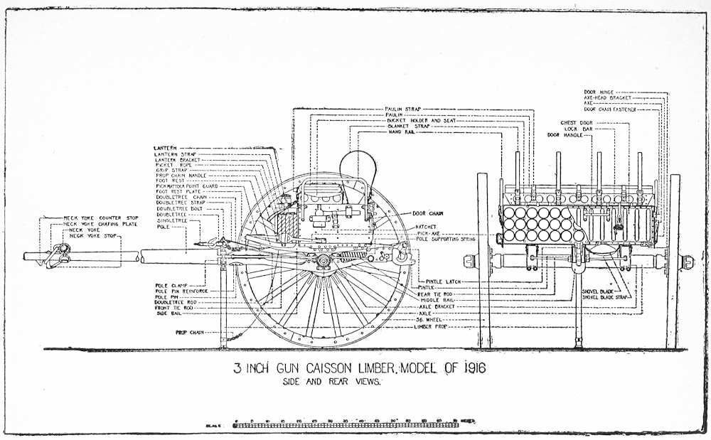
3 INCH GUN CAISSON LIMBER, MODEL OF 1916 SIDE AND REAR VIEWS.
Weights and Dimensions.
Weight of limber, completely equipped and loaded 1740 lbs.
Weight of gun, carriage and limber, completely equipped and loaded 4260 lbs.
Number of rounds carried 36
Nomenclature of important parts of limber:—
Pole, complete, consisting of—
Pole body
Neck-yoke counter stop
Neck-yoke stop
Neck-yoke chafing plate
Butt reinforce
Doubletree
Doubletree rods
Name plate
Limber prop
Foot rest
Tie-rods
Pintle with bearing, consisting of—
Pintle
Pintle latch
Pintle latch spring
Wheels and wheel fastenings
Axle
Middle rail
Side rails
Ammunition chest, consisting of—
Hand rail
Door chains
Shot bolts
Bucket holder
Chest rails
Chest-rail connections
Body
Door
Cartridge holes
Diaphragms
Lantern brackets
Grip-straps
Paulin straps
Various tool brackets
Various tools
Paulins
Picket ropes
Lanterns
Canvas buckets
THE CAISSON
The Caisson is made of metal throughout with the exception of the spokes and felloes of the wheels. The principal parts are the wheels, axle, pintle, lunette, apron shield, fuze setter bracket, frame, road brake, and ammunition chest.
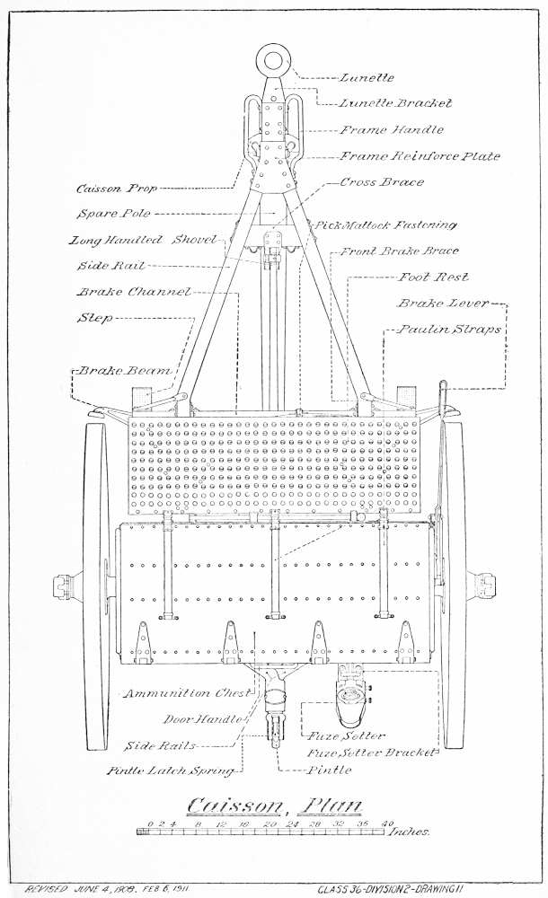
Caisson, Plan
The wheels and wheel fastenings are interchangeable with those of the gun carriage and the limber. The caisson road brake is modeled after that of the gun carriage, all parts as far as possible being interchangeable. The frame upon which the ammunition chest rests, is diamond shaped, and consists principally of two steel side rails riveted to lugs on the axle, meeting in front to form the lunette for attachment to the limber, and in rear to form a pintle for attachment of another caisson in case it is desired to tow several caissons by one team and limber, as for instance in the ammunition train. In other respects the construction is similar to that of the limber excepting that the ammunition chest is much larger and has a capacity of 70 rounds. The front of the chest and the chest door are made of armor plate. A bracket for the fuse setter is also provided. An apron shield, similar to the one on the gun carriage is hinged under the axle, giving the cannoneers at the caisson full protection. A spare-pole body can be carried under the caisson frame, large end of pole to the front. On the sides and front of, and under the ammunition chest, suitable straps, brackets and connections are provided for securing all tools and accessories. To lock the caissons and limbers, a padlock is provided. These locks are interchangeable and can be unlocked by the same key. This key is marked “Ammunition.”
Weights and Dimensions.
Weight of caisson only, completely equipped and loaded 2820 lbs.
Weight of caisson and limber, both completely equipped and loaded with 106 rounds 4560 lbs.
Number of rounds of ammunition carried in caisson only 70
Nomenclature of important parts of Caisson:—
Wheels
Wheel fastenings, complete
Axle
Middle-rails
Side rails
Pintle with bearing, consisting of—
Pintle
Pintle latch
Pintle-latch spring
Name plate
Channel supports
Frame handles
Lunette, with nut
Caisson prop, with chains
Road brake, consisting of—
Brake-beams
Brake shoes
Brake rods
Brake-rod springs and covers
Brake shaft, with two keys
Brake segment
Segment rack
Brake lever
Spare-pole fastening
Ammunition chest, consisting of—
Diaphragms
Grip-straps
Paulin-straps
Chest rails
Foot rest
Handrails
Door props
Door handles
Hand rails
Supports and Brackets for attaching various tools and accessories
Apron
Apron latches
Fuze-setter bracket
Fuze-setter latch
Fuze setter
Paulin
Picket ropes
Various tools and accessories
Spare pole
To Dismount and to Assemble Parts of the Gun and Carriage.
To dismantle and to assemble the breech mechanism.—Grasp the operating lever and open the breech; when the block is open, force the block latch out of its seat in the block by gently pressing it into its seat in the carrier. Take hold of the block and revolve it to the left until it stops; then pull it to the rear, taking care not to drop it. The block latch can now be readily removed. After the firing-lock case has been removed the operating lever can be removed by forcing its pivot up from beneath by a gentle pressure from the palm of the hand. The lever latch can be removed by pressing in on the latch at a point near its lower end opposite its pivot; a hole in the latch is cut eccentric with reference to the pivot and a shoulder on the pivot prevents their displacement until the latch is forced in and the hole is concentric with the pivot. When this occurs, the pivot can be readily pulled out and the latch removed. To remove the block carrier force the hinge pin up by hand until it can be caught by the head, and by swinging the carrier back and forth, if the pin sticks, it can readily be removed, taking care not to drop the extractor lever. The extractor can now be removed from the gun.
To dismantle and to assemble the firing-lock case and mechanism.—Take hold of the milled headed locking bolt situated at the lower end of the firing-lock case, pull it to the rear; at the same time revolve the firing-lock case upward about 45° and pull it gently to the rear. This will remove the case with the firing mechanism complete from the gun. Press the trigger-shaft detent until it disengages from the notch in the firing-lock case. This will allow the trigger shaft with its detent, to be withdrawn. Then gently press on the front end of the firing pin, forcing it back into the casing. This will allow the trigger fork to fall out. Then, with one finger placed on the front end of the sear, force it outward; at the same time grasp the front end of the firing pin, which is roughened for the purpose. Give it a sharp pull. This will remove the firing-pin spring and sleeve from the casing. Then place the front end of the firing pin against a block of wood, bear down on the firing-spring sleeve until the spring is compressed sufficiently to disengage the slot in the rear end of the sleeve from the small lug on the rear end of the firing pin; slightly turn the sleeve, and then the sleeve can be separated from the spring and pin. By an unscrewing motion the spring can be removed from the pin. The sear can be removed by gently pressing it in toward the center of the casing.
To assemble, reverse these operations, taking care before driving too hard on the end of the trigger shaft that the square hole in the trigger fork is in position to receive the tapered end of the trigger shaft. No tools are required for assembling or dismantling this mechanism.
To remove the recoil indicator.—The ends of the clips of the recoil-indicator guide are bent down to form stops to hold the indicator in place. To remove the indicator, these parts are opened up sufficiently to permit sliding the indicator out of the guide. When the indicator is assembled, these clips should always be closed down to prevent its loss.
To dismount the gun.—Elevate the muzzle slightly. Remove the recoil indicator throw, unscrew the cylinder-end stud nut, and shove the gun to the rear until the clips are free from the guides. As the gun slides off the cradle, it must be properly supported. For this purpose, from 6 to 8 men working in pairs with lifting bars are required.
To mount the gun.—Depress the muzzle slightly. Shove the piece from the rear over the cradle guides with the clips engaging the guides. Assemble the cylinder-end stud nut, taking care that the locking stud on the recoil lug enters one of the recesses provided for it in the end of the cylinder. Assemble the recoil indicator throw. The dust guard should be assembled with the gun.
In moving the gun on or off of the cradle particular care must be taken to support the breech end so that the gun clips remain in line with the gun slides. The firing shaft is also quite liable to injury during this operation, and care should be taken to prevent its being struck by the nozzle of the gun or by implements in the hands of the cannoneers. The cradle should be placed at the desired elevation and azimuth before beginning either of these operations and not changed during its progress, since the working of either the elevating or traversing mechanisms when the gun is only part way in battery brings an excessive and unnecessary strain and wear upon those parts.
To dismount the cylinder.—Bring the gun to approximately zero degrees elevation; unscrew the cylinder-end stud nut and the piston-rod nut; remove the cradle head, front. The cylinder is now free and may be pulled out to the front.
To assemble the cylinder in the cradle.—The counter-recoil springs and the retaining ring being in assembled position, shove the cylinder (turned so that the drain plug in cylinder head comes on top) into its seat from the front, with the projecting stud on the recoil lug of the gun entering one of the recesses provided for it in the cylinder end; assemble the cradle head; screw in place the piston-rod nut and cylinder-end stud nut.
Be sure that the projecting stud on the gun enters one of the holes for it in the cylinder end before screwing the cylinder-end stud nut up all the way.
To assemble the parts of cylinder after cleaning.—The parts should be reassembled immediately after cleaning and inspection, and the cylinder filled with hydroline oil issued for that purpose. The piston should be moved back and forth in the cylinder by hand to make sure that all parts are correctly assembled and are without interference. The cylinder should then be assembled in the cradle and the gun pulled from battery by hand and permitted to counter recoil rapidly to insure that all parts are in proper position for firing. This should never be done, however, unless the cylinder is known to be filled with oil. In reassembling the parts the condition of the vulcanized-fibre washers between cylinder head and cylinder, and between cylinder-end stud and cylinder end should be noted; they should be replaced whenever necessary to prevent leakage. In removing and inserting the piston rod care should be taken to keep it central in the cylinder, so as not to bind, burr, or spring any parts. The dismounting and reassembling of the parts of the cylinder should in every case be supervised by a commissioned officer. Before firing an inspection should be made to ascertain that the different parts, especially the piston rod and the cylinder-end stud nuts, are correctly assembled.
To pack the stuffing box.—The stuffing box is packed with five rings of Garlock’s hydraulic waterproof packing, 0.25 inch square. The packing is issued cut into rings of such size that the ends meet around the piston rod. The latter being assembled, each ring, placed so as to break joints with the preceding one, is forced in succession into its seat by a packing tool of copper or hard wood, one end of which is shaped like a carpenter’s gouge and the other end forms a handle strong enough to stand light taps from a hammer. Such a tool may be readily improvised by one of the battery mechanics. After the five rings are firmly seated in the box, screw the gland down on the packing.
In assembling the glands be sure that at least four of its threads are engaged with the threads of the cylinder head; otherwise the threads of the gland may be stripped in firing. With new packing it may be found difficult to insert more than four rings and secure sufficient engagement of the gland. In such a case the box should be packed with four rings and the piece fired a few rounds, after which the fifth ring should be inserted.
Adjustment of the gland.—The adjustment of the gland will require the exercise of some judgment. If screwed up too tight, the frictional resistance of the packing on the piston rod will be increased so much that the counter-recoil springs may fail to return the gun to battery, especially at high angles of elevation. It should be screwed up just tight enough to prevent the leakage of oil through the stuffing box. Ordinarily this can be done by hand, but in cases where hand power is not sufficient the wrench provided for the purpose should be used. When its proper adjustment is determined, the gland should be lashed with copper wire to prevent it from screwing up or unscrewing.
To remove the piston rod.—Unscrew the gland sufficiently to release the pressure of the packing upon the rod; unscrew and remove the cylinder head. The rod may then be withdrawn from the cylinder. In dismounting and assembling the cylinder head (and also the cylinder-end stud), the cylinder should be held from turning by a spanner applied to the head retainer or flange on the front end of the cylinder. It should never he clamped in a vise, as its walls are thin and not intended to withstand such usage.
To remove the counter-recoil buffer.—Remove the cylinder-end stud screw; unscrew and remove the cylinder-end stud; the counter-recoil buffer is attached to the latter.
To dismount the springs.—Bring the gun to approximately zero degrees elevation; unscrew the cylinder-end stud nut and the piston-rod nut; shove the gun about 1 inch from the battery; attach the sleeve end of the spring compressor to the cylinder-end stud and put sufficient strain on the compressor to relieve the retaining ring from spring pressure; then remove retaining ring (and cradle head) by loosening and swinging aside the retaining-ring bolts; ease off slowly on the spring compressor until the springs are free.
To assemble the double counter-recoil springs.—With the cradle at maximum elevation and the trail horizontal, place one outer and one inner spring in the cradle until the front ends are about 2 inches in; set up a separator against the forward end of these sections and enter the second outer and inner springs, keeping the separator upheld between the sections; similarly when the outer end of the second section is 2 inches inside the cradle set up the second separator; place the third outer and inner sections on the recoil cylinder. Screw the spring centering tool onto the cylinder-end stud, the small end pointing rearward; pass the sleeve end of the spring compressor through the gun lug and the inner springs and attach it to the cylinder-end stud. Enter the rear end of the cylinder in the spring at the front end of the cradle and push the cylinder back until the springs are at free height, keeping the spring compressor taut. Attach the block and fall carried in the battery wagon to the spade of the carriage or to some improvised support and connect it to the spring compressor; put sufficient strain on the spring compressor to bring the spring column to its assembled height.
As the spring column approaches its assembled height the spring support must be turned so that its guide lugs properly enter in the spring-support guide grooves in the cradle; assemble the retaining ring, disconnect the spring compressor and the spring centering tool from the cylinder-end stud; push the gun back into battery and assemble the cylinder-end stud nut. When the retaining ring is assembled the nuts for the retaining ring bolts should be screwed up until they just come into contact with the retaining ring. If these nuts are screwed up too tight they will deform the retaining ring, with the result that it becomes difficult to assemble and dismount the cradle head. A wrench is provided for turning the spring support to its proper position.
To assemble the single counter recoil spring.—The same method is followed except that no separators are used. The spring compressor is provided with a second eye at its large end which may be used in case the sleeve end should become broken; in case this end is used, however, it will be necessary to pass the compressor through the cradle from front to rear, through the gun lug. For disconnecting the compressor the method used is identical to that previously described.
The cylinder-end stud nut should never be removed when the gun is at an elevation, and the gun should not be elevated when the cylinder-end stud nut is not in place. To prevent the cylinder-end stud from rotating a screw for the cylinder end is provided. This screw for the cylinder end must be removed before attempting to unscrew the cylinder-end stud.
Since the springs are assembled under an initial load of over 750 pounds, a pull of more than 750 pounds must be exerted upon the spring compressor in assembling them. This can be done by passing a handspike through the loop at the rear end of the compressor and making use of the service of the entire gun squad, or the block and tackle may be used as described above. To avoid the possibility of injury to the gun squad in compressing or releasing the springs, all should be required to keep arms and bodies away from the front of the spring column during these operations.