Front matter
Reading edition
Transcriber's Note
This book was transcribed from scans of the original found at the Internet Archive. I have rotated some images. The caption for Figure 20 was illegible in the scanned pages so I used a description from a paragraph that referred to it.
DIRIGIBLE BALLOONS
INSTRUCTION PAPER
PREPARED BY
CHARLES B. HAYWARD
MEMBER, SOCIETY OF AUTOMOBILE ENGINEERS; MEMBER, THE AERONAUTICAL SOCIETY;
FORMERLY SECRETARY, SOCIETY OF AUTOMOBILE ENGINEERS; FORMERLY
ENGINEERING EDITOR, "THE AUTOMOBILE"
AMERICAN SCHOOL OF CORRESPONDENCE
CHICAGO ILLINOIS
U.S.A.
COPYRIGHT, 1912, 1918, BY
AMERICAN SCHOOL OF CORRESPONDENCE
COPYRIGHTED IN GREAT BRITAIN
ALL RIGHTS RESERVED
DIRIGIBLE BALLOONS
INTRODUCTION
Of the first attempts of men to emulate the flight of birds, we have no knowledge, but one of the earliest, perhaps, is embodied in the myth of Icarus and Daedalus. Xerxes, it is said, possessed a throne which was drawn through the air by eagles. The Chinese have sometimes been given credit for the invention of the balloon, as they have for many other scientific discoveries. It is related that a balloon was sent up at Pekin in celebration of the ascension of the throne by an emperor in the beginning of the fourteenth century.
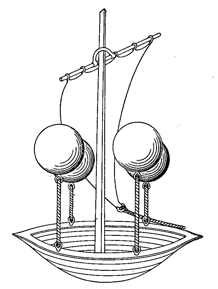
Fig. 1. De Lana Airboat.
Early Attempts. Leonardo da Vinci devoted some time to the problem of artificial flight. His sketches show the details of batlike wings which were to spread out on the downward stroke and fold up with the upward stroke.
Francisco de Lana planned to make a flying ship the appearance of which was somewhat like that shown in Fig. 1, by exhausting the air from metal spheres fastened to a boat. The boat was to be equipped with oars and sails for propulsion and guiding. The method in which he purposed to create the vacuum in the spheres consisted of filling them with water, thus driving out the air, then letting the water run out. He thought that if he closed the tap at the proper time, there would be neither air nor water in the spheres. His flying ship was never constructed, for he piously decided that God would never permit such a change in the affairs of men.
The First Flying Machine. In 1781, Meerwein of Baden, Germany, constructed a flying machine, and was the first, perhaps, to intelligently take into account the resistance of the air. He took the wild duck as a basis of calculation, and found that a man and machine weighing together 200 pounds would require a wing surface of from 125 to 130 square feet. It is of interest to note that Lilienthal, who met his death in trying to apply these principles, over one hundred years later found these figures to be correct. Two views of Meerwein’s apparatus are shown in Fig. 2. The construction involved two wood frames covered with cloth. The machine weighed 56 pounds and had a surface area of 111 square feet. The operator was fastened in the middle of the under side of the wings, and over a rod by which he worked the wings. His attempts at flight were not successful, as his ideas of the power of a man were in error.
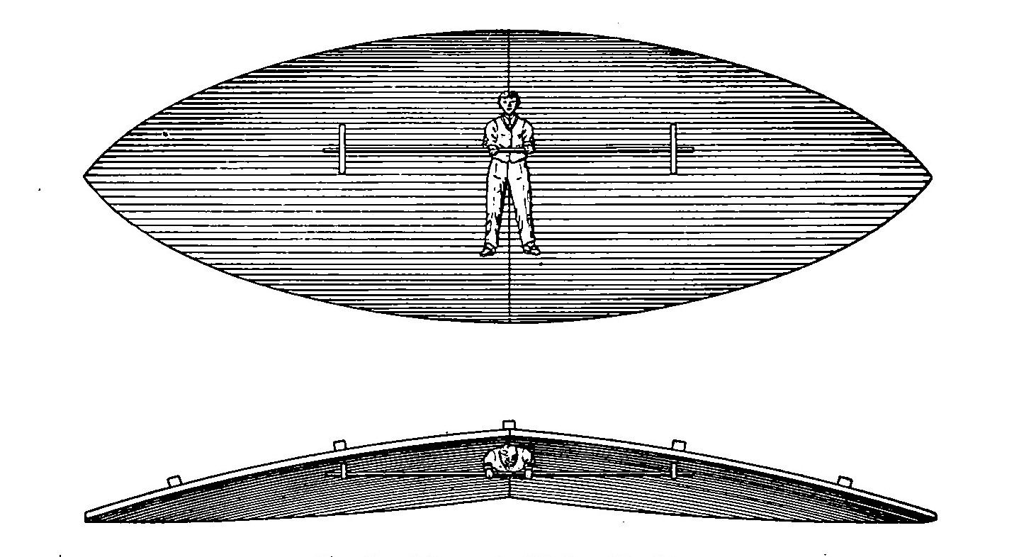
Fig. 2. Meerwein Flying Machine
Classification. All attempts at human flight have gone to show that there are four possible ways in which man may hope to navigate the air. He may imitate the flight of birds with a machine with moving or flapping wings; he may use vertical screws or helices to pull himself up; he may use an aeroplane and sail the air like an eagle; or, lastly, he may raise himself by means of a gas bag and either drift with the wind or move forward by means of propellers.
In these attempts, apparatus of several different types has been developed. The types are classed in two general divisions based on their weight relative to that of the atmosphere, viz, the lighter-than-air machines and the heavier-than-air machines. Lighter-than-air machines are those which employ a bag filled with a gas whose specific gravity is sufficiently less than that of the air to lift the bag and the necessary attachments from the earth, and include simple balloons and dirigibles. Heavier-than-air machines, which will neither rise nor remain in the air without motive power, include all forms of aeroplanes.
SIMPLE BALLOONS
Theory. The balloon-like airship has been more highly developed than any other type of aerial craft, probably because it offers the most obvious means of overcoming the force of gravitation. It depends on the law of Archimedes:
"Every body which is immersed in a fluid is acted upon by an upward force, exactly equal to the weight of the fluid displaced by the immersed body."
That is, a body will be at rest if immersed in a fluid of equal specific gravity or equal weight, volume for volume; if the body has less specific gravity than the fluid in which it is immersed it will rise; if it has a greater specific gravity it will sink. Therefore, if the total weight of a balloon is less than the weight of all the air it displaces it will rise in the air. It is, then, necessary to fill the balloon with some gas whose specific gravity is enough less than, that of the air to make the weight of the gas itself, the bags, and the attachments, less than the weight of the air displaced by the whole apparatus. The gases usually employed are hydrogen, coal gas, and hot air.
At atmospheric pressure and freezing temperature, the weight of a cubic foot of air is about .08 pound; the weight of a cubic foot of hydrogen is about .005 pound, under the same conditions. According to the law of Archimedes, a cubic foot of hydrogen would be acted upon by a force equal to the difference, or approximately .075 pound, tending to move it upwards. In the same way, a cubic foot of coal gas, which weighs .04 pound, would be acted upon by an upward force of .04 pound.
It is evident, then, that a considerable volume of gas is required to lift a balloon with its envelope, net, car, and other attachments.
Further, it requires almost twice as much coal gas as hydrogen, under the same conditions, for we have seen that the upward force on it is only half as great. The lifting power of hot air is less than one-eighth as great as that of hydrogen at the highest temperature that can possibly be used in a balloon.
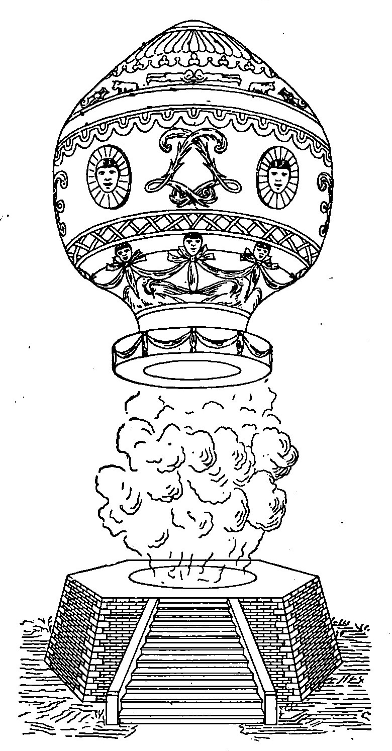
Fig. 3. Montgolfier Balloon
The general type of lighter-than-air machines may be divided into aerostats (ordinary balloons, which are entirely dependent on wind currents for lateral movement, and which are often the chief features at country fairs) and dirigible balloons or aeronats (air swimmers). Dirigible balloons employ the gas bag for maintaining buoyancy, and have rudders to guide them and propellers to drive them forward through the air in much the same way that ships are driven through the water.
The First Balloon. For several years, Joseph and Steven Montgolfier had been experimenting with a view to constructing a balloon: in the first place by filling bags with steam; then by filling bags with smoke, and finally by filling bags with hydrogen. These attempts were all failures, for the steam rapidly condensed and the smoke and hydrogen leaked through the pores in the bags. They finally hit upon the idea of filling the bag with hot air, by means of a fire under its open mouth. Several balloons were burned up, but the next was always made larger, until, at their first public exhibition on June 5, 1783, the bag had become over 35 feet in diameter. On this occasion, it rose to a height of between 900 and 1,000 feet, but the hot air was gradually escaping, and at the end of ten minutes the balloon fell to the ground.
The Montgolfiers then went to Paris, where, after suffering the loss of a paper balloon by rain, they sent up a waterproofed linen one carrying a sheep, a duck, and a rooster in a basket. A rupture in the linen caused the three unwilling aeronauts to make a landing at the end of about ten minutes. The Montgolfiers received great honor, and small balloons of this type became a popular fad. One of these balloons is shown in Fig. 3, making an ascension.
Rozier. The first man to go up in a balloon was Rozier, who ascended in a captive balloon to a height of about 80 feet, in the latter part of the year 1783. Later, in company with a companion, he made a voyage in a free balloon, remaining in the air about half an hour. In these balloons, the air within was kept hot by means of a fire carried in a pan immediately below the mouth of the bag, as shown in Fig. 4. Accidents were numerous on account of the fabric becoming ignited from the fire in the pan.
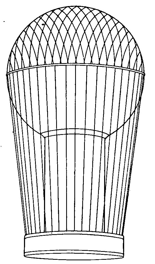
Fig. 4. Rozier Hot-Air Balloon
Improvements by Charles. The physicist, Charles, was working along these lines at the same time. He coated his balloon with a rubber solution to close up the pores, and was thereby enabled to substitute hydrogen for the hot air. Shortly after the Montgolfiers’ first public exhibition, Charles sent up his balloon for the benefit of the Academie des Sciences in Paris. The balloon, which weighed about 19 pounds, ascended rapidly in the air and disappeared in the clouds, where it burst and fell in a suburb of the city. The impression produced upon the peasants at seeing it fall from the heavens was hardly different from what could be expected. They believed it to be of devilish origin, and immediately tore it into shreds. Charles subsequently built a large balloon quite similar to those in use today. A net was used to support the basket, and a valve, operated by means of ropes from the basket, was arranged at the top to permit the gas to escape as desired.
The Balloon Successful. The English Channel was first crossed in 1785. Blanchard, an Englishman, and Jeffries, an American, started from Dover on January 7 in a balloon equipped with wings and oars. After a very hazardous voyage, during which they had to cast overboard everything movable to keep from drowning, they landed in triumph on the French coast.
An attempt to duplicate this feat was made shortly afterward by Rozier. He constructed a balloon filled with hydrogen, below which hung a receiver in which air could be heated. He hoped to replace by the hot air the losses due to leakage of hydrogen. Soon after the start the balloon exploded, due to the escaping gas reaching the fire, and Rozier and his companion were dashed on the cliffs and killed.
EARLY DIRIGIBLES
Meusnier the Pioneer. The fact that the invention of the dirigible balloon and means of navigating it were almost simultaneous is very little known today and much less appreciated. Like the aeroplane, its development was very much retarded by the lack of suitable means of propulsion, and the actual history of what has been accomplished in this field dates back only to the initial circular flight of La France in 1885. Still the principles upon which success has been achieved were laid down within a year of the appearance of Montgolfier’s first gas bag. Lieutenant Meusnier, who subsequently became a general in the French army, must really be credited with being the true inventor of aerial navigation. At a time when nothing whatever was known of the science, Meusnier had the distinction of elaborating at one stroke all the laws governing the stability of an airship, and calculating correctly the conditions of equilibrium for an elongated balloon, after having strikingly demonstrated the necessity for this elongation. This was in 1781 and Meusnier’s designs and calculations are still preserved in the engineering section of the French War Office in the form of drawings and tables.
But as often proved to be the case in other fields of research, his efforts went unheeded. How marvelous the establishment of these numerous principles by one man in a short time really is, can be appreciated only by noting the painfully slow process that has been necessary to again determine them, one by one, at considerable intervals and after numerous failures. Through not following the lines which he laid down, aerial navigation lost a century in futile groping about; in experiments absolutely without method or sequence.
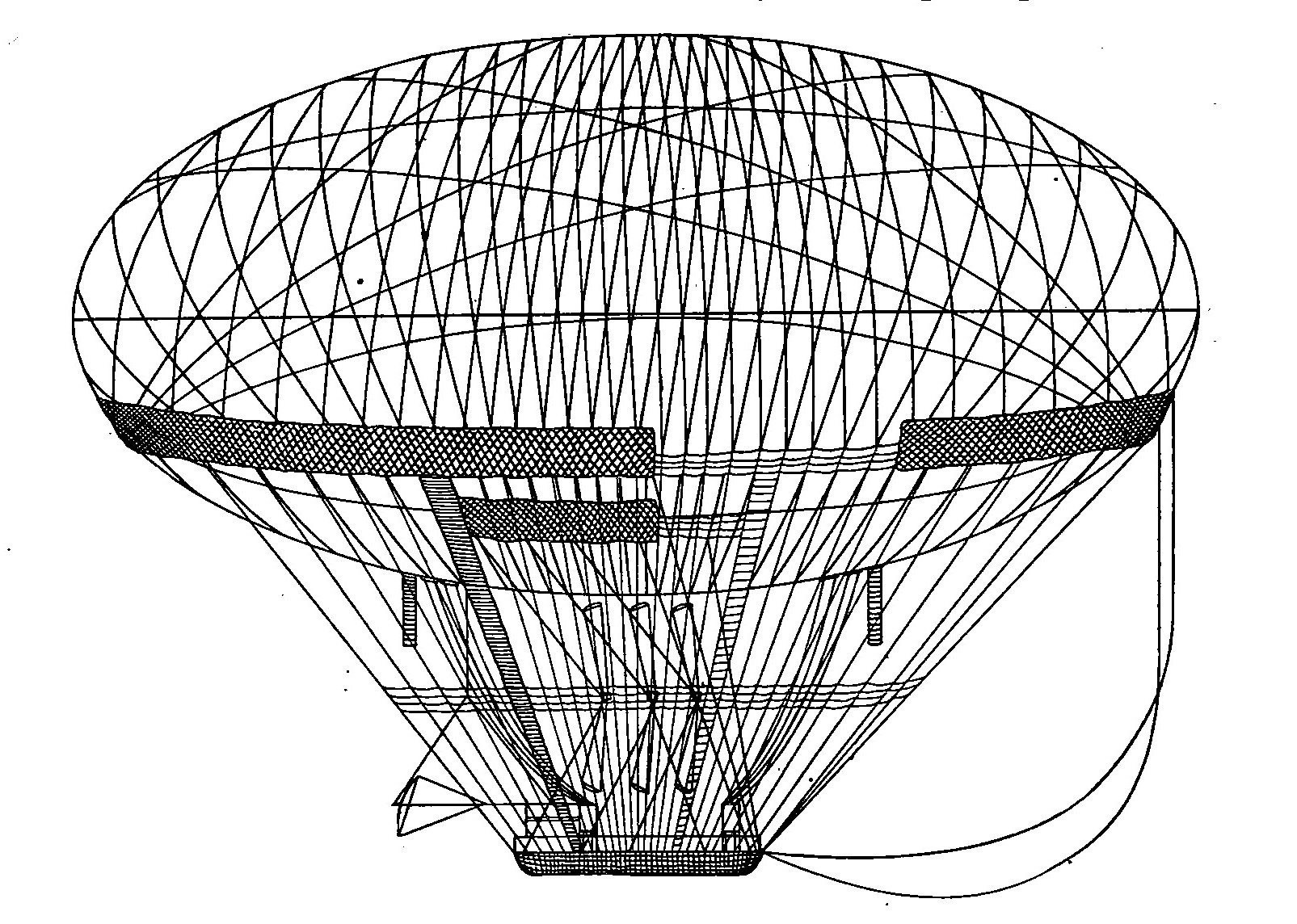
Fig. 5. Meusnier Dirigible Balloon
Meusnier’s designs covered two dirigible balloons and that he fully appreciated the necessity for size is shown by the dimensions of the larger, which unfortunately was never built. This was to be 260 feet long by 130 feet in diameter, in the form of an ellipse, the elongation being exactly twice the diameter. In other words, a perfect ellipsoid, which was a logical and, in fact, the most perfect development of the spherical form. Although increased knowledge of wind resistance and the importance of the part it plays has proved his relative dimensions to be faulty, a study of the principal features of his machine shows that he anticipated the present-day dirigible of the most successful type at practically every point, barring, of course, the motive power, as there was absolutely nothing available in that day except human effort. As the latter weighs more than one-half ton per horse-power, it goes without saying that Meusnier’s balloon would have been dirigible only in a dead calm.
He adopted the elongated form, conceived the girth fastening, the triangular or indeformable suspension, the air balloonet and its pumps, and the screw propeller, all of which are to be found in the dirigibles of present-day French construction, Fig. 5. It need scarcely be added that the French have not only devoted a greater amount of time and effort to the development of the dirigible than any other nation, but have also met with the greatest success in its use. It was not until 1886, or more than a century after Meusnier had first elaborated those principles, that their value became known. They were set forth by Lieutenant Letourne, of the French engineers, in a paper presented to the Academie des Sciences by General Perrier.
In one form or another, the salient features of Meusnier’s dirigible will be found embodied in the majority of attempts of later days. His large airship was designed to consist of double envelope, the outer container of which was to provide the strength necessary, and it was accordingly reinforced by bands. The inner envelope was to provide the container for the gas and was not called upon to support any weight. This inner bag or balloon proper was designed to be only partially inflated and the space between, the two was to be occupied by air which could be forced into it at two points at either end, by pumps, so as to maintain the pressure on the gas bag uniform regardless of the expansion or contraction of its contents. Here in principle was the air balloonet of today. Instead of employing a net to hang the car from the outer envelope, the former was attached by means of a triangular suspension system fastened to a heavy rope band, or girth, encircling the outer envelope. At the three points where the lifting rope members met, a shaft running the length of the car and carrying what Meusnier described as "revolving oars" was installed. These constituted the prototype of the screw propeller, invented for aerial navigation at a time long antedating the use of steam for marine use. Thus he devised: (1) The air balloonet to husband the gas supply and thus prevent the deformation of the outer container or support, as well as to provide stability; (2) the triangular suspension to attain longitudinal stability; and (3) the screw propeller for propulsion, beside selecting the proper location for the latter.
PROBLEMS OF THE DIRIGIBLE
Ability to Float. If ability to rise in the air depended merely upon a knowledge of the principle that made it possible, it undoubtedly would have been accomplished many centuries ago. As already mentioned, Archimedes established the fact that a body upon floating in a fluid displaces an amount of the latter equal in weight to the body itself, and upon this theory was formulated the now well-known law, that every body plunged into a fluid is subjected by this fluid to a pressure from below, equivalent to the weight of the fluid displaced by the body. Consequently, if the weight of the latter be less than that of the fluid it displaces, the body will float. It is by reason of this that the iron ship floats and the fish swims in water. If the weight of the body and the displaced water be the same, the body will remain in equilibrium in the water at a certain level, and if that of the body be greater, it will sink. All three of these factors are found in the fish, which, with the aid of its natatory gland, can rise to the surface, sink to the bottom, or remain suspended at different levels. To accomplish these changes of specific gravity, the fish fills this gland with air, dilating it until full, or compressing and emptying it. In this we find a perfect analogy to the air balloonet of the dirigible, which serves the same purposes. The method by which lifting power is obtained in the dirigible is exactly the same as in the case of the balloon.
But once in the air, a balloon is, to all intents and purposes, a part of the atmosphere. There is absolutely no sensation of movement, either vertically or horizontally. The earth appears to drop away from beneath and to sweep by horizontally, and regardless of how violently the wind may be blowing, the balloon is always in a dead calm because it is really part of the wind itself and is traveling with it at exactly the same speed. If it were not for the loss of lifting power through the expansion and contraction of the gas, making it necessary to permit its escape in order to avoid rising to inconvenient heights on a very warm day, and the sacrifice of ballast to prevent coming to earth at night, the ability of a balloon to stay up would be limited only by the endurance of its crew and the quantity of provisions it was able to transport. As the use of air balloonets in the dirigible takes care of this, the question of lifting power presents no particular difficulty. It is only a matter of providing sufficient gas to support the increased weight of the car, motor and its accessories, and the crew of the larger vessel, with a factor of safety to allow for emergencies, in order to permit of staying in the air long enough to make a protracted voyage.
Air Resistance vs. Speed. Unless a voyage is to be governed in its direction entirely by the wind, the dirigible must possess a means of moving contrary to the latter. The moment this is attempted, resistance is encountered, and it is this resistance of the air that is responsible for the chief difficulties in the design of the dirigible. To drive it against the wind, it must have power; to support the weight of the motor necessary, the size of the gas bag must be increased. But with the increase in size, the amount of resistance is greatly multiplied and the power to force it through the air must be increased correspondingly. The law is approximately as follows:
Where the surface moves in a line perpendicular to its plane, the resistance is proportional to the extent of the surface, to the square of the speed with which the surface is moved through the air, and to a coefficient, the mean value of which is 0.125.
This coefficient is a doubtful factor, the figure given having been worked out years ago in connection with the propulsion of sailing vessels. Its value varies according to later experimenters between .08 and .16, the mean of the more recent investigations of Renard, Eiffel, and others who have devoted considerable study to the matter, being .08. This is dwelt upon more in detail under "Aerodynamics" and it will be noted that the values of the coefficient K, given here, do not agree with those stated in that article. They serve, however, to illustrate the principles in question.
In accordance with this law, doubling the speed means quadrupling the resistance of the air. For instance, a surface of 16 square feet moving directly against the air at a speed of 10 feet per second will encounter a resistance of 16 X 100 (square of the speed) X 0.125 = 200 pounds pressure. Doubling the speed, thus bringing it up to 20 feet per second, would give the equation 16 X 400 X 0.125 = 800 pounds pressure, or with the more recent value of the coefficient of .08, 512 pounds pressure. The first consideration is accordingly to reduce the amount of surface moving at right angles. The resistance of a surface having tapering sides which cut through or divide the molecules of air instead of allowing them to impinge directly upon it, is greatly diminished; hence, Meusnier’s principle of elongation. If we take the same panel presenting 16 square feet of surface and build out on it a hemisphere, its resistance at a speed of 10 feet per second will be exactly half, or a pressure of 100 pounds.
By further modifying this so as to represent a sharp point, or acute-angled cone, it will be 38 pounds. There could accordingly be no question of attempting to propel a spherical balloon.
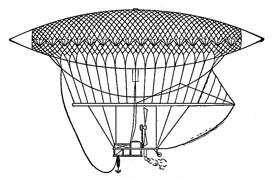
Fig. 6. Giffard Dirigible
It is necessary to select a form that presents as small a surface as possible to the air as the balloon advances, while preserving the maximum lifting power. But experience has strikingly demonstrated the analogy between marine and aerial practice—not only is the shape of the bow of the vessel of great importance but, likewise, the stern. The profile of the latter may permit of an easy reunion of the molecules of air separated by the former, or it may allow them to come together again suddenly, clashing with one another and producing disturbing eddies just behind the moving body. To carry the comparison with a marine vessel a bit further, the form must be such as to give an easy "shear," or sweep from stem to stern.
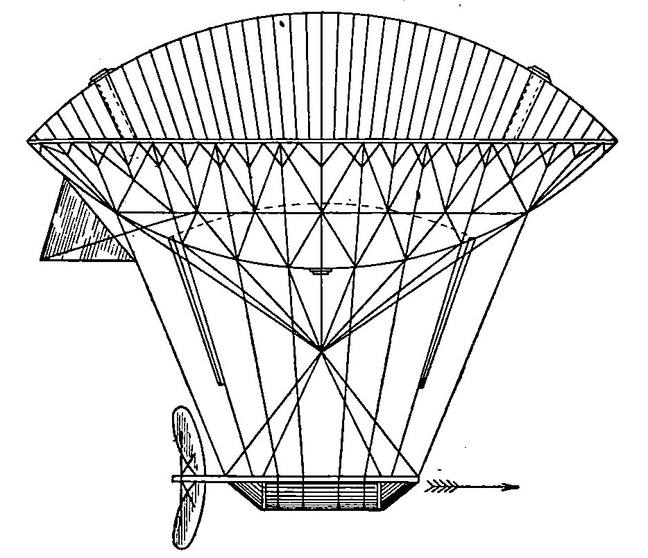
Fig. 7. De Lome Dirigible
That early investigators appreciated this is shown by the fact that Giffard in 1852, Fig. 6, De Lome in 1872, Fig. 7, Tissandier in 1884, and Santos-Dumont in his numerous attempts, adopted a spindle-shaped or "fusiform" balloon. In other words, their shape, equally pointed at either end, was symmetrical in relation to their central plan. However, that the shape best adapted to the requirements of the bow did not serve equally well for the stern, was demonstrated for the first time by Renard, to whom credit must be given for a very large part of the scientific development of the dirigible. Almost a century earlier, Marey-Monge had laid down the principle that to be successfully propelled through the air, the balloon must have "the head of a cod and the tail of a mackerel." Nature exemplifies the truth of this in all swiftly moving fishes and birds. Renard accordingly adopted what may best be termed the "pisciform" type, viz, that of a dis-symmetrical fish with the larger end serving as the bow; and the performances of the Renard, Lebaudy, and Clement-Bayard airships have shown that this is the most advantageous form.
The pointed stern prevents the formation of eddies and the creation of a partial vacuum in the wake which would impose additional thrust on the bow. Zeppelin has disregarded this factor by adhering to the purely cylindrical form with short hemispherical bow and stern, but it is to be noted that while other German investigators originally followed this precedent, they have gradually abandoned it, owing to the noticeable retarding effect.
Critical Size of Bag. Next in importance to the best form to be given the vessel, is the most effective size—something which has a direct bearing upon its lifting power. This depends upon the volume, while the resistance is proportional to the amount of surface presented. Greater lifting power can accordingly be obtained by keeping the diameter down and increasing the length. But the resistance is also proportionate to the square of the speed, while the volume, or lifting power, varies as the cube of the dimensions of the container, so that in doubling the latter, the resistance of the vessel at a certain speed is increased only four times while its lifting capacity is increased eight times. Consequently the larger dirigible is very much more efficient than the smaller one since it can carry so much more weight in the form of a motor and fuel in proportion to its resistance to the air. As an illustration of this, assume a rectangular container with square ends 1 foot each way and 5 feet long. Its volume will be 5 cubic feet and if the lifting power of the gas be assumed as 2 pounds per cubic foot, its total lifting power will be 5 pounds. If a motor weighing exactly 5 pounds per horse-power be assumed, it will be evident that the motor which such a balloon could carry would be limited to 1 horse-power, neglecting the weight of the container.
Double these dimensions and the container will then measure 2 X 2 X 10 feet, giving a volume of 40 cubic feet, and a lifting power, on the basis already assumed, of a motor capable of producing 8 horsepower, and this without taking into consideration that as the size of the motor increases, its weight per horse-power decreases. The balloon of twice the size will thus have a motor of 8 horse-power to overcome the resistance of the head-on surface of 4 square feet, or 2 horse-power per square foot of transverse section, whereas the balloon of half the size will have only 1 horse-power per square foot of transverse section. It is, accordingly, not practicable to construct small dirigibles such as the various airships built by Santos-Dumont for his experiments, while, on the other hand, there are numerous limitations that will be obvious, restricting an increase in size beyond a certain point, as has been shown by the experience of the various Zeppelin airships.
To make it serviceable, what Berget terms the "independent speed" of a dirigible, i.e., its power to move itself against the wind, must be sufficient to enable it to travel under normally prevailing atmospheric conditions. These naturally differ greatly in different countries and in different parts of the same country. Where meteorological tables showed the prevailing winds in a certain district to exceed 15 miles an hour throughout a large part of the year, it would be useless to construct an airship with a speed of 15 miles an hour or less for use in that particular district, as the number of days in the year in which one could travel to and from a certain starting point would be limited. This introduces another factor which has a vital bearing upon the size of the vessel. Refer to the figures just cited and assume further that by doubling the dimensions and making the airship capable of transporting a motor of 8 horse-power, it has a speed of 10 miles an hour. It is desired to double this. But the resistance of the surface presented increases as the square of the speed. Hence, it will not avail merely to double the power of the motor. Experience has demonstrated that the power necessary to increase the speed of the same body, increases in proportion to the cube of the speed, so that instead of a 16-horse-power motor in the case mentioned, one of 64 horse-power would be needed. There are, accordingly, a number of elements that must be taken into consideration when determining the size as well as the shape of the balloon.
Static Equilibrium. Having settled upon the size and shape, there must be an appropriate means of attaching the car to carry the power plant, its accessories and control, and the crew. While apparently a simple matter, this involves one of the most important elements of the design—that of stability. A long envelope of comparatively small diameter being necessary for the reasons given, it is essential that this be maintained with its axis horizontal. In calm air, the balloon, or container, is subjected to the action of two forces: One is its weight, applied to the center of gravity of the system formed by the balloon, its car, and all the supports; the other is the thrust of the air, applied at a point known as the center of thrust and which will differ with different designs, according as the car is suspended nearer or farther away from the balloon. If the latter contained only the gas used to inflate it, with no car or other weight to carry, the center of gravity and the center of thrust would coincide, granting that the weight of the envelope were negligible. As this naturally can not be the case, these forces are not a continuation of each other. But as they must necessarily be equal if the balloon is neither ascending nor descending, it follows that they will cause the balloon to turn until they are a continuation of each other, and in the case of a pisciform balloon, this will cause it to tilt downward. Like a ship with too much cargo forward, it would be what sailors term "down at the head."
As this would be neither convenient nor compatible with rapid propulsion, it must be avoided by distributing the weight along the car in such a manner that when the balloon is horizontal, the forces represented by the pressure above and the weight below, must be in the same perpendicular. This is necessary to insure static equilibrium, or a horizontal position while in a state of rest. To bring this about, the connections between the car and the balloon must always maintain the same relative position, which is further complicated by the fact that they must be flexible at the same time.
Longitudinal Stability. But the longitudinal stability of the airship as a whole must be preserved, and this also involves its stability of direction. Its axis must be a tangent to the course it describes, if the latter be curvilinear, Or parallel with the direction of this course where the course itself is straight. This is apparently something which should be taken care of by the rudder, any tendency on the part of the airship to diverge from its course being corrected by the pilot. But a boat that needed constant attention to the helm to keep it on its course would be put down as a "cranky"—in other words, of faulty design in the hull. A dirigible having the same defect would be difficult to navigate, as the rudder alone would not suffice to correct this tendency in emergencies. Stability of direction is, accordingly, provided for in the design of the balloon itself, and this is the chief reason for adopting the form of a large-headed and slender-bodied fish, as already outlined. This brings the center of gravity forward and makes of the long tail an effective lever which overcomes any tendency of the ship to diverge from the course it should follow, by causing the resistance of the air itself to bring it back into line. However, the envelope of the balloon itself would not suffice for this, so just astern of the latter, "stabilizing surfaces" are placed, consisting of vertical planes fixed to the envelope. These form the keel of the dirigible and are analogous to the keel of the ship. Stability of direction is thus obtained naturally without having constant recourse to the rudder, which is employed only to alter the direction of travel.
The comparison between marine and aerial navigation must be carried even further. These vertical planes, or "keel," prevent rolling; it is equally necessary to avoid pitching—far more so than in the case of a vessel in water. So that while the question of stability of direction is intimately connected with longitudinal stability, other means are required to insure the latter. The airship must travel on an "even keel," except when ascending or descending, and the latter must be closely under the control of the pilot, as otherwise the balloon may incline at a dangerous angle. This shows the importance of an unvarying connection between the car and the envelope to avoid defective longitudinal stability. Assume, for instance, that the car is merely attached at each end of a single line. The car, the horizontal axis of the balloon, and the two supports would then form a rectangle. When in a state of equilibrium the weight and the thrust are acting in the same line. Now suppose that the pilot desires to descend and inclines the ship downward. The center of gravity is then shifted farther forward and the two forces are no longer in line.
But as the connections permit the car to swing in a vertical plane, they permit the latter to move forward and parallel with the balloon, thus forming a parallelogram instead of a rectangle. This causes the center of gravity to shift even farther, and as one of the most serious causes of longitudinal stability is the movement of the gas itself, it would also rush to the back end and cause the balloon to "stand on its head." As the tendency of the gas is thus to augment any inclination accidentally produced, the vital necessity of providing a suspension that is incapable of displacement with relation to the balloon is evident. Here is where the importance of Meusnier’s conception of the principle of triangular suspension comes in. Instead of being merely supported by direct vertical connections with the balloon, the ends of the car are also attached to the opposite ends of the envelope, forming opposite triangles. This gives an unvarying attachment, so that when the balloon inclines, the car maintains its relative position, and the weight and thrust tend to pull each other back in the same line, or, in other words, to "trim ship."
Dynamic Equilibrium. In addition to being able to preserve its static equilibrium and to possess proper longitudinal stability, the successful airship must also maintain its dynamic equilibrium—the equilibrium of the airship in motion. This may be made clear by referring to the well-known expedients adopted to navigate the ordinary spherical balloon. To rise, its weight is diminished by gradually pouring sand from the bags which are always carried as ballast. To descend, it is necessary to increase the total weight of the balloon and its car, and the only method of accomplishing this is to permit the escape of some of the gas, the specific lightness of which constitutes the lifting power of the balloon. As the gas escapes, the thrust of the air on the balloon is decreased and it sinks—the ascensional effort diminishing in proportion to the amount of gas that is lost. The balloon, or the container itself, being merely a spherical bag, on the upper hemispherical half of which the net supporting the car presses at all points, the question of deformation is not a serious one. Before it assumed proportions where the bag might be in danger of collapsing, the balloon would have had to come to earth through lack of lifting power to longer sustain it. Owing to its far greater size, as well as to the form of the surface which it presents to the air pressure, such a crude method is naturally not applicable to the dirigible.
Dynamic equilibrium must take into account not only its weight and the sustaining pressure of the air, but also the resistance of the air exerted upon its envelope. This resistance depends upon the dimensions and the shape of that envelope, and in calculations the latter is always assumed to be invariable. Assume, for instance, that to descend the pilot of a dirigible allowed some of the hydrogen gas to escape. As the airship came down, it would have to pass through strata of air of constantly increasing pressure as the earth is approached. The reason for this will be apparent as the lower strata bear the weight of the entire atmosphere above them. The confined gas will no longer be sufficient to distend the envelope, the latter losing its shape and becoming flabby. As the original form is no longer retained, the center of resistance of the air will likewise have changed together with the center of thrust, and the initial conditions will no longer obtain. But as the equilibrium of the airship depends upon the maintenance of these conditions, it will be lost if they vary.
Function of Balloonets. In the function of balloonets is realized the importance of the principle established by Meusnier. It was almost a century later before it was rediscovered by Dupuy de Lome in connection with his attempts to make balloons dirigible. That the balloon must always be maintained in a state of perfect inflation has been pointed out. But gas is lost in descents and to a certain extent, through the permeability of the envelope. Unless it is replaced, the balloon will be only partially inflated. In view of the great volume necessary, it requires no explanation to show that it would be impossible to replace the gas itself by fresh hydrogen carried on the car. It would have to be under high pressure and the weight of the steel cylinders as well as the number necessary to transport a sufficient supply would be prohibitive. Hence, Meusnier conceived the idea of employing air. But this could not be pumped directly into the balloon to mix with the hydrogen gas, as the resulting mixture would not only still be as inflammable as the former alone, but it would also contain sufficient oxygen to create a very powerful and infinitely more dangerous explosive. This led to the adoption of the air balloonet.
In principle the balloonet consists of dividing the interior of the envelope into two cells, the larger of which receives the light gas while the smaller is intended to hold air and terminates in a tube extending down to a pump in the car. In other words, a fabric partition adjacent to the lower part of the envelope inside and subject to deformation at will. In actual practice it consists of a number of independent cells of this kind, longitudinally disposed along the lower half of the interior of the envelope.
When the balloon is completely inflated with hydrogen, as at the beginning of an ascent, these balloonets lie flat against the lower part of the envelope, exactly like a lining. As the airship rises, the gas expands owing to the reduction in atmospheric pressure at a higher altitude, as well as to the influence of heat. With the increase in pressure, uniform inflation is maintained by the escape of a certain amount of gas through the automatic valves provided for the purpose. Unless this took place, the internal pressure might assume proportions placing the balloon in danger of blowing up. To avoid this, a pressure gauge communicating with the gas compartment is one of the most important instruments on the control board of the car, and should its reading indicate a failure of the automatic valves, the pilot must reduce the pressure by operating a hand valve. But as the car descends, the increased external pressure causes a recontraction of the gas until it no longer suffices to fill the envelope. To replace the loss the air pumps are utilized to force air into the air balloonets until the sum of the volumes of gas and air in the different compartments equals the original volume. In this manner, the initial conditions, upon which the equilibrium of the airship is based, are always maintained.
This is not the only method of correcting for change in volume, nor of maintaining the longitudinal stability of the whole fabric, the importance of which has already been detailed, but experience has shown that it is the most practical. It is possible to give the balloon a rigid frame over which the envelope is stretched and to attach the car by means of a rigid metal suspension, as in the various Zeppelin airships, or to take it semi-rigid, as in the Gross, another German type in which Zeppelin’s precedent was followed only in the case of the suspension. To prevent deformation by this means, the balloon is provided with an absolutely rigid skeleton of aluminum tubes. This framing is in the shape of a number of uniform cylindrical sections, or gas compartments, each one of which accommodates an independent balloon, while over the entire frame a very strong but light fabric constituting the outer or protecting envelope is stretched taut. The idea of the numerous independent balloons is to insure a high factor of safety as the loss of the entire contents of two or three of them through accident would not dangerously affect the lifting power of the whole. The numerous wrecks which attended the landings of these huge non-flexible masses during the early stages of their development led to the provision of some form of shelter wherever they were expected to land. Even now, they are practically unmanageable in the air during a fierce wind and must be allowed to sail under control until the wind has spent itself.
The system of air balloonets has accordingly been adopted by every other designer, in variously modified forms, as illustrated by the German dirigible Parseval, in which but two air bags were employed, one at either end. They were interconnected by an external tube to which the air-pump discharge was attached, and were also operated by a counterbalancing system inside the gas bag, by means of which the inflation of one balloonet, as the after one, for example, caused the collapse of the other.
Influence of Fish Form of Bag. But a condition of dynamic equilibrium can not be obtained with the combined aid of the precautions already noted to secure longitudinal stability and that of the air balloonet in maintaining uniform inflation. Why this is so will be clear from a simple example. If a simple fusiform or spindle-shaped balloon be suspended in the air in a horizontal plane, the axis of which passes through its center of gravity, it would be practically pivoted on the latter and would be extremely sensitive to influences tending to tilt it up or down. It would be in a state of "indifferent" longitudinal equilibrium. As long as the axis of the balloon remains horizontal and the air pressure is coincident with that axis, it will be in equilibrium, but an equilibrium essentially unstable. Experiment proves that the moment the balloon inclines from the horizontal in the slightest degree, there is a strong tendency for it to revolve about its center of gravity until it stands vertical to the air current, or is standing straight up and down. This, of course, refers to the balloon alone without any attachments. Such a tendency would be fatal, amounting as it does to absolute instability.
If instead of symmetrical form, tapering toward both ends, a pisciform balloon be tried, it will still evidence the same tendency, but in greatly diminished degree. This is not merely the theory affecting its stability but represents the findings of Col. Charles Renard, who undoubtedly did more to formulate the exact laws governing the stability of a dirigible than any other investigator in this field. His data is the result of a long and methodically carried out series of experiments. In the case of the pisciform balloon, the disturbing effect is due in unequal degree, to the diameter of the balloon and its inclination and speed, whereas the steadying effect depends upon the inclination and diameter, but not on the Speed. The disturbing effect, therefore, depends solely on the speed and augments very rapidly as the speed increases. It will, accordingly, be apparent that there is a certain speed for which the two effects are equal, and beyond which the disturbing influence, depending on speed, will overcome the steadying effect.
To this rate of travel, Renard applied the term "critical speed," and when this is exceeded the equilibrium of the balloon becomes unstable. To obtain this data, keels of varying shapes and dimensions were submitted to the action of a current of air, the force of which could be varied at will. In the case of the La France, the first fish-shaped dirigible, the critical speed was found to be 10 meters, or approximately 39 feet per second, a speed of 21.6 miles per hour, and a 24-horse-power motor suffices to drive the airship at this rate of travel. But the internal combustion motor is now so light that a dirigible of this type could easily lift a motor capable of generating 80 to 100 horse-power. With this amount of power, its theoretic speed would be 50 per cent greater, or 33 miles an hour. But this could not be accomplished in practice as long before it was reached the stability would become precarious. As Colonel Renard observed in the instance just cited, "If the balloon were provided with a 100-horse-power motor, the first 24 horse-power would make it go and the other 76 horse-power would break our necks."
Steadying Planes. It is accordingly necessary to adopt a further expedient to insure stability. This takes the form of a system of rigid planes, both vertical and horizontal, located in the axis of the balloon and placed a considerable distance to the rear of the center of gravity. With this addition, the resemblance of the after end of the balloon to the feathering of an arrow is apparent, while its purpose is similar to that of the latter. For this reason, these steadying planes have been termed the empennage, which is the French equivalent of "arrow feathering," while its derivative empennation is employed to describe the counteraction of this disturbing effect. In the La France, which measured about 230 feet in length by 40 feet in diameter, the area of the planes required to accomplish this was 160 square feet, and the planes themselves were placed almost 100 feet to the rear of the center of gravity. By referring to the illustrations of the various French airships, the various developments in the methods of accomplishing this will be apparent.
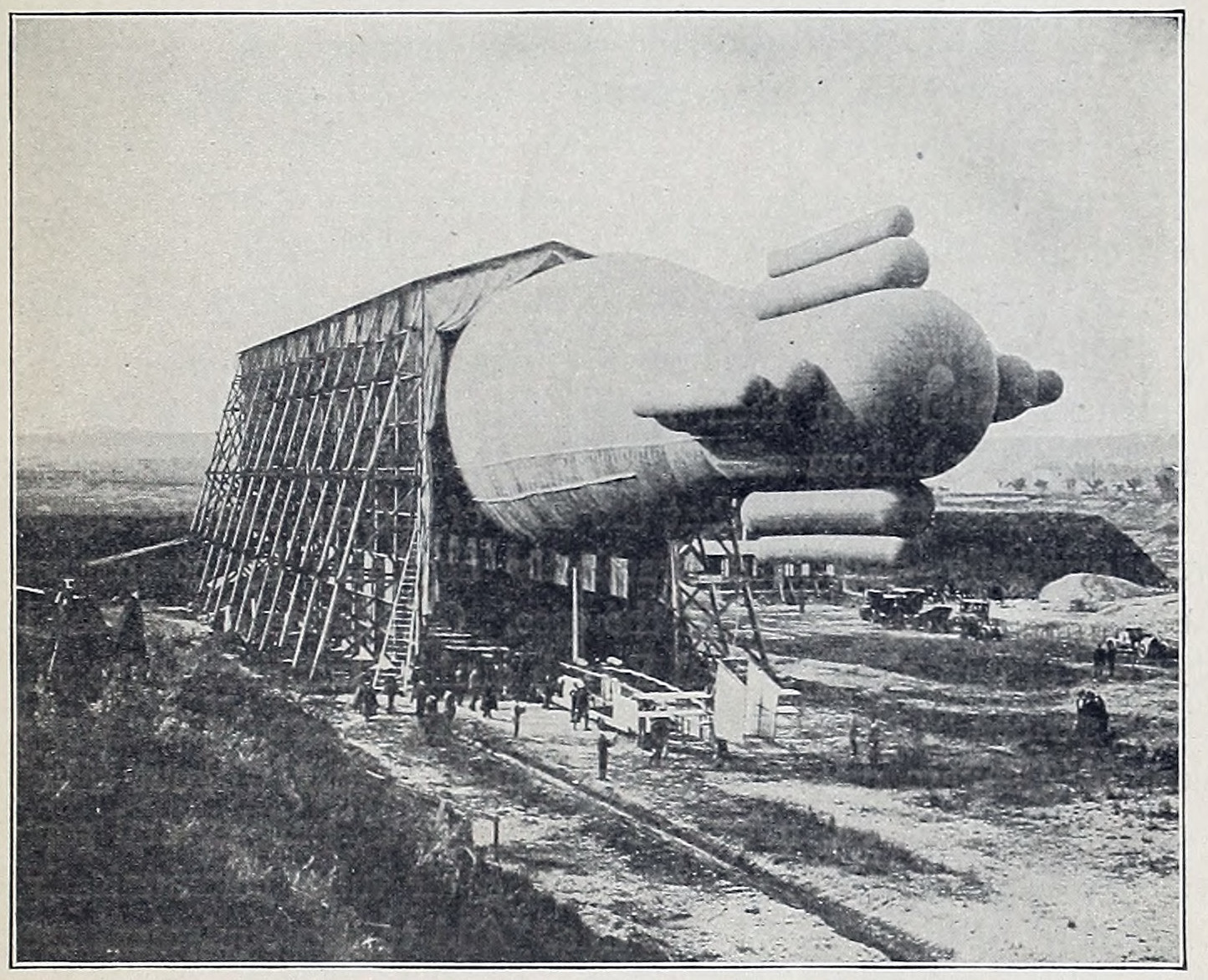
Fig. 8. La Ville de Paris Showing Balloonets
In the Lebaudy balloon, it took the form of planes attached to the framework between the car and the balloon. In La Patrie and La Republique, the resemblance to the feathered arrow was completed by attaching four planes in the form of a cross directly to the stern of the balloon itself. But as weight, no matter how slight, is a disturbing factor at the end of a long lever, such as is represented by the balloon, Renard devised an improvement over these methods by conceiving the use of hydrogen balloonets as steadying planes. The idea was first embodied in La Ville de Paris, Fig. 8, in the form of cylindrical balloonets, and as conical balloonets on the Clement-Bayard. These balloonets communicate with the gas chamber proper of the balloon and consequently exert a lifting pressure which compensates for their weight, so that they no longer have the drawback of constituting an unsymmetrical supplementary load.
Location of Propeller. The final factor of importance in the design of the successful dirigible is the proper location of the propulsive effort with relation to the balloon. Theoretically, this should be applied to the axis of the balloon itself, as the latter represents the greater part of the resistance offered to the air. At least one attempt to carry this out in practice resulted disastrously, that of the Brazilian airship Pax, while the form adopted by Rose, in which the propeller was placed between the twin balloons in a plane parallel with their horizontal axes, was not a success. In theory, the balloon offers such a substantial percentage of the total resistance to the air that the area of the car and the rigging were originally considered practically negligible by comparison. Actually, however, this is not the case. Calculation shows that in the case of any of the typical French airships mentioned, the sum of the surface of the suspending rigging alone is easily the equivalent of 2 square meters, or about 21 square feet, without taking into consideration the numerous knots, splices, pulleys, and ropes employed in the working of the vessels, air tubes communicating with the air balloonets, and the like. Add to this equivalent area that of the passengers, the air pump, other transverse members and exposed surfaces, and the total will be found equivalent to a quarter or even a third of the transverse section of the balloon itself.
To insure the permanently horizontal position of the ship under the combined action of the motor and the air resistance, a position of the propeller at a point about one-third of the diameter of the balloon below its horizontal axis will be necessary. Without employing a rigid frame like that of the Zeppelin and the Pax, however, such a location of the shaft is a difficult matter for constructional reasons. Consequently, it has become customary to apply the driving effort to the car itself, as no other solution of the problem is apparent. This accounts for the tendency common in the dirigible to "float high forward," and this tilting becomes more pronounced in proportion to the distance the car is hung beneath the balloon. The term "deviation" is employed to describe this tilting effect produced by the action of the propeller. Conflicting requirements are met with in attempting to reduce this by bringing the car closer to the balloon as this approximation is limited by the danger of operating the gasoline motor too close to the huge volume of inflammable gas. The importance of this factor may be appreciated from the fact that if the car were placed too far from the balloon, the propulsive effect would tend to hold the latter at an angle without advancing much, owing to the vastly increased air resistance of the much larger surface thus presented.
Relations of Speed and Radius of Travel. The various factors influencing the speed of a dirigible have already been referred to, but it will be apparent that the radius of action is of equally great importance. It is likewise something that has a very direct bearing upon the speed and, in consequence, upon the design as a whole. It will be apparent that to be of any great value for military or other purposes, the dirigible must possess not only sufficient speed to enable it to travel to any point of the compass under ordinarily prevailing conditions of wind and weather but also to enable it to remain in the air for some time and cover considerable distance under its own power.
Total Weight per Horsepower Hour. As is the case in almost every point in the design of the dirigible, conflicting conditions must be reconciled in order to provide it with a power plant affording sufficient speed with ample radius of action. It has already been pointed out that power requirements increase as the cube of the speed, making a tremendous addition necessary to the amount of power to obtain a disproportionately small increase in velocity. In this connection there is a phase of the motor question that has not received the attention it merits up to the present time. The struggle to reduce weight to the attainable minimum has made weight per horsepower apparently the paramount consideration—a factor to which other things could be sacrificed. And this is quite as true of aeroplane motors as those designed for use in the dirigible. But it is quite as important to make the machine go as it is to make it rise in the air, so that the question of total weight per horsepower hour has led to the abandonment of extremely light engines requiring a great deal of fuel.
Speed is quite as costly in an airship as it is in an Atlantic liner. To double it, the motor power must be multiplied by 8, and the machine must carry 8 times as much fuel. But by cutting the power in half, the speed is reduced only one-fifth. The problem of long voyages in the dirigible is, accordingly, how to reconcile best the minimum speed which will enable it to make way effectively against the prevailing winds, with the reduction in power necessary to cut the fuel consumption down to a point that will insure a long period of running.
When the speed of the dirigible is greater than that of the prevailing wind, it may travel in any direction; when it is considerably less, it can travel only with the wind; when it is equal to the speed of the latter, it may travel at an angle with the wind—in other words, tack, as a ship does, utilizing the pressure of the contrary wind to force the ship against it. But as the air does not offer to the hull of the airship, the same hold that water does to that of the seagoing ship, the amount of leeway or drift in such a manoeuver is excessive. This applies quite as much to the aeroplane as it does to the dirigible.
FRENCH DIRIGIBLES
The First Lebaudy. The interest evidenced by the German War Department in Zeppelin’s airship was more than duplicated by that aroused in French military circles by the success of the Lebaudy Brothers. Since 1900 these two brothers had been experimenting with dirigible balloons. Their first dirigible—built by the engineer Juillot—made thirty flights, in all but two of which it succeeded in returning to its starting point. This machine was somewhat similar to the later types built by Santos-Dumont and carried a 40-horsepower Daimler motor. A speed of 36 feet per second, or about 25 miles per hour, was obtained. During tests in the summer of 1904, the balloon was dashed against a tree and almost entirely destroyed.
Lebaudy 1904. The next year the "Lebaudy 1904" appeared. This was 190 feet long and had a capacity of 94,000 cubic feet of gas. The air bag was divided into three parts and contained 17,600 cubic feet of air. It was supplied with air from a fan driven by the engine, and an auxiliary electric motor and storage battery were carried to drive the fan when the gas engine was not working. The storage battery was also used to furnish electric lights for the airship. A horizontal sail of silk was stretched between the car and the gas bag, which had an area of something over 1,000 square feet, and a sort of keel of silk was stretched below it. A horizontal rudder, shaped like a pigeon’s tail, was used at the rear, and immediately behind it were two V-shaped vertical rudders. A small vertical sail was carried, which could be used to assist in guiding the airship. The car was 16 feet long and was rigidly hung 10 feet below the bag. It was provided with an inverted pyramid of steel tubes meeting at an apex below the car to prevent injury in alighting. Sixty-three ascents were made in 1904 with this balloon, all of them comparatively successful, the longest being a journey of 60 miles in two hours and forty-five minutes.
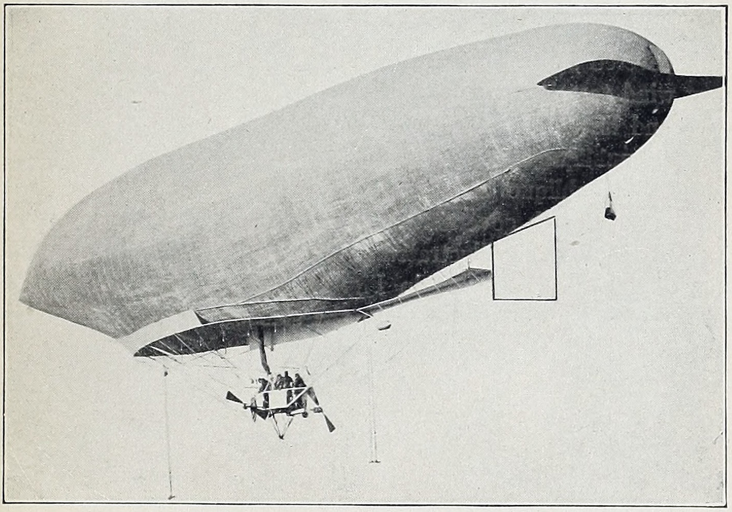
Fig. 9. La Patrie, French War Dirigible
The next year a new and larger balloon equipped with a more powerful motor was used. Many flights were made in tests for the French War Department.
La Patrie. La Patrie was then built for the French government by the Lebaudy Brothers and was of the same design as their earlier airships. In speed it was nearly equal to Zeppelin’s, and its dirigibility was nearly perfect. Fig. 9 shows a view of this airship in flight.
It was 200 feet long, and the 70-horsepower engine drove two propellers. It could carry seven people and one-half ton of ballast. It carried four people at a speed of 30 miles per hour. On its last trip it covered 175 miles in seven hours. A few days afterward, a heavy wind tore it away from its moorings and it was blown out to sea and lost.
La Republique and Le Jaune. Two more airships of the same type, La Republique and Le Jaune, followed this. These were tried by the French government, in 1908, and both proved successful. La Republique is illustrated in Fig. 10. The shape and equipment of the car are shown in Fig. 11. The automobile type of radiator may be seen attached to the side of the car. During a flight in the fall of 1909, a propeller blade broke and was thrown clear through the balloon envelope, causing the balloon to fall from a height of 500 feet. The four officers who formed the crew of the dirigible were killed instantly.
Clement-Bayard II. The numerous factors that must be considered in the design of a successful dirigible balloon as well as the many conflicting conditions that must be reconciled have already been referred to in detail. How these are carried out in practice may best be made clear by a description of what may be considered as an advanced type of dirigible, the Clement-Bayard II, Fig. 12, of French design, and the most successful of the French military air fleet. Its predecessor, the Clement-Bayard I, Fig. 13, made thirty voyages, some of them of considerable distances, without suffering any damage, but a study of its shortcomings led to their elimination in the following model.
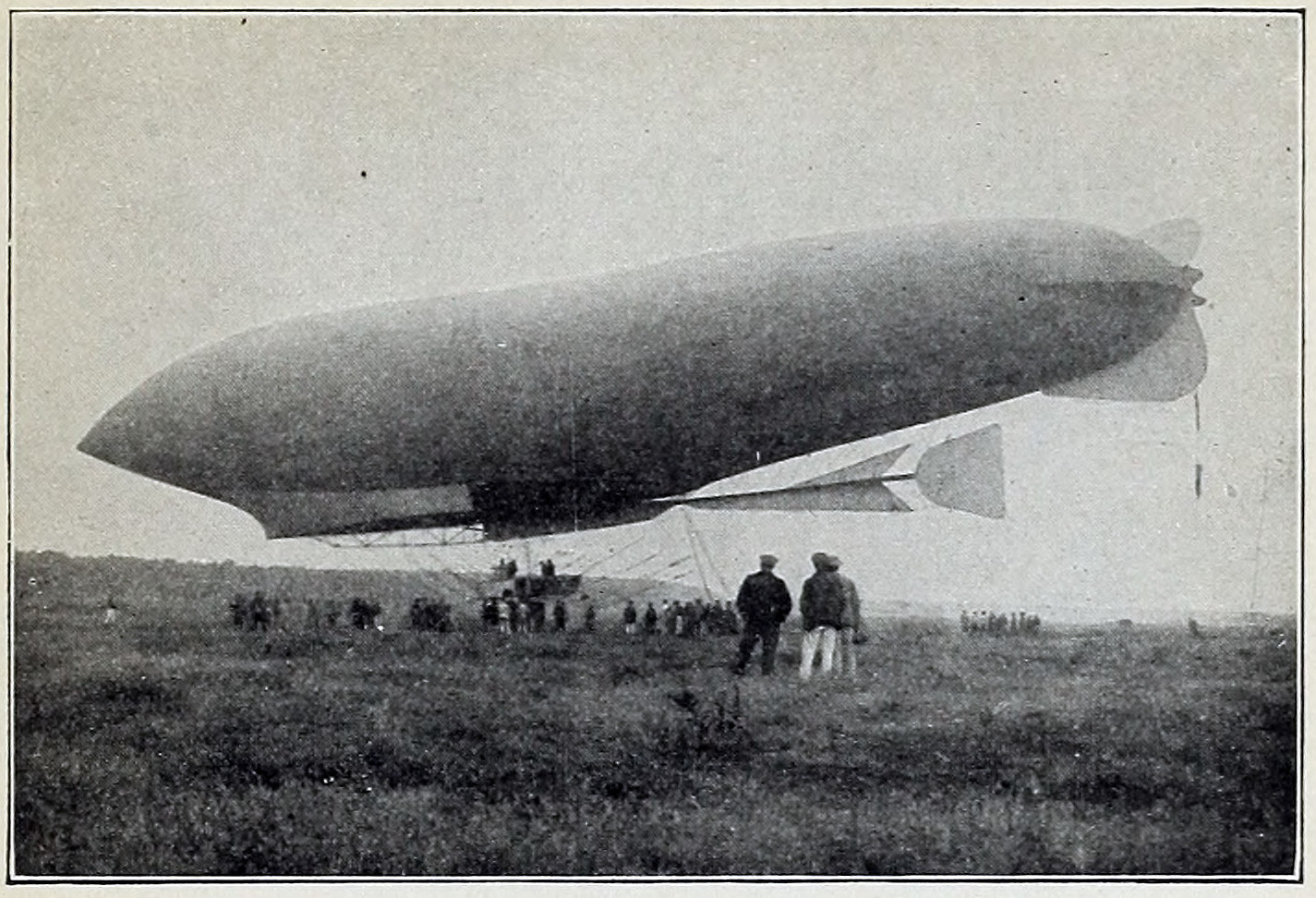
Fig. 10. La Republique, French War Dirigible
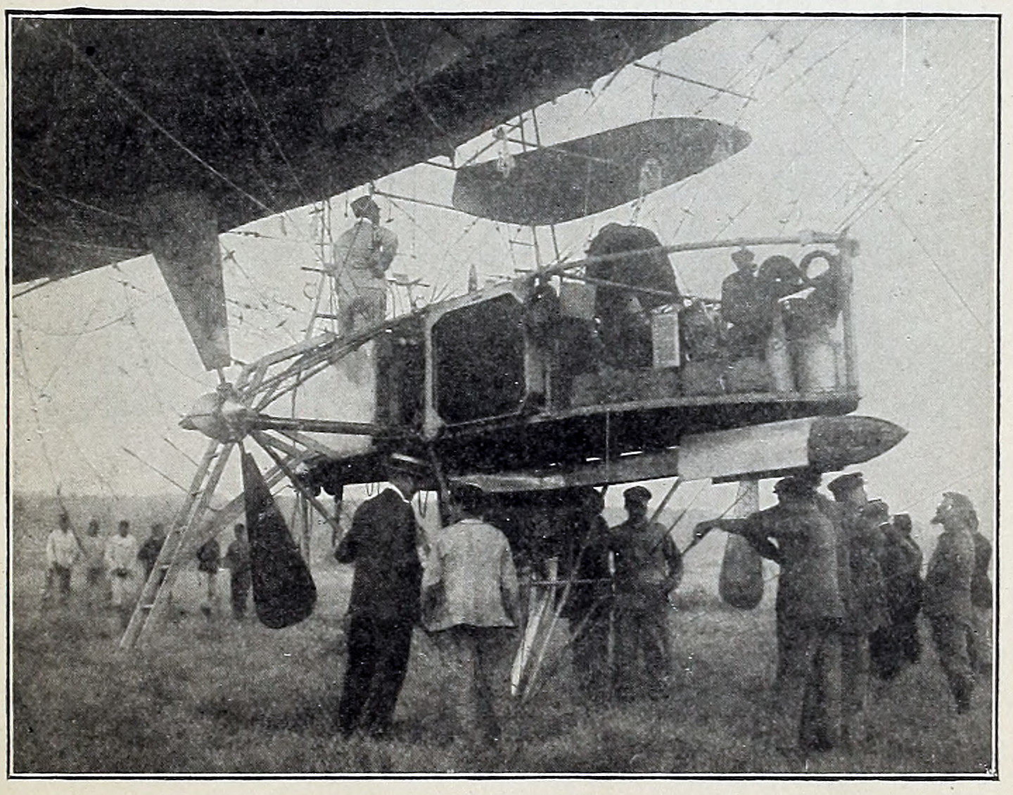
Fig. 11. Car of La Republique
The pisciform shape of the first Clement-Bayard was retained but given more taper, the dimensions being 248.6 feet overall by 42.9 greatest diameter, this being but a short distance back of the bow. This gives it a ratio of length to diameter of 5.76. The gas balloonet stabilizers were eliminated altogether, Fig. 12. The total gas capacity is approximately 80,000 cubic feet. Like all French dirigibles it is of the true flexible type, the only rigid construction being that of the framework of the car itself. To the latter are attached all rudders and stabilizing devices, instead of making them a part of the envelope as formerly. The latter is made of continental rubber cloth.
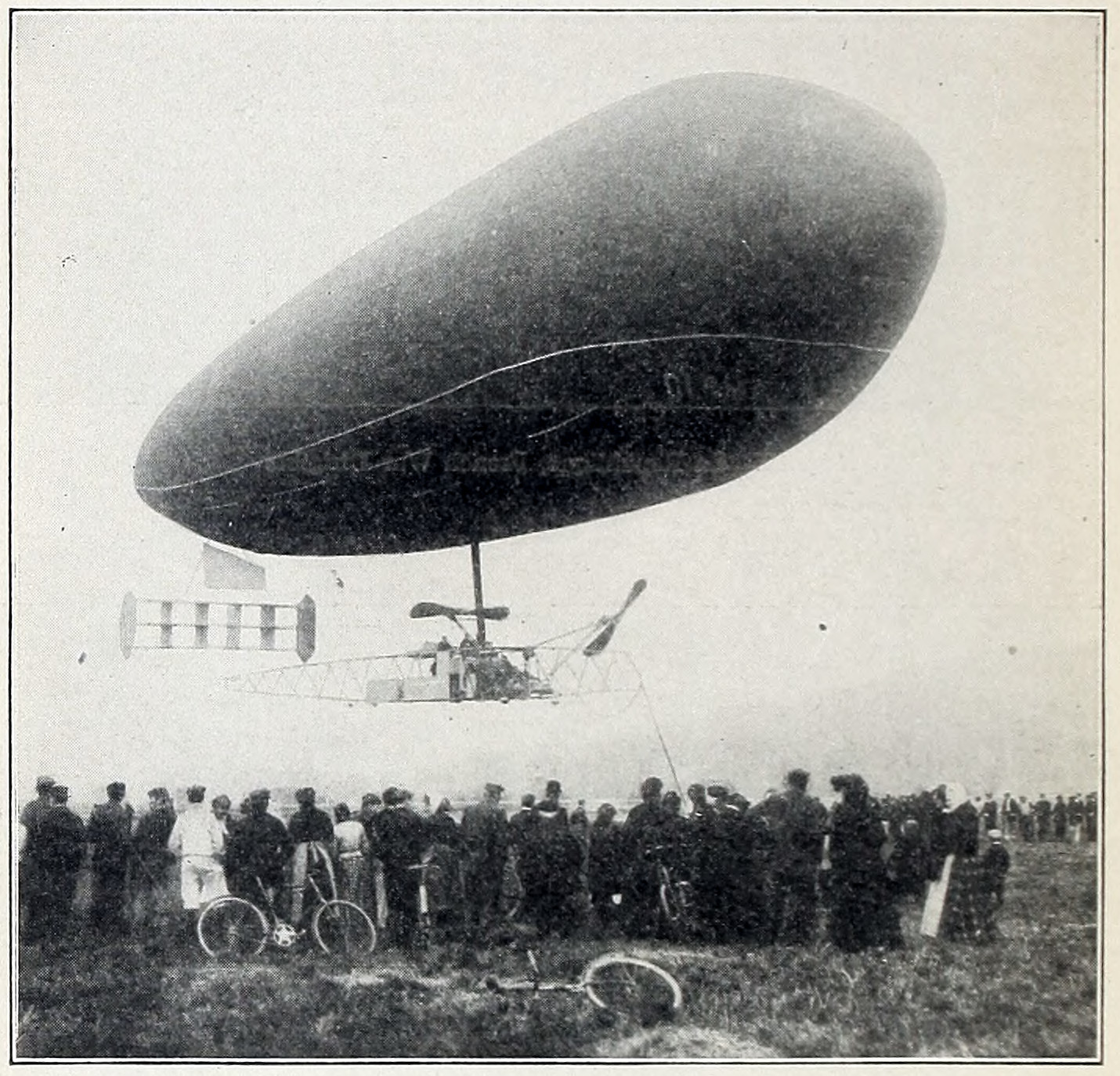
Fig. 12. Clement-Bayard II, French Dirigible
Light steel and aluminum tubing are employed in the construction of the frame supplemented by numerous piano-wire stays. This frame extends almost the entire length of the envelope and carries at its rear end a cellular, or box-kite, type of stabilizing rudder, instead of the former gas balloonets employed on the Clement-Bayard I, Fig. 13. This cellular rudder is in two parts, consisting of two units of four cells each, the two groups being joined at the top, with a space between them. In addition to acting as a stabilizer, this is also the direction rudder, its leverage being increased by making the end planes somewhat larger than the partitions of the cells. Between the cellular stabilizing rudder and the envelope is placed the horizontal rudder for ascending or descending. In the illustration this appears to be a flag, but it is in reality a long rectangular plane, which may be tilted on its longitudinal axis, the latter being at right angles to that of the balloon. There are two air balloonets of about one-third the total capacity of the balloon itself, and they are designed to be inflated by large aluminum centrifugal blowers driven from the main engines themselves.
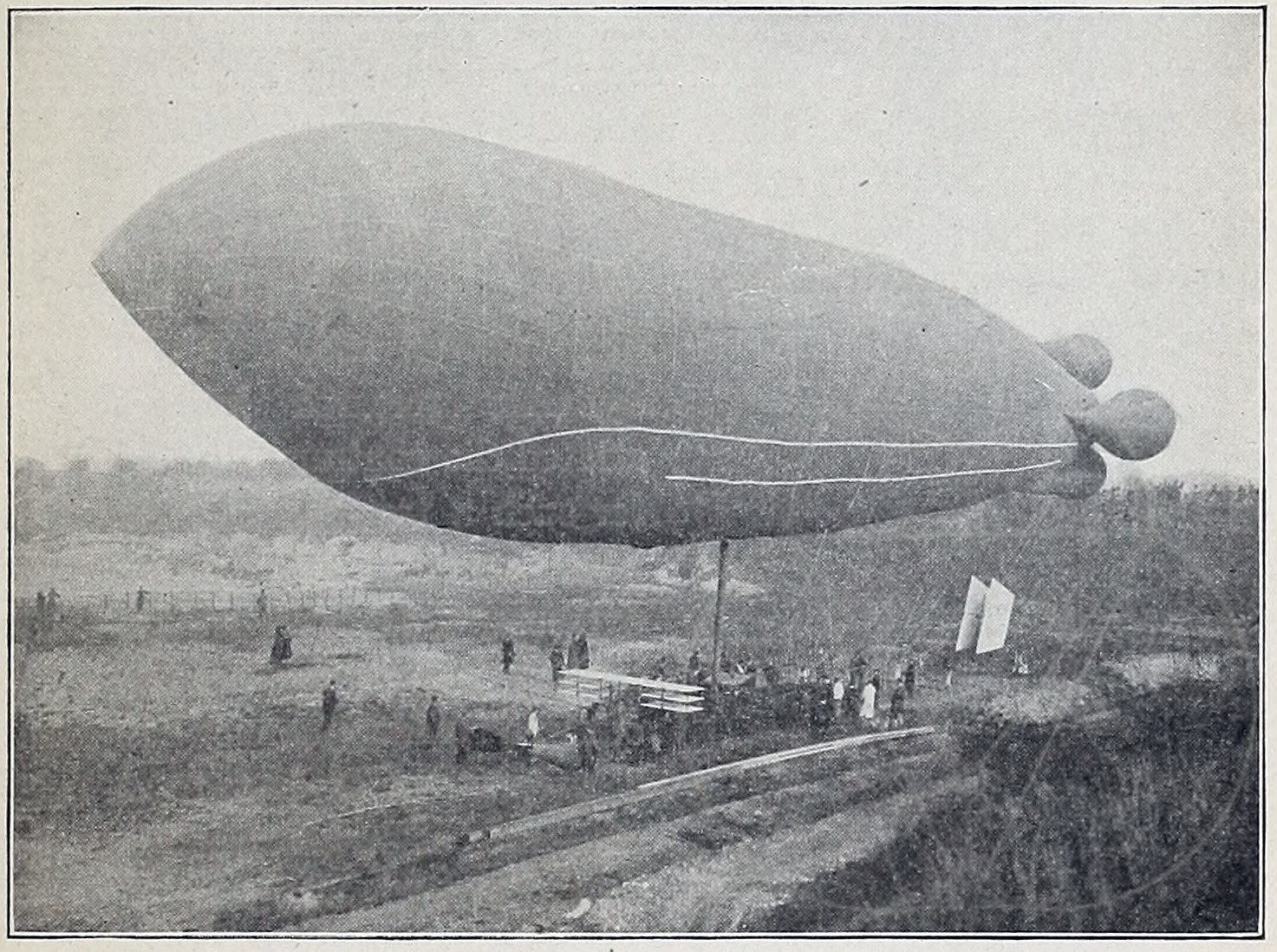
Fig. 13. Clement-Bayard I
There are two motors, each of 125 horsepower, both being of the same conventional design, i.e., four cylinder four cycle vertical water cooled. In fact, they are merely light automobile motors. The cylinders have separate copper water jackets and the motors themselves are muffled, which is a departure from the usual custom. Each drives a separate propeller carried on top of the main frame through bevel gearing.
The Clement-Bayard II made itself famous by its rapid and successful flight from the suburbs of Paris across the Channel to London, in October, 1910.
Astra-Torres. In reviewing the specifications of any of the big dirigibles, the observer cannot fail to be struck by the excessive amount of power necessary to drive them at speeds which are lower than the minimum, or landing speeds, of many aeroplanes. When a speed of 45 miles per hour was first reached by a dirigible, it was acclaimed as a great feat. But this comparatively moderate rate of travel was surpassed only by increasing the number of motors and their horsepower until the fuel consumption became exceedingly high. This necessitated the carrying of a great weight of fuel and cut down correspondingly the useful load that the dirigible was capable of lifting as well as restricted its radius of flight at full speed. Until aerodynamic research had demonstrated the contrary, the necessity for such a tremendous amount of power was considered necessary to overcome the head resistance of the balloon itself. Research brought out in a striking manner how great a proportion of the total head resistance of an aeroplane was due to the struts and bracing wires. In the construction of the different types of airships illustrated, it will be noted that the gear provided for suspending the car or cars below the balloon requires a great number of cables. Later developments showed that by eliminating the great amount of head resistance caused by these numerous surfaces, the speed of a dirigible could be increased by over 50 per cent with the same amount of power.
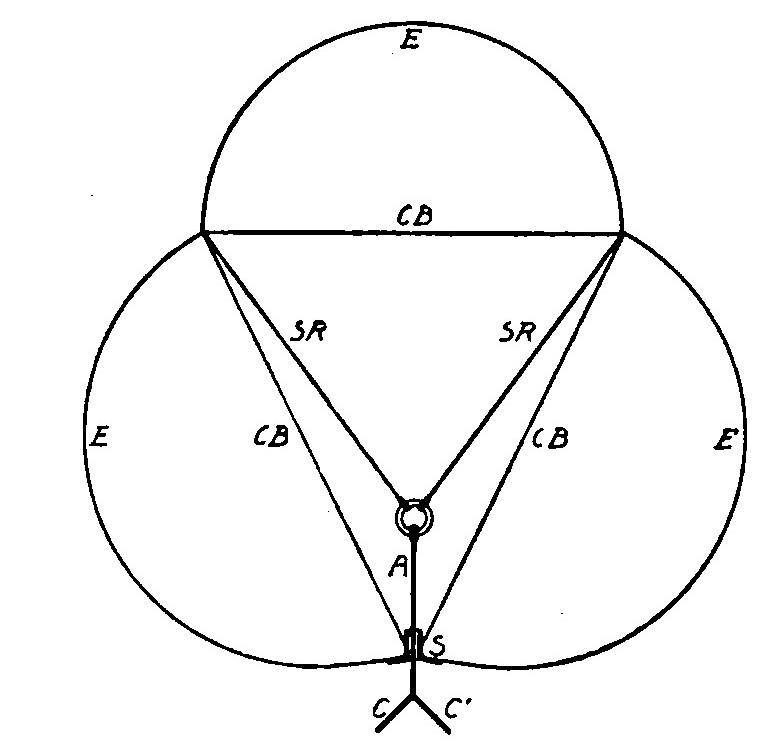
Fig. 14. Section of Astra-Torres, Illustrating Method of Suspension. CB, Bracing of Heavy Fabric Bands; SR and A, Suspension Ropes and Cable Passing through Envelope; S, Expansion Sleeve in Envelope; CC', Ropes to Sides of Car; E, Envelope
Improved Suspension. The shortcoming of the dirigible with reference to suspension was realized more than ten years previous by a Spaniard—Torres—but owing to lack of financial support, he was unable to put his idea into execution. The principle he evolved is made clear by Fig. 14, which gives a section of an Astra-Torres dirigible illustrating the method of suspension. Instead of the ropes SR used to suspend the car being attached to bands passing around the envelope, these reinforcing bands CB and also the ropes fastened to them are placed inside the envelope, thus eliminating head resistance from those sources.
Performance. Failing to obtain any encouragement in Spain, Torres finally succeeded in interesting the French Astra Company, which built a vedette, or scouting airship, of a little over 50,000 cubic feet capacity. It was pitted against the Colonel Renard, at that time the leading unit in the French aerial navy and the fastest airship in commission. The small Torres dirigible so completely outclassed its huge competitor that another of close to 300,000 cubic feet capacity was built and tried against the Parseval with similar results. An Astra-Torres dirigible built for the British government showed a speed in excess of 50 miles per hour. This particular dirigible has been at the front in France almost since the outbreak of hostilities and has rendered considerable valuable service. Its success led the French Government to order a huge replica of it, having a capacity of over 800,000 cubic feet and with motors developing 1,000 horsepower, which would give it an indicated speed of 60 miles per hour. So confident were its builders of attaining or even exceeding this, that an order for a second and even larger airship of the Astra-Torres design was placed before the first one was finished. This is also fitted with motors aggregating 1,000 horsepower and displaces 38 tons, making it larger than any Zeppelin that had been constructed up to the time it was built. As its construction and trials were undertaken during the war, no details have been published, but it is said on good authority that its speed exceeds 60 miles per hour, so that it is faster than any of the German dirigibles.
Construction. Unlike the German dirigibles, the larger types of which have been characterized by a rigid frame, the Astra-Torres is a flexible airship and, owing to its method of suspension, its external appearance is decidedly unconventional, since the envelope instead of being of the usual cigar shape is more like a triangular bundle of three cigars with the third one on top. At the point where the three envelopes join, as shown in section, Fig. 14, heavy cloth bands CB are stretched across the arcs, forming a chord across each arc, the three chords comprising an inverted triangle. The suspension ropes SR are attached to the opposite ends of the base of this inverted triangle and converge in straight lines downward through the gas space, so that the air resistance offered by the ropes is practically eliminated since only a very small part of the suspension system appears outside the envelope. This external part consists of vertical cables A attached to the collecting rings of the bracing system and extending downward through special accordion sleeves S which permit the free play necessary at the points where they pass through the outer wall of the envelope. These sleeves also have another function—that of permitting the escape of gas under the pressure of expansion. A short distance below the envelope E each of these cables splits into two parts C and C' attached to opposite sides of the car.
The British airship mentioned is provided with but one car, but the larger French ships have two placed tandem, each of which carries a 500-horsepower motor driving two two-bladed propellers of large diameter. While the form of envelope made necessary by this construction increases the frictional resistance, this is negligible in comparison with the great saving in power effected by the method of suspension, not to mention the greater simplicity of construction.
GERMAN DIRIGIBLES
Early Zeppelin Airships. At the same time that Santos-Dumont was carrying on his hazardous experiments, the problem was being attacked along slightly different lines by Count Zeppelin.
It will be remembered that Dumont experienced much trouble on account of the envelope of his balloon being too flexible, causing it to crumple in the middle and to become distorted in shape from the pressure of the air. His efforts to overcome this by the employment of air bags did not meet with great success, even in his later types.
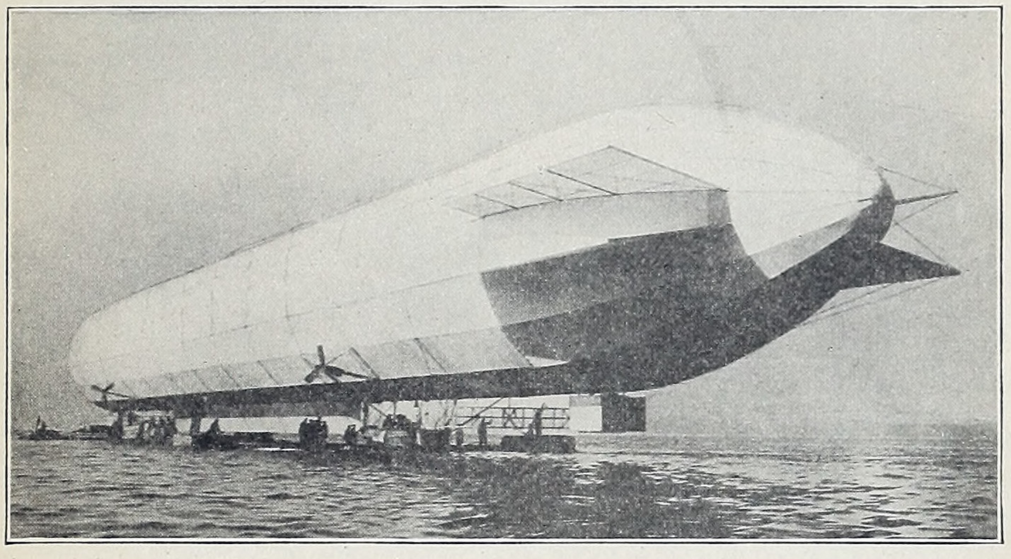
Fig. 15. Zeppelin Dirigible Rising from Lake Constance
Construction. Zeppelin employed a very rigid construction. His first balloon, which was built in 1898, was the largest which had ever been made. It is illustrated in Fig. 15, which shows his first design slightly improved. It was about 40 feet in diameter and 420 feet long—an air craft as large as many an ocean vessel. The envelope consisted of two distinct bags, an outer and an inner one, with an air space between. The air space between the inner and outer envelopes acted as a heat insulator and prevented the gas within from being affected by rapid changes of temperature. The inner bag contained the gas, and the outer one served as a protective covering. In the construction of this outer bag lies the novelty of Zeppelin’s design. A rigid framework of strongly braced aluminum rings was provided and this was covered with linen and silk which had been specially treated to prevent leakage of gas. The inner envelope consisted of seventeen gas-tight compartments which could be filled or emptied separately. In the event of the puncture of one of them, the balloon would remain afloat. An aluminum keel was provided to further increase the rigidity. A sliding weight could be moved backward or forward along the keel and cause the nose of the airship to point upward or downward as desired. This would make the craft move upward or downward without throwing out ballast or losing gas. Lender each end of the balloon a light aluminum car was rigidly fastened and in each was a 16-horsepower Daimler gasoline engine. The two engines could be worked either independently of each other or together. Each engine drove a vertical and horizontal propeller. The propellers each had four aluminum blades. As will be seen from Fig. 15, the ears were too far apart for ordinary means of communication and so speaking tubes, electric bells, and an electric telegraph system were installed.
First Trials. Very little was known as to the effects of alighting on the ground with such a rigid affair as this vessel, therefore the cars were made like boats so that the airship could alight and float on the water. The first trials were made over Lake Constance in July, 1900. The mammoth craft was housed in a huge floating shed, and the vessel emerged from it with the gas bag floating above and the two cars touching the water. She rose easily from the water, and then began a series of mishaps such as usually fall to the lot of experimenters. The upper cross stay proved too weak for the long body of the balloon and bent upward about 10 inches during the flight. This prevented the propeller shafts from working properly. Then the winch which worked the sliding weight was broken and, finally, the steering ropes to the rudders became entangled. In spite of all this, a speed of 13 feet per second, or about 9 miles per hour, was obtained. These breakages made it necessary to descend to the lake for repairs and in alighting the framework was further damaged by running into a pile in the lake. The airship was repaired and another flight was made later in the year, during which a speed of 30 feet per second, or 20 miles per hour, was obtained.
Second Airship. Zeppelin had sunk his own private fortune and that of his supporters in his first venture, and it was not till five years later that he succeeded in raising enough money to construct a second airship. No radical changes in construction were made in the new model, but there were slight improvements made in all its details. The balloon was about 8 feet shorter than the original and the propellers were enlarged. Three vertical rudders were placed in front and three behind the balloon, and below the end of the craft horizontal rudders were installed to assist in steering upward or downward. The steering was taken care of from the front car.
The most important change was made possible by the improvement in gasoline engines during the preceding five years. Where, in the earlier model, he had two 16-horsepower engines, he now used an 85-horsepower engine in each car, with practically the same weight. In fact, the total weight of the vessel was only 9 tons, while his first airship weighed 10 tons.
His new craft made many successful flights. One was made at the rate of 38 miles per hour and continued for seven hours, covering a total distance of 266 miles.
Later Zeppelins. The later Zeppelins embody no remarkable changes in design, the principal alteration being in size. One of these is illustrated in Fig. 16. In this the gas bag was increased to 446 feet in length and it held over 460,000 cubic feet of gas. This gave it a total lifting power of 16 tons. With this, Zeppelin made a voyage of over 375 miles. He was in the air for twenty hours on this trip and carried eleven passengers with him.
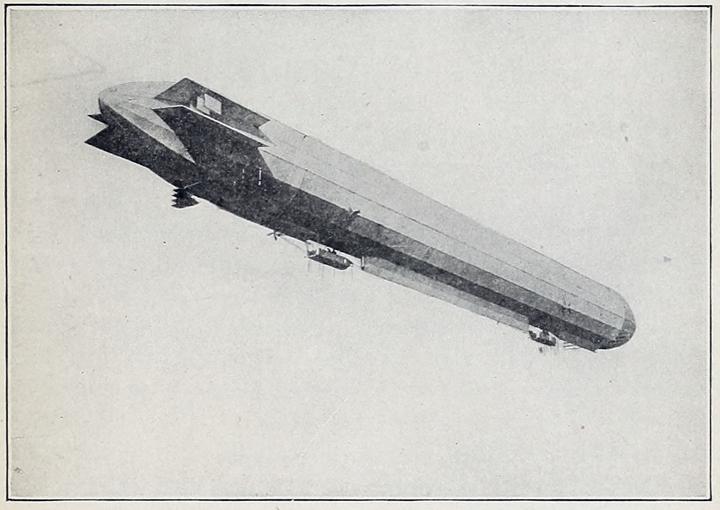
Fig. 16. Zeppelin Airship in Flight
In August, 1908, the Zeppelin left its great iron house at Friedrichshafen and sailed in a great circle over Lake Constance. The day after it started, however, it was destroyed by a storm, and sudden destruction from one cause or another has ended the existence of practically every one of the Zeppelins built since, usually after a very brief period of service.
Shape and Framing. In the early days of dirigible design the data upon which the shape and proportions of the envelope were based were purely empirical. Schwartz, Germany’s pioneer in this field, adopted the projectile as representing the form offering the least air resistance and accordingly designed his envelope with a sharply pointed bow and a rounded-off stern, giving it a length four times its diameter. Zeppelin did not agree with these conclusions and adopted a pencil form, rounded at the nose and tapering to a sharp point at the stern, making the length nine to ten times the diameter. Subsequent research work in the aerodynamic laboratory has demonstrated that the most efficient form for air penetration is one having a length six times its maximum diameter with the latter situated at a point four-tenths of the total length from the bow. It has likewise been proved that an ellipse is more efficient than either the projectile or pencil form and that tapering to a sharp point at the stern offers no particular advantage. As a result, the most approved form resembles the shape of a perfecto cigar, the nose being somewhat blunter than the after end. This form is likewise that of the swiftest-swimming fishes and has been shown to have the least head resistance as well as the minimum skin friction; it results in a section to which the term stream-line has been applied, and it is now employed on all exposed non-supporting surfaces on aeroplanes, such as the struts and even the bracing cables. Laboratory research has demonstrated that it is worth while to reduce the head resistance of even such apparently negligible surfaces as those presented by these wires and cables and, therefore, they are stream-lined by attaching recessed triangular strips of wood to their forward sides.
Framing Details. Despite this, the builders of the Zeppelins have adhered to the original pencil shape with but slight modifications at the bow and stern, probably because that shape is much easier to build and assemble from standard girders. The form of girder employed is shown in Fig. 17, while the complete assembly of the frame is illustrated in Fig. 18. The girders form the longerons, or longitudinal beams, running the entire length of the rigid frame and supported at equidistant points by ring members built of similar girder sections. The fourth ring from the nose and each alternate ring after that are further braced by being trussed to the longitudinal beams around their entire circumferences, as shown in Fig. 18. The larger V-shaped truss at the bottom forms the gangway, which is now placed inside the envelope instead of being suspended beneath it, as formerly. This is done to eliminate the head resistance set up by the additional surface thus exposed. In the first instance in which this gangway was incorporated in the envelope, no provision was made for ventilation, and the ship was wrecked by a gas explosion. Regardless of how tight the fabric is made, gas is always oozing out through it to a greater or less extent. This fact is now met by providing ventilating shafts leading from the gangway to the upper surface of the envelope. Additional shafts through the envelope lead to gun platforms, forward, amidships, and aft, and are reached by aluminum ladders.
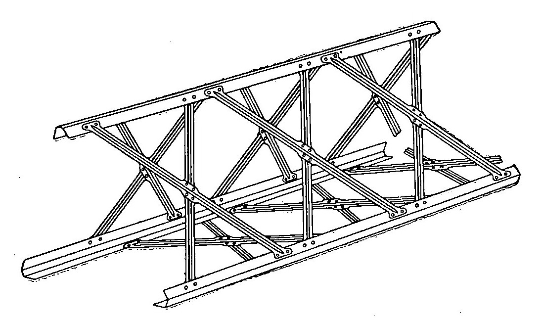
Fig. 17. Trellis Type of Aluminum Girder used in Longitudinals of Zeppelin Frame
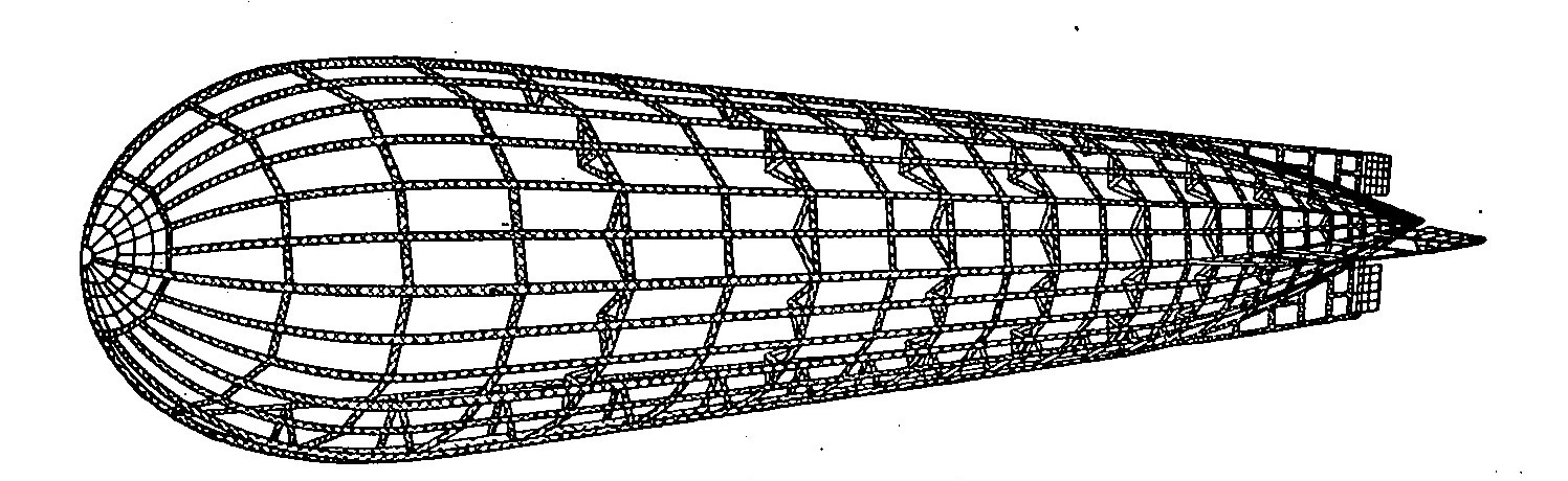
Fig. 18. Aluminum Frame Construction of Zeppelin Hull
Framing of Schutte-Lanz Type. It has become customary to refer to all large German airships as Zeppelins, but many of those used during the past three years have been of the Schutte-Lanz build, which is also a rigid frame type of dirigible but has been designed with a view of overcoming some of the disadvantages of the aluminum frame construction encountered in the use of the Zeppelin. The length and diameter of the latter airships are such that, no matter how rigidly the framing is assembled, there is more or less sag. When the sag exceeds a certain amount, the frame is apt to buckle at the point where it occurs, involving expensive repairs or wrecking the airship altogether. To overcome this difficulty, the Schutte-Lanz type employs a rigid frame of flexible material, namely, laminated wood in strip form, held together at joints and crossings by aluminum fittings and braced inside by cables. As shown by Fig. 19, no rigid longitudinal beams are employed, the only girders used being rings, to which a network built of the wood strips is attached. Starting at the nose, each continuous strip follows an open spiral path such as would be traced in the air by a screw of very large pitch, in fact, approximating the rifling of a gun barrel. It will also be noted from the illustration that the form of the Schutte-Lanz airship is the cigar-shape, which laboratory research has shown to be the most efficient.
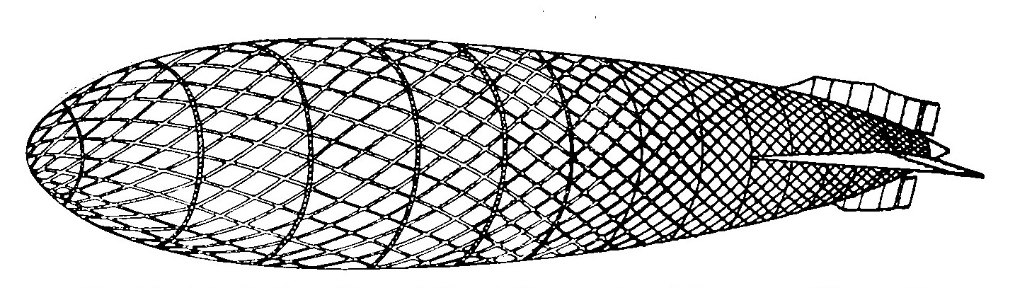
Fig. 19. Schutte-Lanz Type of Frame Construction of Laminated Wood with Aluminum Fittings
The use of wood in conjunction with the spiral construction of the supporting members of the framing affords the maximum degree of flexibility, since the displacement of any of these members under stresses of either tension or compression would have to be very great to cause damage to the frame as a whole. The frame not being rigid, strictly speaking, either as units or as a complete assembly, stress at any particular point would simply cause all the members near that point to give in the direction of the strain, and the rest of the frame would accommodate itself to their change of position by either elongating or shortening slightly. In addition to these advantages, the Schutte-Lanz type of construction is said to be lighter than the Zeppelin for an airship of the same load-carrying capacity.
Power Plant. Compared with their successors of war times, the early Zeppelins were mere pigmies where power is concerned. Many of these pioneers were driven by less than 100 horsepower all told, whereas in the later types no single motor unit as small as this total has been employed. The motors used most largely have been the 160-horsepower Mercedes and the 200-horsepower Maybach, both of which are described in detail under the title "Aviation Motors." From five to ten of these units have been used on a single ship, giving an aggregate in some of the latest types of close to 2,000 horsepower. Power has been applied through five or six propellers to limit their diameter and to guard against the breakdown of any one of the units putting the power plant out of commission as a whole. To distribute the weight of the engines equally and to insure each propeller a position in which it can work in undisturbed air, the engines have been placed at widely separated points on the airship and in different planes so that no two are coaxial. The main engine room is usually located in a cabin just back of the operating bridge and wireless room, while the remaining motors are suspended in independent gondolas at different points along the sides. Where more than 1,000 horsepower has been used, each of these gondolas' has been fitted with two motors placed side by side and so coupled that either one or both may be employed to drive the single propeller carried by the propelling car. All the more recent propellers have been of the two-bladed type.
Control Surfaces. The numerous expedients formerly resorted to by various designers in providing for stabilizing, steering, and elevating surfaces have been abandoned for forms that are practically a duplication of aeroplane practice. Experience demonstrated that the different types of multiplane rudders, elevators, and stabilizing surfaces employed in earlier days not only offered no operating advantages but were actually detrimental, in that they increased the head resistance unnecessarily. Moreover, their complication meant increased weight and weaker construction. They have accordingly been displaced by monoplane surfaces which are of exactly the same type of construction as those used on the aeroplane and the location and proportions of which are very evidently based on aeroplane practice. Both the horizontal and vertical stabilizers are of approximately triangular form and have the steering and elevating surfaces hinged to them at their after ends, so that, except for the pointed extremity of the envelope which extends beyond them, the tail unit of the later Zeppelins is practically the same as the empennage of an aeroplane. The horizontal surfaces are apparently depended on entirely to effect the ascent and descent, there being no evidence of swiveling propellers by means of which the power of the engines could be employed to draw the airship up or down. The great weight of ballast carried is, of course, in the form of water, but this is discarded in order to ascend only when the power of the engines exerted against the elevating planes is no longer capable of keeping the airship at the altitude desired. In the low temperatures encountered in night flights, however, the contraction of the hydrogen gas is so great that the crew has found it necessary to reduce the weight by discarding not only every pound of ballast but, as far as possible, everything portable. Despite this, several airships have fallen when their fuel supply was exhausted, one coming to the ground in Scotland, two dropping into the North Sea, and three or four falling in France.
Operating Controls. All the operating controls are centered at the navigating bridge, which is inclosed to form the commander’s cabin. By means of push buttons, switches, levers, and wheels every operating function required is set into motion from this central point. Whether auxiliary motors are carried for the purpose of pumping air into the balloonets or this is one of the duties of the main engine just back of the wireless room does not appear, but with the aid of a push button board the amount of air in any of the balloonets may be increased or decreased at will. There is a control button for each operation, or two for each balloonet, which fact necessitates a rather forbidding looking board, since the more recent Zeppelins have seventeen to nineteen gas bags within each of which is incorporated an air balloonet.
The amount of fuel supplied to any one of the motor units can likewise be controlled from a central board, and this is also true of the ballast release apparatus, so that water can be emptied from any one of the ballast tanks at will, thus facilitating ascent or descent by lightening one end or the other. Elevating and steering surfaces are operated by small hand-steering wheels with cables passing around their drums, a member of the crew being stationed at each of these controlling wheels. Owing to the number of motors used, the instrument board is the most formidable appearing piece of apparatus on the bridge, since there is a revolution counter for each power unit in addition to the numerous other instruments required. Some of these instruments are the aneroid barometer for indicating the altitude, transverse and longitudinal clinometers to show the amount of heel and the angle at which the airship is traveling with relation to the horizontal, the anemometer, or air-speed indicator, manometers, or pressure gauges, for each one of the gas bags, fuel and ballast supply gauges, drift indicators, electric bomb releasers, mileage recorders, and the like. In addition to these, there are a large chart and a compass, so the navigating bridge of a Zeppelin combines in small space all the instruments to be found in the engine room and on the bridge of an ocean liner besides several which the latter does not require. That the proper coordination of all the functions mentioned is an exceedingly difficult task for one man seems evident from the numerous Zeppelins that have apparently wrecked themselves.
Crew Carried. In the various Zeppelins that have been captured or shot down by the British or French, the personnel has varied from fifteen to thirty men but in the majority of instances has not exceeded twenty. The positions and duties are about as follows: The commander, lieutenant-commander, and chief engineer, and possibly a navigating officer are stationed at the bridge. Two or three of the crew are also stationed there to work the manually operated controls. In the cabin just back of the bridge are two wireless operators and one or two engine attendants for the motors in the engine room behind the wireless room. A similar number of engine attendants are stationed in the after engine room and there is at least one attendant for each of the other motor units. One man is stationed at each machine gun, of which there are three to five on the "roof" and two in each car, and at least as many bombers are needed to load the "droppers." As a reserve there are usually an additional gun pointer for each gun and an extra engine attendant, since to run continuously most of the crew would have to stand watch and watch as in marine practice. The sleeping accommodations consist of canvas hammocks slung in the gangway.
Explosives Carried. In addition to a liberal supply of ammunition for the machine guns, a large weight of bombs is carried, though the quantity as well as the size of the bombs themselves has been exaggerated in the same or even greater ratio than that which has proved characteristic of the German military press-agency service. The bombs are carried suspended in racks amidships, and the bomb droppers are also located at that part of the ship so that the release of the bombs will not upset the longitudinal equilibrium of the craft. The bomb-dropping apparatus is controlled electrically from the navigating bridge but may also be operated by hand from the same point. It has been reported by the Germans that their latest types of Zeppelins are capable of dropping bombs weighing 1 ton each. In view of the effect that the sudden release of a weight of 1 ton would have on the airship itself, this is manifestly very much of an exaggeration. Zeppelin bombs that have failed to explode have never exceeded 200 to 300 pounds and many of those employed are doubtless still lighter. So far as the total amount carried is concerned, many of the later airships doubtless are capable of transporting 2 to 3 tons and still carrying sufficient fuel, though adverse conditions would prevent their return, as has frequently happened.
BRITISH WAR DIRIGIBLES
Adoption of Small Type. German designers have continued to pin their faith blindly to the huge rigid type, despite the fact that prior to the war almost a dozen of these costly machines met with disaster as fast as they could be turned out. Since the war started, their destruction has kept pace pretty closely with their building without their accomplishing anything of military value. The British naval aeronautic service, on the other hand, appreciated the futility of such tremendous and unwieldy construction and, after a single demonstration of its uselessness, abandoned it altogether. This single attempt was the ill-fated Mayfly, which was most appropriately named, since its performance resolved into a certainty the doubt expressed by its title. In being taken out of its shed, the framing of the airship was damaged, and it collapsed a few minutes later so that it never did fly. One of the early types of small British dirigibles is shown in Fig. 20.
Attention has since been concentrated in most part on the construction of aeroplanes in constantly increasing numbers, although the dirigible has not been given up altogether. However, its restricted usefulness as well as the necessary limitations of its effective size has been recognized. Early in the war Great Britain planned the construction of fifty small dirigibles, of both the rigid and nonrigid types, all of which have undoubtedly since been completed. They are small airships designed chiefly for scouting and short-range bombing raids over camps when in army service and for coast patrol and submarine hunting as an aid to the naval forces. While no specifications are available, the cubic capacity of these patrol airships probably does not exceed 50,000 to 75,000 cubic feet, their over-all length being approximately 100 to 125 feet.
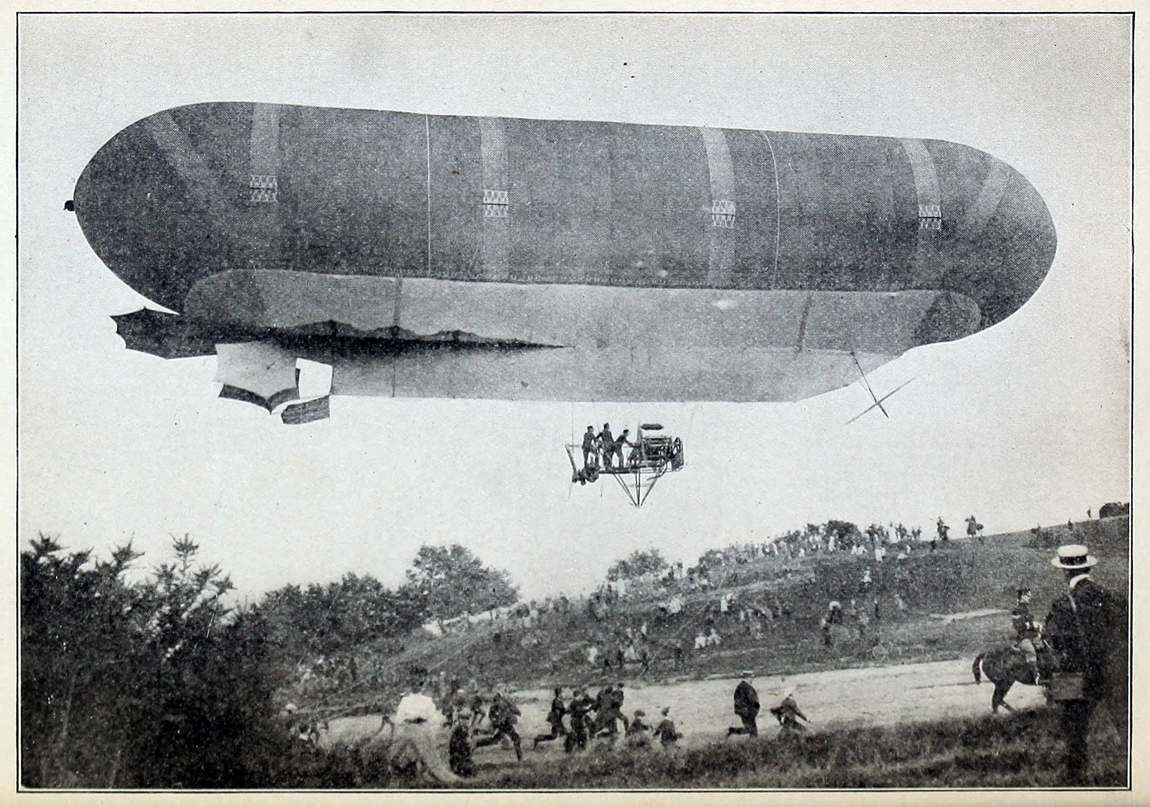
Fig. 20. An Early Type of Small British Dirigible
Aeroplane Features. To simplify the construction and at the same time minimize the amount of head resistance, the car consists of an aeroplane fuselage of the tractor type, fitted with a comparatively small motor—under 100 horsepower—and having accommodations for a pilot and an observer in two cockpits, placed tandem. The control surfaces are also similar to those used in aeroplane construction. Despite their low power, these dirigibles can make 40 miles an hour, owing to their greatly reduced head resistance. Instead of employing either an auxiliary blowing motor or a blower driven by the motor itself, the supply duct to the air balloonet is made rigid and is sloped forward so that its open end comes directly in the slip stream of the propeller; thus the latter serves to inflate the balloonet as well as to drive the dirigible. The desired amount of inflation is controlled by a valve.
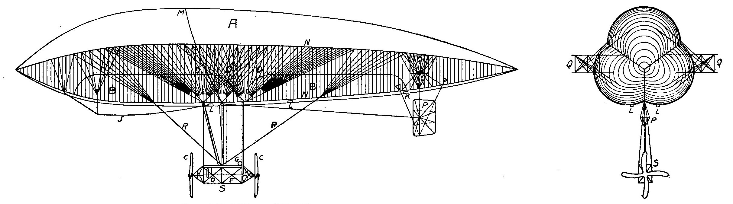
Fig. 21. Side and End Views of British Astra-Torres Dirigible Used for Anti-Submarine Patrol Service
Use in Locating Submarines. Many of these small scouting and naval-patrol dirigibles have given a good account of themselves and comparatively few have met with accident or have been destroyed by the enemy. On frequent occasions they have been very successful in locating submarines below the surface, since the body of the under-water boat is readily detected from an altitude of a thousand feet or more, even though submerged to a great depth and despite a heavy ripple on the surface that makes the water absolutely opaque when viewed from the deck of a ship. Doubtless they will be employed to an increasing extent as the hunt for the submarine becomes more and more intensive, though their use is very much restricted during the winter months, owing to the frequent and severe storms encountered.
British Astra-Torres. A number of comparatively small Astra-Torres dirigibles have also been built in Great Britain for coast patrol and anti-submarine work. The line drawing at the left of Fig. 21 illustrates the general design and construction of these small airships, while the various letters indicate the different parts of the gas container, air balloonets, suspension and car, and the end view at the right of the figure shows the small amount of head resistance offered by the suspension of this type as compared with that of the usual form of nonrigid dirigible. A is the balloon itself, or main gas container, the pressure relief valve for which is located at M. BB are the air balloonets connected with the blower H in the car. In the illustration these balloonets are shown fully inflated as they would be after the gas bag had lost a considerable proportion of its original contents through leakage or expansion. At the beginning of a flight, when the gas bag is fully inflated with hydrogen, they lie perfectly flat along the lower side of the envelope, being brought into service only as they are needed to keep the envelope distended to its full volume.
The novel method of suspension to which this type of dirigible owes its greater speed and fuel economy, because of the reduction of the head resistance, is shown by the numerous supporting ropes O-O-O, which terminate in a comparatively few cables attached to the car. In the small British airships referred to here, there is but one small car designed to carry a crew of two men and the engine is of comparatively low power, driving a propeller at either end of the car, but in the large French dirigibles of the same type, two large cars are placed tandem some distance apart and are fitted with 500-horsepower motors. The various parts indicated by the letters are: CC propellers, D motor, F space for pilot and crew, G fuel and oil tanks, J guide rope, K gas valve, LL air valves, NN balloonet cable, P rudder, Q stabilizer, RR bracing cables, and S the car itself.
MILITARY USES OF ZEPPELINS
Limitations of Use. Nothing excites the Teutonic imagination so strongly as things military to which the characteristic German adjective kolossal can be enthusiastically applied. It was for this reason that, despite its uniform record of tragic disaster for years before the war, the Germans pinned their faith to the Zeppelin as a weapon that could not fail to strike terror to the hearts of the British and French and make them hasten "to sue for peace." However, apart from its reputed employment on the single occasion that the German grand fleet left the security of the Kiel Canal, it is not known to have been used in any purely military operation. The aeroplane has been developed to a point that, in spite of the ability of the Zeppelin to ascend rapidly when hard pressed, would make it suicidal for one of the huge gas bags to sally forth in daylight, unless attended by a large number of battle planes to prevent enemy flying machines from attacking it. No such use of the Zeppelin has been recorded thus far. Consequently, it has been used only in nocturnal bomb-dropping expeditions, chiefly directed against London and only undertaken when weather conditions made detection difficult. In order to carry these out, it has been necessary to establish stations in Belgium, since the fuel consumption of the Zeppelin is so great that, even with its tremendous fuel supply of 3 to 5 tons, a flight to London and return to points well within the German border is impracticable. The first raids of this character were carried out successfully, but subsequent attempts were marked by the loss of one or two airships on each occasion, so that the practice was abandoned as being too expensive for the results attained and aeroplanes were substituted.
Number Built. Taking it for granted that the numbering of the German airships has been consecutive, the total number built during the first three and one-half years of the war by the Germans would be between eighty and one hundred. All large German airships have come to be commonly termed Zeppelins, but a number of them were of the Schutte-Lanz type, almost equally large and also characterized by rigid construction, which, however, was of wood with aluminum fittings instead of being all metal, as it was found that the huge metal frame accumulated a static charge of high potential that was responsible for igniting the gas in one or two instances.