CLASS V. The Distribution with Secondary Batteries, or the Battery Transformer System.
Reading edition
Mr. Lane Fox was the first to put forward a complete system of electrical supply on this plan, Fig. 23.
Fig. 23.
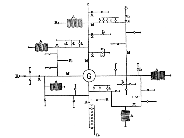
G Generating station. A Accumulators (secondary batteries).
R Returns. M Mains or conductors.
L Lamps. X Meters.
The system is discussed by him as follows:[4]—
“The chief points of the system is the use of a generator in a central position, from one pole of which insulated conductors or mains are led to the several points where the electric energy is to be utilised, being branched and sub-branched as much as required, and thence back to the other pole of the generator by an uninsulated conductor, such as the gas or water pipes. At certain points, storage or secondary batteries are set up in connection, on one hand, with the mains, sub-mains, and branches, as the exigencies of the case may require, and, on the other, with the return conductor.”
“The combination of generators, circuit and storage batteries is such, that when the current from the generators falls below the demands made on it from the various outlets to the mains at which its energy is utilised, the deficiency is made up from the storage batteries, which act in unison to supply the requisite quantity of energy. On the other hand, when the current from the generator exceeds in point of quantity the demands upon it at the various outlets, the excess goes to charge the storage batteries and to create a reserve to be called upon in case of need.”
The objection to the system which prevented it being put in practical operation was the use of the earth as a return conductor. Besides the great danger of short circuit, the gas and the water pipes, which are so thickly laid in most cities, would conduct the current and interrupt telegraphic and telephonic communication. The experiment of using storage batteries as reservoirs, from which a constant supply of electricity could be drawn as required, was tried on a considerable scale at Colchester, where a large installation was started in 1884, secondary batteries being placed in favourable positions, and charged by a high-tension current. The plan adopted is shown by Fig. 24.
Fig. 24.
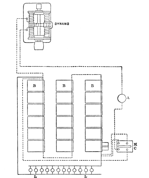
A is a meter in charging circuit; B, the batteries or accumulators; L, lamps in parallel on low-pressure service main.
The dynamos were two of the Brush type, each dynamo giving a current of 9·5 ampères, with an electro-motive force of 1,800 volts, when rotated at a speed of 700 revolutions per minute. They were driven by a semi-portable engine indicating 90 horse-power. The dynamos were coupled in parallel circuit for quantity, and excited by a small machine giving 10 ampères. The current was led some distance by a seven-strand 19 B. W. G. cable to the batteries, which were charged in series, the 60-volt lamps being placed in parallel on separate mains connected to the batteries. The danger of introducing a high-tension current of 1,800 volts into the houses was obviated by a rocking-switch worked automatically, so as to throw the batteries out of the charging circuit. The operation was accomplished by means of a master cell M, C, Fig. 24, similar to the others, but fitted with an arrangement to collect the gas evolved, which extended a diaphragm attached to a make-and-break arrangement which worked the rocking-switch. The Colchester installation did not turn out commercially successful, and has been abandoned; but the experiment has been valuable, and there is little doubt that, with simplification of details, a high-tension charging current could be led from a dynamo fixed in any convenient site where power is available; also in very crowded districts the batteries could be placed in cellars and be drawn from as reservoirs, so as to furnish a constant supply of electricity.
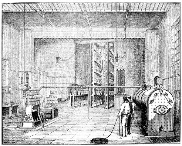
Fig. 25.
The Kensington Court installation has been previously quoted as an example of what promises to be one of the most successful methods of distributing a constant supply of electricity through a large area, a description of the station may therefore be interesting. The accompanying elevation, Fig. 25,[5] shows the unpretending design of the building, and the very compact arrangement of the generating machinery and batteries. When the illustration was made the plant consisted of one Willan’s single-crank triple-expansion engine in combination with a Crompton dynamo provided with vertical inverted single magnets, the output being 250 ampères at 140 volts when running at 500 revolutions per minute, the steam pressure being 160 lbs. on the square inch. A complete duplicate plant has already been installed, and three more sets of engines and dynamos are shortly to be erected. The draught from the boiler is led downwards by an underground flue, with the object of economising the very limited space as much as possible. As a rule, the dynamo and accumulators are used in parallel, the current enters and leaves the regulating cells by the same contact, in other words, there is only one switch which serves for charging and discharging the batteries. This switch has nine contacts, so as to give nine degrees of regulation of the light; when the dynamo and accumulators are working together, the lights are parallel with either 41, 42, or 43 cells, according to the amount of charge in the cells and current required, while, when the dynamo is out of circuit, the lights are worked off, 50, 51, 52, or 53 cells. The current passes through the usual measuring instruments, and each main conductor is protected by safety fuses mounted in a Hedges duplex cut-out. The accumulators are of the Planté type, but instead of being plain lead are sawn out of ingots which are cast porous on the Howell process. Each cell contains 35 plates, 8 in. × 8 in., and, as each plate when fully formed is said to be capable of yielding five ampère-hours per pound of lead, the cell has about 600 ampère-hours total capacity. In the event of a serious breakdown the whole of the work would fall on the accumulators, which could furnish a steady current for perhaps an hour or more; and herein lies the novelty of the arrangement. For the first time we have an accumulator put in not only as a fly-wheel to the whole system and to give the advantage of supplying current throughout the day and the small hours when the engine is not running, but also to act as an actual reserve. The routine is as follows:—the dynamo will start charging the accumulators a few hours before dusk; for a short time after lighting hours commence, the dynamo alone will supply sufficient current, but later on the demand will gain on the dynamo, and a certain portion of the discharge will be from the accumulators. At eleven o’clock at night the engine will be stopped and the accumulators will alone supply the demand for the rest of the night. In the small area occupied by the station there is ample room for a plant of six times the present capacity, and it is intended to erect sub-distributing stations at points at the outskirts of the district where accumulators to act as transformers will be fixed, which will be charged by a special main with a current of 500 volts, the outgoing wires from the sub-station taking electricity at the usual E.M.F pressure for incandescent lamps in houses of 100 volts.
Thirteen candle lamps are used in the district, having been found to be more convenient than 16 or 20 candle-power, the 13 candle is obtained for 36 watts, or 2·75 watts per candle. The price charged to consumers is 8d. per Board of Trade unit, or equivalent to gas at about 4s. 7d. the 1,000 cubic feet. Meters on the Aron plan, Fig. 17, are used, a card being supplied on which the readings are entered exactly similar to the method adopted with gas. The service mains terminate at the meter, where the company fix for their own purposes a double pole switch of the author’s design, Fig. 26, which enables both wires to be disconnected, a spring shut-off, marked S S, prevents the switch being left partly on.
System of Distribution.
The mains from the Kensington Court Station are laid underground in a culvert 18 in. by 12 in., which is built with brickwork and cement under the pavement. A double conductor of flat copper, 0·25 square inches section, is stretched from shackle insulators attached to iron bars, which are firmly built into the culvert; the continuity of the circuit is provided by means of stranded wire, which connects each section; the flat copper rests on the top of porcelain insulators, fixed on vertical iron pieces, which are built into the floor. Connections with the sewers are left for drainage, and six surface boxes are provided for every hundred yards. Where house connections have to be made, the branch wires are united by soldering to the bare copper mains. For crossing under the streets a heavily insulated cable is employed, and is led through cast-iron pipes.
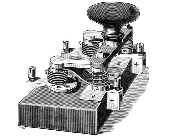
Fig. 26.
Until a larger amount of mileage is actually at work, it is difficult to express an opinion as to which is the cheapest and most efficient method of laying conductors in the streets. The relative cost of two plans tried at Kensington Court—the insulated and the bare cable in a culvert—was given by Mr. Crompton in the following Tables, No. 1 and No. 2, which are taken from a paper read before the Society of Telegraph Engineers and Electricians on April 12th, 1888.
Table No. 1 refers more particularly to what is known as the Callender-Webber system of using bitumen concrete, which is compressed into blocks or cases usually about 6 ft. long, 8 in. by 5½ in. section, having two-inch holes through which the insulated copper cable is led.
The estimates given in Table No. 2 were criticised by Mr. Kapp, who thought that “a more reliable conductor could be obtained by using a high-class lead-covered cable, which might be laid in the ground with the simple protection of a rough tarred plank to cover it.” The cost of digging the trench and running in the cable from the drum was quoted at 3s. a yard, and the total cost, inclusive of £10 for surface boxes, at £155 per 100 yards, instead of £187, as shown by the Table.
Table I.
Cost of Laying 100 Yards of Double Conductor underneath the Footway of a London Street.
Single. No. 16. ⁷⁄₁₆ ¹⁹⁄₁₅ ¹⁹⁄₁₂ ¹⁹⁄₁₀
Area, square inches ·0032 ·0225 ·0773 ·1613 0·25
Area, square millimetres 2·08 14·6 50 104 161·25
Weight per 100 yards run lb. 7½ 53½ 183¼ 392 576
Cost of copper at 7¾ d. £ 0 4 10 1 14 6 5 18 0 12 13 0 18 15 0
Cost of insulation 1 3 2 4 8 6 11 2 0 24 17 0 35 17 0
Total cost of Cables 1 8 0 6 3 0 17 0 0 37 10 0 54 12 0
Casing, bitumen, and cement 5 3 0 5 5 0 8 0 0 12 10 0 12 10 0
Labour, Laying 3 0 0 4 0 0 5 0 0 5 0 0 6 0 0
Trenching and repairing 25 0 0 25 0 0 25 0 0 25 0 0 25 0 0
Surface boxes and connection 5 0 0 7 0 0 10 0 0 10 0 0 10 0 0
Engineer and superintendent 3 0 0 4 0 0 5 0 0 5 0 0 6 0 0
Total £ 42 11 0 51 8 0 70 0 0 95 0 0 114 2 0
Add extra if copper, at 9½ d. 0 1 1 0 8 0 1 7 0 2 17 0 3 5 0
42 12 1 51 16 0 71 7 0 97 17 0 117 7 0
Cost of copper per lb., laid complete 5 13 6 0 19 4 0 7 9 0 5 0 0 4 1
Current in ampères 1·2 8·1 28 58 90
Cost per ampère 35 10 0 6 8 0 2 10 6 1 13 9 1 6 0
³⁷⁄₁₀ Two Sets. ³⁷⁄₁₀ Four Sets. ³⁷⁄₁₀ Six Sets. ³⁷⁄₁₀
Area, square inches 0·5 1·0 2·0 3·0
Area, square millimetres 322 645 1290 1935
Weight per 100 yards run lb. 1153 2306 4612 6918
Total cost of Cables 108 0 0 216 0 0 432 0 0 648 0 0
Casing, bitumen, and cement 16 0 0 22 0 0 40 0 0 55 0 0
Labour, Laying 10 0 0 18 0 0 35 0 0 50 0 0
Trenching and repairing 25 0 0 25 0 0 30 0 0 35 0 0
Surface boxes and connection 10 0 0 10 0 0 10 0 0 10 0 0
Engineer and superintendent 10 0 0 10 0 0 20 0 0 25 0 0
Total 179 0 0 301 0 0 567 0 0 823 0 0
Add extra if copper, at 9½ d. 8 10 0 17 0 0 34 0 0 51 0 0
187 10 0 318 0 0 601 0 0 874 0 0
Cost of copper per lb., laid complete 0 3 3½ 0 2 8¾ 0 2 7¼ 0 2 6¼
Current in ampères 180 360 720 1,080
Cost per ampère 1 1 0 0 17 6 0 16 8 0 16 1
Table II.
Cost of Laying 100 Yards of Double Conductor of Bare Copper carried on Insulators in a Culvert.
Area in square inches 0·25 0·5 1·0
Area in square millimetres 161·25 322·5 645
Weight of copper in lb. per 100 yards 576 1153 2306
Cost of copper at 7¾ d. per lb. £ 18 15 0 37 5 0 74 10 0
Laying 9 0 0 9 12 0 9 12 0
Insulators 0 4 6 0 4 6 0 4 6
6 surface boxes and connections 10 0 0 10 0 0 10 0 0
Culvert, 18 inches × 12 inches, for two lines conductor, 53 8 0 53 8 0 53 8 0
in brickwork and cement, replacing pavement
Engineers and superintendence 6 0 0 10 0 0 10 0 0
Total £ 97 7 6 120 9 6 157 14 6
Extra for copper at 9½ d. per lb. 3 5 0 8 10 0 17 0 0
Total £ 100 12 6 128 19 6 174 14 6
Cost of copper per lb. laid complete 42 d. 27 d. 18·2 d.
Current in ampères 90 180 360
Cost per ampère 1 2 3 0 14 5 0 9 8
Area, square inches 2·0 2·55 3·00
Area, square millimetres 1290 1645 1935
Weight of copper in lb. per 100 yards 4612 6125 6918
Cost of copper at 7¾ d. per lb. 149 0 0 190 0 0 224 0 0
Laying 9 15 0 9 15 0 10 0 0
Insulators 0 4 6 0 4 6 0 4 6
6 surface boxes and connections 10 0 0 10 0 0 10 0 0
Culvert, 18 inches × 12 inches, for two lines conductor, 53 8 0 53 8 0 53 8 0
in brickwork and cement, replacing pavement
Engineers and superintendence 10 0 0 10 0 0 15 0 0
Total 232 7 6 263 7 6 312 12 6
Extra for copper at 9½ d. per lb. 34 0 0 43 10 0 51 0 0
Total 266 7 6 306 7 6 363 12 6
Cost of copper per lb. laid complete 13·8 d. 12 d. 12 6 d.
Current in ampères 720 910 1080
Cost per ampère 0 7 5 0 6 9 0 6 8½
The Vienna Central-station.
The practical success of the Battery Transformer system has been demonstrated at Vienna, where an installation of five thousand lamps in the Opera House and Burg Theatre was maintained for the past year from a distributing station 1,400 yards away. The boilers are fixed in a basement formed by excavating the court-yard of a private house to a depth of 15 feet 6 in. below the street level; the building itself is utilised partly for offices and partly as a large dynamo and engine-room. Each dynamo is designed to give an output of 72 kilowatts or 120 ampères, at 600 volts pressure. The current is led by means of a lead-covered cable underground to the accumulators, which are erected in groups of 52 cells each, so as to give 100 volts to the lamps, with a comfortable margin. The total pressure required to charge the four groups of batteries in series varies from 430 volts at the time the batteries are giving off work, to 480 volts for the short time during which the charge is being completed. During five hours of lighting about two-thirds of the current comes direct from the dynamos; but during this time, for short periods, the demand for current often increases to such an extent that these proportions may be reversed, and the batteries supply two-thirds of the total.
The regulation of groups of batteries placed in series is not a difficult matter, and will be understood by referring to the following diagram, Fig. 27:—
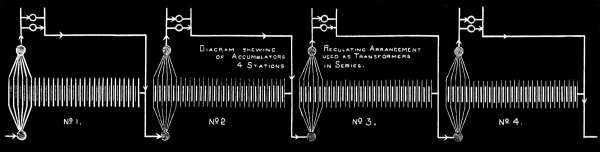
Fig. 27.
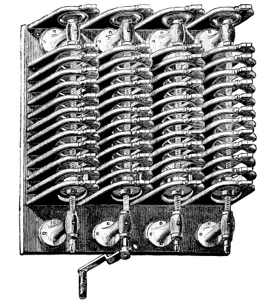
The four battery stations mentioned as arranged in series are represented. The current may be supposed to enter at the right hand corner, passing through the first battery with the lamps parallel to it, and from that battery to the commencement of the next, and so on through the third and fourth, the current being varied at will at the central-station, or kept constant by means of an electrical governor. The potential for each of the four groups of lamps is maintained in the following manner:—In each group one terminal is kept permanently connected to one of the discharge mains and to one of the charging mains; the other terminal can be shifted from cell to cell according to the E. M. F. required in the corresponding lamp circuit by means of a contact regulator. This movable terminal is shown by the bunch of lines at one extremity of each battery group. The rule for charge and discharge is, that the terminal cell at the regulating end of the battery is so arranged that it neither receives nor gives off current, so that there is no loss of energy in the shape of E. M. F. The contact regulator, which was designed by Mr. Crompton for use at Kensington Court, is shown by Fig. 28:—
Fig. 28.
Central-Station.
The ring contacts are arranged in a line in such a manner that a circular contact-piece, made of thin sheets of copper, can be forced through them in turn by means of a central screw spindle. The mains for charge and discharge are attached to the fixed disc contacts on the central screws, and the regulating cells of the battery are coupled to their respective contact rings by sockets at the back of the board.
The difficulty with the battery transformer system is the introduction of 400 to 500 volts into the houses, which would be necessary without the batteries are always fixed in sub-stations from which a low-pressure current, say of 100 volts E. M. F., could only be distributed.
A method has been devised by Mr. Henry Edmunds to obviate this disadvantage. He also uses the high-tension current to charge the batteries, but by means of a distributor, which is automatically worked by the current, each group of cells is charged in turn, when it is entirely cut off from the supply main to the house, through which current is perhaps being taken for lighting purposes. The system is now being adopted by the Cadogan Electricity Supply Company, Chelsea.
Direct-Current Transformers or Dynamotors.
The method of transforming by direct current without the aid of batteries is not practically at work; but, as the advantages are so obvious and its development is only a question of time, a description of the system may not be considered out of place.
The electrical exhibition at Philadelphia in 1884 contained a dynamotor which was exhibited by the Van de Poele Electric-Light Company, but, as far as could be ascertained, was not worked, and, as it was simply described as an induction machine for distributing currents for the use of incandescent and other lights, it attracted little attention.
The advantages of an alternating current transformer system of distribution, Class II., has been put forward in these pages, especially that of simplicity and cheapness. An alternating current dynamo for a given output is cheaper than a direct, and it takes less labour to look after it, because it has no commutator.
An alternating transformer is also an exceedingly simple piece of apparatus. If originally made with due care and kept in a dry place, it never breaks down, as it has no moving parts, and so there is nothing to go wrong.
The alternating system of distribution has, however, some very serious disadvantages. In the first place, it is most important that motors should be driven during the day when the lights are not in use. In the second, batteries cannot be used in an alternating current system, so any immunity from breakdown that they might ensure is wanting; and steam must be kept up all day and all night.
If motors are wanted during the day, so that the load on the engine is nearly constant, batteries are not so valuable, except with a view of preventing a breakdown; but, if batteries cannot be used, the advantage of using motors becomes enormous, as the plant has to be large enough to supply the maximum load, and would otherwise be idle during the day.
In alternating current systems there are two difficulties in the way of using motors. It is difficult to make an alternating current motor that will start, and, if that difficulty is surmounted, it is difficult to make an alternating current motor that will work on varying loads without great waste of power. The question of the efficiency of alternating current motors has never been really practically studied yet; and, until these difficulties are overcome, we must regard alternating current motors as non-existent. Several methods of working alternating current transformers off direct currents by commutating the primary have been proposed at different times; but they all seem to be impracticable, and it seems impossible to get over the difficulties that arise from sparking when it is attempted to break a high-tension circuit.
One of the first methods of distribution over large areas proposed was by means of motors and dynamos combined. For instance, suppose, in order to keep down the size of the leads, 2,000 volts are used in the mains, a motor capable of working with 2,000 volts is put down where the lights are wanted, and this is made to drive a dynamo giving 100 volts and a large current. Instead of having a separate motor and a dynamo connected by a belt or by coupling the spindles together, it is simpler to make one machine with two armatures, or to have only one armature with two circuits on it. One circuit is wound with fine wire and takes the 2,000 volts and tends to turn the armature round. The other circuit is wound with thick wire giving 100 volts and a large current, and tends to stop the armature, thus absorbing the power supplied by the high-pressure circuit. The direct-current transformer or dynamotor is thus a sort of double dynamo, or dynamo and motor combined. If it gets 2,000 volts and 10 ampères, it would, if there were no waste, give 100 volts and 200 ampères; with a waste of 10 per cent., it will give 100 volts and 180 ampères.
In the United States it is usual to place an alternating current motor in each house to be lighted; but the conditions are quite different there, overhead wires being used extensively. In this country this system is not likely to find favour, and local sub-stations will be used, the high pressure, which is always dangerous to life, will thus be kept out of private houses and offices. There is, then, very little difference in the cost of maintenance of alternating current transformers and dynamotors, and the advantages possessed by alternating current transformers in this respect are more than counter-balanced by the use of motors on direct current circuits.
Dynamotors have not come into general use yet because no stations have been started in this country of the size which demands them. No central station with sub-stations is in operation, but there is every reason to expect several will be soon; and it is very necessary to discuss the various methods, not only in use at this moment but coming into use in the immediate future. The dynamotor itself needs no working out, as any maker of direct-current dynamos can, of course, make them. Messrs. Paris and Scott of Norwich showed some in operation at the Newcastle Exhibition in 1887; the most successful type is that recently invented by Mr. Jas. Swinburne, illustrated by Fig. 29. The backward main round primary or motor magnet is shown on the left, and the forward main round the secondary or dynamo magnet on the right, the outside coil round both magnets is the shunt.
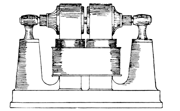
Fig. 29.
The dynamotor may be made with two circuits on one armature as already explained, or it may have two armatures in separate fields, still making up one machine. The first arrangement has two grave disadvantages. There is difficulty about securing perfect insulation between the two circuits, and this leads to chances of danger in the houses. A dynamotor with two circuits on one armature cannot be compounded, that is to say, it cannot be made to give constant electrical pressure on the mains if the number of lamps is varied. A Swinburne double armature machine can be compounded, not only to give constant pressure with a varying load, but to give constant electrical pressure even if both the load and the pressure on the primary circuit vary. This makes a considerable difference in the copper of the primary leads, as in large and complicated districts it is almost impossible to arrange leads, even when working with high electrical pressure and small currents, so that the electrical pressure remains constant, or even nearly so. A very small variation of the pressure on an incandescent lamp makes an enormous difference in the amount of light it gives, and in its duration. It is, therefore, most important that the E. M. F. on the lamps should be kept absolutely constant.
This difficulty is, of course, insurmountable in the case of alternating current transformers. Alternating current transformers cannot be made to compound, and the loss in leads cannot be corrected by them, so that the lamps burn dull at full load.
If secondary batteries are used at the sub-stations, the reduction of pressure might be effected by them. A number would be charged in series and discharged in parallel. This arrangement needs at least two sets of cells, and cells are expensive; and it is difficult to preserve the insulation of cells with such electrical pressure as 2,000 volts. If cells are used for the purpose of equalising the load or as a safety reserve, it is better to charge them by means of a dynamotor.
Installation and Working Cost of Central-Stations.
Until the balance-sheet of some large central-station has been published, it is impossible to do more than surmise what relation the earning power of the generating plant bears to the initial cost. Those central-stations which are working successfully in this country at the present time are either too small for a reliable estimate to be formed, or, as in the case of the Grosvenor Gallery, the space is too cramped for the large amount of machinery which it has been found necessary to add in order to meet the increasing demands for light. In order to obtain an approximate idea of the cost of installing a station capable of maintaining 10,000 lights, the following data (Table III.) given in Mr. Crompton’s paper before the Society of Telegraph Engineers are extremely valuable and will be examined with interest.
Although the figures given are necessarily empirical and open to criticism, the cost with both systems of distribution is approximately the same, and may be taken roughly at £5,860 per 1,000 lights, which amount, according to Professor Forbes, would be reduced to £3,914 per 1,000 lights if the installation was put down according to American practice, and at the initial cost of the Westinghouse alternating current system.
Mr. Crompton also compares the working cost of the two systems (Table IV.).
Table III.
Cost of 10,000-Light, or 600-Kilowatt,[6] Plant.
A.T.—ALTERNATING TRANSFORMER DISTRIBUTION.
Generating station, buildings, chimney shaft, £
water tanks, and general fittings 11,000
Dynamos and exciters—865 kilowatts, including
spare sets, divided as convenient 5,540
Motive power, i.e., engines, boilers, steam and
feed connections, belts, &c., at £8 12 s. per I.H.P. 12,470
500 transformers, i.e., one to every pair of houses, at £15 each 7,500
2,000 yards primary or charging main, exterior
to area of supply, at £308 per 100 yards 6,160
20,000 yards distributing main, 50 mm. sectional
area, at £91 7 s. (see Table I.) 14,270
Regulating gear 500
£ 57,440
B.T.—ACCUMULATOR TRANSFORMER DISTRIBUTION.
Generating station, buildings, chimney stack, £
water tanks, and general fittings 8,000
Dynamos—600 kilowatts, in six sets of 100 kilowatts each 4,800
Motive power, i.e., engines, boilers, steam and
feed connections, &c., at £8 12 s. per I.H.P. 8,600
4 groups of accumulators, in all 240 cells, in
series, at £40 per cell, including stands 9,600
2,000 yards charging main, at £306 17 s. 6 d.
per 100 yards (see Table II.) 6,137
20,000 yards distributing main, 161·25 mm. sectional
area, at £100 12 s. 6 d. (see Table II.) 20,125
Regulating gear 2,500
£ 59,762
Table IV.
Working Expenses and Maintenance of 10,000-Light, or 600-Kilowatt, Plant.
Direct Alternating Transformer System.
Materials— £ s. d. £ s. d.
Coals: 4,380 tons at 17s. 3,723 0 0
” 2,550 ”17s. · ·
Oil, water, and petty stores:
1,500 hours at 7 s. 6 d.
7,250 hours at 1 s. 925 0 0
1,400 hours at 5 s. · ·
Total cost of material 4,648 0 0
Labour—
2 foreman drivers at 45 s.; 6 drivers at 30 s.;
9 firemen at 24 s.; sundry labour
1 foreman driver at 45 s.; 2 drivers at 30 s.;
3 firemen at 24 s.; sundry labour 1,388 8 0
Salaries—
1 chief at £500; 2 assistants at £200 each; 4 clerks at £80 each 1,220 0 0
1 chief at £500; 1 assistant at £200; 4 clerks at £80 each · ·
2,608 8 0
Maintenance of Plant—
Motive power and dynamos: 10 per cent. on £18,010 1,801 0 0
””10 per cent. on £13,400 · ·
Buildings and fittings: 5 per cent. on £11,000 550 0 0
”” 5 per cent. on £8,000 · ·
Transformers: 10 per cent. on £7,500 750 0 0
Accumulators: 15 per cent. on £9,600 · ·
Mains: 7½ per cent. on £20,430 1,532 5 0
”2½ per cent. on £26,262 · ·
Regulating gear: 10 per cent. on £500 50 0 0
”” 10 per cent. on £2,500 · ·
4,683 5 0
11,939 13 0
2,100 units × 365 days = 766,500 units. Cost per unit · · 3·75 d.
Continuous Battery Transformer System.
Materials— £ s. d. £ s. d.
Coals: 4,380 tons at 17s. · ·
” 2,550 ”17s. 2,167 0 0
Oil, water, and petty stores:
1,500 hours at 7 s. 6 d.
7,250 hours at 1 s. · ·
1,400 hours at 5 s. 350 0 0
Total cost of material 2,517 0 0
Labour—
2 foreman drivers at 45 s.; 6 drivers at 30 s.;
9 firemen at 24 s.; sundry labour
1 foreman driver at 45 s.; 2 drivers at 30 s.;
3 firemen at 24 s.; sundry labour 975 0 0
Salaries—
1 chief at £500; 2 assistants at £200 each; 4 clerks at £80 each · ·
1 chief at £500; 1 assistant at £200; 4 clerks at £80 each 1,020 0 0
1,995 0 0
Maintenance of Plant—
Motive power and dynamos: 10 per cent. on £18,010 · ·
””10 per cent. on £13,400 1,340 0 0
Buildings and fittings: 5 per cent. on £11,000 · ·
”” 5 per cent. on £8,000 400 0 0
Transformers: 10 per cent. on £7,500 · ·
Accumulators: 15 per cent. on £9,600 1,440 0 0
Mains: 7½ per cent. on £20,430 · ·
”2½ per cent. on £26,262 656 10 0
Regulating gear: 10 per cent. on £500 · ·
”” 10 per cent. on £2,500 250 0 0
4,086 10 0
8,598 10 0
2,100 units × 365 days = 766,500 units. Cost per unit · · 2·7 d.
With the exception of the amount allowed for depreciation of the accumulators, which time alone can show to be correct, the expenses may be said to be over rather than under-estimated; the 15 per cent. depreciation given in Table IV. is under what has hitherto been found necessary to allow for the renewal of the plates of a secondary battery.
If the mean of the two results in Table IV. are taken, the working cost per Board of Trade Unit will be 3·22d., which shows that with both systems, after making due allowance for interest on capital, directors’ fees, bad debts, and other sundries omitted by Mr. Crompton, there is a probability of a very fair return on the capital expenditure, and the prospect of a handsome dividend for an electric lighting company who can sell electricity at the average price of 7d. per Unit.
The cost of maintaining and working electric lighting plant at private installations is usually much in excess of a supply from a central-station; but where the installation is over 500 lights, the difference is not very great.
The working cost at the Athenæum Club of 387 lamps for the past year is given as follows:—
£ s. d.
Gas for gas-engine 446 7 10
Oil”” 71 3 8
Water ”” 35 0 0
Wages 175 2 1
Sundries 30 3 0
Maintenance of lamps, etc. 98 4 1
Repairs 103 1 1
£ 959 1 9
Average cost of lighting by gas and oil for previous years, for two-thirds number of lights £840.
At the Naval and Military Club, 420 lights cost £821 18s. for the same period, a steam-engine being used instead of a gas-engine.
The annual report of the cost of the electric light at the South Kensington Museum shows that in a larger installation, consisting both of arc and incandescent lamps, the annual cost of the latter is much less than in either of the clubs mentioned. At the Museum there are 860 16 candle-power lamps, working 655½ hours per annum, or 562,387 lamp hours; the total cost for working last year was £386, which includes £66 for repairs of engines, boilers, dynamos, and maintenance of lamps; but rent, interest on capital, depreciation of plant, and management is not included. The light is used only three evenings a week, so that the wages of the attendants are proportionately in excess of what they would be in a central-station.
The cost of arc lighting for street purposes may be estimated from the following tenders. At Taunton the local electric light company offered to extend the lighting of streets from 29 to 60 arc lamps of 1,200 candle-power nominal on the Thomson-Houston system, at the following rate:—
Per annum.
£ s. d.
Burning on average of 6 hours per night each lamp 17 7 6
7 ” ” 18 12 6
8 ” ” 19 17 6
The posts and supports to be provided and fixed by the company, or, if the town council found the same, the company would allow a deduction at the rate of 5 per cent. per annum upon the outlay made by the council. The lamps are usually about 400 feet apart.
The actual cost of operating arc lights on this system is given in the following detailed expenses of a six hours’ run of a 50-light plant for the street lighting of an American city:—
2,600 lb. Ind. nut and slack coal, at $1·30 per ton $1·69
Engineer, one night, at $50·00 per month 1·67
Superintendent or electrician, one night, at $50·00 per month 1·67
Trimmer, one day, at $40·00 per month 1·33
48 pairs of carbons, at $18·50 per month 89
Waste, &c., at $20·00 per year 05
Water rent, at $40·00 per year 11
Half-pint cylinder oil, at 60c. per gallon 04
One pint engine and dynamo oil, at 50c. per gallon 06
One day repairs on machine and lamps, including globes, at $120·00 per year 33
One day taxes on 50-light plant, assessed at $5,000, at 2¼ per cent. 31
One day interest on 50-light plant ($10,000), at 6 per cent. 1·67
Making a total of $9·82
10½ d. or 20·45 cents. per lamp. £15 10 s. per annum.
If, in addition to the 50 street lights, 33 other arc lights are maintained, the total cost is reduced for a six hours’ run to $13·25, or £2 15s. 2d. for the 83 lights, 8d. or 15·96 cents per lamp, £12 3s. 4d. per annum.
Table V. has been calculated by M. Decker, of Nuremburg, and gives the comparative cost of working 150 lamps by electricity and by gas. The gas price (1) is that paid in Paris, namely, 6s. 9d. per 1000 cubic feet; column (2) is the price usually taken commercially, which includes the fixed charges. The price of electricity is given: 1st, when a steam-engine is available; 2nd, when it is necessary to lay down a special engine; 3rd, when a gas-engine is used the gas is charged at a trifle over the price in column (1).
Table V.
Total Cost per Hour and per Lamp.
Legend for Table V.
A = Number of hours’ work per year.
B = Number of hours’ work per day.
C = Steam-engine (existing).
D = Hydraulic Motor.
E = Steam-engine to be erected.
F = Gas engine
G = (1) Gas at 6s. 9d. per 1,000 ft.
H = (2) Gas at 8s. 9d. per 1,000 ft.
A B C D E F G H
Pence. Pence. Pence. Pence. Pence. Pence.
500 1·38 0·485 1·055 1·216 0·418 0·552
800 2·19 0·371 0·780 1·007 0·399 0·513
1,200 3·29 0·314 0·608 0·865 0·380 0·352
3,600 9·87 0·219 0·152 0·352 0·485 0·361 0·465
Arc Lamps.
500 1·38 5·235 4·246 10·459 11·485
800 2·19 3·971 3·089 7·552 9·272
1,200 3·29 3·087 2·441 6·004 7·581
3,600 9·87 2·185 1·510 3·591 5·586
Underground or Overhead Wires.
Apart from the unsightly appearance of overhead wires, there are many reasons why any extended system of supply of electricity should be carried out by underground cables. It is true that there have been no accidents in this country due to electric light wires falling, owing to the care bestowed on their insulation and erection; on account of the heat generated by the passage of the current through the leads no snow can accumulate on them, and therefore they are not subjected to the extra weight which destroyed so many of the telegraph and telephone wires in the last snow storm. Overhead electric light wires are exclusively used by the largest electric-supply company in London, and it is probable that, without further legislation takes place, other companies will shirk the expense of an underground system; and even a more dangerous method of running cables than that which has been condemned in the principal cities of the United States will become not the exception but the rule. In the city of New York the process of conversion of the present overhead to an underground system is a fact about to be accomplished to a very great extent at least, in the near future. Since July, 1887, the Western Union Telegraph Company have occupied the conduits, which have been constructed and laid with some 500 miles of wire; also the Metropolitan Telephone and Telegraph Company have 1000 miles of wire in the subways; and the Edison Illuminating Company, whose conductors were laid in the trench at the time of construction, has more than 1000 miles of underground cable. The plan adopted is to build conduits of section, as in Fig. 30, which shows the subway in course of construction, with man-hole opening and exposed ends of conduits. The single tube at top is for distribution between man-holes, and some wires are shown entering the vault on the right from the service box in the foreground. The conduits are of various types; creosoted wooden tubes are placed in creosoted wooden casings; wrought-iron pipes are sometimes laid in asphaltic concrete with creosoted wooden box; another arrangement is to be of composition blocks on concrete, and cover them with brick—or wrought-iron pipe is lined with cement, and laid in hydraulic cement concrete and cased with creosoted plank. About 85 per cent. of all the conduits have been constructed on this plan, the interior diameter of the pipes being 2½ inches.
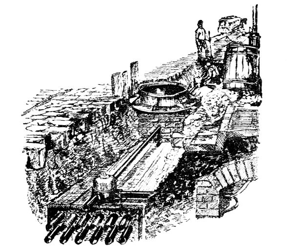
Fig. 30.
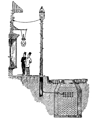
Fig. 31.
Fig. 31 shows how the street arc lighting wires are taken, also a branch for house use, out of the man-holes, which are placed at each street crossing. For the cleaning purposes and for drawing the cable through the conduits, these must be laid practically straight.
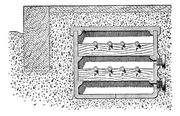
Fig. 32.
Fig. 32 illustrates a method proposed by Mr. Kenneth Mackenzie, which is somewhat similar to the system of conduit which, used at Tours for the past two years, has been found most efficient for the high potential supply mains to the transformers. The troughs would be about 4 ft. long and 15 in. deep, having spigot and socket joints at the ends like ordinary water pipes. Transverse pieces of wood, or preferably slate, would rest upon projections, and would support the mains, and a cover recessed as shown would make the conduit fairly water-tight; drain holes would be provided, and the branches to houses led off through glands in the side of troughs. The American plan is, doubtless, the best, as there is no space for moisture to collect in the conduits; but Mr. Mackenzie’s system is well worth trying, and has the advantage of being much cheaper in first cost.
The Edison plan is to place two solid conductors in a tube which is filled up solid with an insulating material, suitable bends and offsets being supplied, so that the tube containing the two conductors can be buried in the ground like a gas-pipe. The system is very largely used both in the United States and in Continental cities; but it is doubtful whether the protection would suffice in our towns, where the streets are already at the mercy of the gas and water companies, whose workmen, with a single blow of a pick, might perforate the tube, and cause a dangerous short circuit.
The Interests of Gas Companies as to Electric Lighting.
The policy of gas companies with regard to electric light has, with few exceptions, been a state of indifference to the progress of things electric, with contempt for a rival whose opposition is not sufficiently powerful to be appreciated. The chairman of a well-known gas company stated, what is undisputed,—that the introduction of electric arc lights was accompanied by an increased consumption of gas in the immediate neighbourhood where these lights are used; but it is very doubtful whether this will be the case when incandescent lights are generally supplied. The introduction of these lights into any business district would mean the displacement of at least as many burners as there are electric lamps; and this reduction not only means loss of income, but also loss by interest on plant which is not kept at work to the capacity for which it was designed. The question suggests itself, “Are existing gas companies more favourably situated for furnishing electricity than any one else?” There are many reasons in favour of the supposition that the directors of gas companies have at the present time an opportunity of acquiring almost as complete a monopoly of lighting by electricity as they have with gas. As regards central-stations, everything is in their favour; there is generally some spare ground for the machinery, waste heat could be utilised, and a cheap fuel in the shape of coke is ready to hand. They have greater facilities for breaking up streets without danger of troubles arising with the local authorities, and if the Gasworks Clauses Acts, which authorise their existence, tie them down to one illuminant, a very little expenditure would enable them to enlarge their powers. In many towns the shareholders are local men who wish to use the electric light, but cannot favour its introduction because they think it would tend to smaller dividends or lower quotations for their shares; if, however, a scheme was promoted either by the gas company, or, if that was impossible, if the directors interested themselves in a separate electric light undertaking, the security which the gas and water investments command would, no doubt, cause a sufficient number of local subscribers to come forward and make even a small installation a paying concern. The Imperial Continental Gas Association have already taken up the supply of electricity in Vienna, and are likely to extend this new branch of their business to the other cities in which they hold gas concessions; also in the United States the growing opposition of the electric light companies is being seriously discussed, and already several gas companies are installing electric light plants.
It is not at all probable that the scare which caused such a drop in the value of gas shares when the electric light first appeared will be repeated, but the present high price of gas shares cannot be maintained. Kerosene lamps have been for some time a far greater rival to gas than electricity. The cheapening of petroleum, which is now shipped in bulk to this country in tank steamers, will cause the consumption to increase, and enable the oil to be supplied at a price so that it can be used in petroleum-engines, and give a motive power which will be found to be far more economical than the gas-engine. The latest development of petroleum-engines is that shown by Messrs. Priestman at the Royal Agricultural Society’s Show at Nottingham. The engine in external appearance is like the Otto gas-engine, but uses the ordinary “paraffin oil” of commerce, which has a high flashing point. The oil is simply put into a closed tank, and on the top of this, air is forced which drives the petroleum into a chamber heated by the exhaust from the engine, where it is partially vaporised and led into the cylinder with sufficient air to cause it to ignite by means of an electric spark.
The report of the trials with a 5 horse-power engine show that a brake horse-power was obtained for 1·7 lb. of oil, or at 6½d. per gallon for 1·4d. per horse-power per hour; with the Spiel engine the cost is stated to be 0·8d. per horse-power per hour.
Any serious reverse to the gas industry would cause a great pecuniary loss to a large number of investors. The paid-up and borrowed capital devoted to the manufacture and supply of gas in the United Kingdom exceeds £56,000,000, of which above £36,000,000 appertain to the companies and the remainder to the local authorities, whose receipts in respect of their gas undertakings last year exceeded £4,400,000.
The corporation of Bradford, who are owners of the gasworks, have wisely foreseen that it is better to keep the electric light in their own hands, and are now about to erect a central-station, and will lay underground wires; the amount sanctioned for this preliminary installation is £20,000.
The Lucigen Light.
A few remarks on this method of obtaining light from the combustion of crude petroleum may be added, as the light has been put forward as a cheaper and better substitute for the electric arc. The Lucigen light is produced by burning creosote oil, tar oil, or other heavy hydro-carbons, by means of compressed air in a special form of lamp, and consists of a cylinder at the side of which a steam donkey compressing pump is mounted, or in a more recent form known as the Wells’ light, no separate air compressor is used, but, instead, the pressure is obtained from the water mains or from a small force pump. The cost is stated to be 3d. per hour for 2,500 candle-power, requiring three gallons of oil per hour, but is in reality at the present time double this owing to the price of the oil, which, under the most advantageous circumstances, costs on average 2d. per gallon. At the Forth Bridge these lights have been found of use in illuminating open spaces, but have not supplanted the electric arc lights which are universally employed for the lighting of the works and the interior of the shops. The disadvantages are the noise, the oil shower which pervades the vicinity of the light causing timber staging to be highly inflammable, and the difficulty of preventing water from entering the burner, a few drops sufficing to extinguish the light. The use of the Lucigen light is, therefore, very limited, and it is probable that, in situations where shadows from the arc light are found to be objectionable, large incandescent electric lamps, which are supplied up to 1,500 candle-power, would meet the case; or, failing these, petroleum could be burnt in lamps similar to those used in lighthouses with greater safety, and at not much increased cost, than the compressed-air system.