CLASS I. Supply by Secondary Generators or Transformers.
Reading edition
The problem of electric lighting from central-stations is comparatively easy if an area can be obtained immediately surrounding, and within a short distance of, the station, with a right of way for laying down the electric mains direct. This happy state of affairs has not yet been attained, consequently the generating station has more often to be in an out-of-the-way corner of the district to be lighted, and it would be financially impossible to use low-tension currents with correspondingly large mains. The difficulty has been overcome in several ways by the use of high-tension currents in the mains, and has led to the adoption of secondary generators or transformers of electricity, which by induction supply a current of low potential in the house-service. The first to make this plan a practical success was Mr. Goulard, to whom the honour of the introduction is due, although his claims as the first inventor have been recently upset by the decision of the Courts.
The relative economy of the supply of electricity by the use of a transformer is clearly shown by the following diagram, Fig. 7. A, B, and C give proportionately the area of cross section of the total mass of copper necessary to supply 5000 16 candle-power glow lamps situated at a mean distance of 4000 feet from the dynamo. A refers to the Edison “three-wire” system, working at a potential or electrical pressure of 200 volts with a fall of potential or loss of energy in the distributing feeders of 10 per cent., average distance from dynamo 4000 feet—the usual conditions on which this system is worked. B shows the size of conductor required for the same work in an installation based on the transformer system, potential 1000 volts, allowing 2·5 per cent. loss in the supply mains—only one-fourth as much as in the direct Edison system at the same average distance from dynamo. If this loss were increased to 10 per cent., and made equal to that in the direct system, viz. 10 per cent., the size of the conductor would be that shown at C.
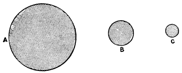
Fig. 7.
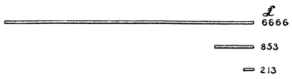
Fig. 8.
The graphic diagram, Fig. 8, demonstrates what the relative cost would be with each of the three conditions just named.
Mr. Goulard’s first practical application of the secondary generator in this country was the lighting of the Underground Railway Stations, in 1883, from Edgware Road to High Street, the generating dynamo being fixed at the former place. These experiments, which were made by Mr. Kenneth Mackenzie, attracted considerable attention at the time, but it was not until the report of the jurors to the Turin International Exhibition in 1885 was published that companies were formed to instal the Goulard system for lighting an extensive district.
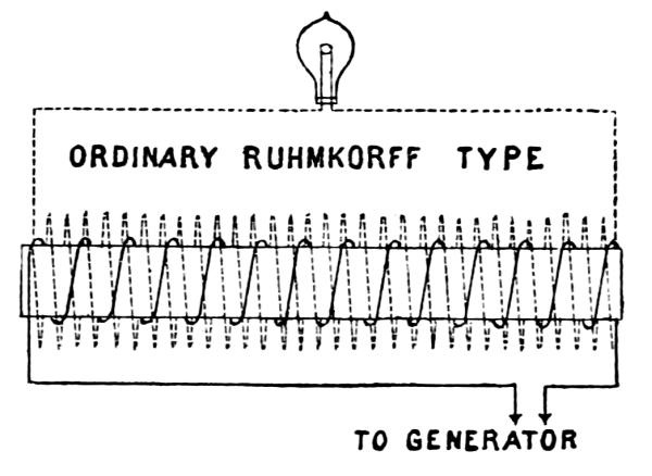
Fig. 9.
The principle underlying all transformers is that of the induction coil invented by Ruhmkorff in 1842, but described by Faraday in his “Experimental Researches,” published in 1831-2.
Fig. 9 is a diagram of the ordinary induction coil; on a central core is wound a short length of thick wire called the primary, and again over this is wound a greater length of fine insulated copper wire which forms the secondary coil. On sending a low-pressure current from the generator round the thick wire, a much smaller high-tension current is induced in the secondary. A contact breaker is employed to make and break the current, or, as in the early instruments, a commutator may be used to produce the alternations. When used as a transformer the action is reversed, that is, a high-tension current is passed through the primary coil, which is composed of a wire of small sectional area, the high-pressure main connected to the dynamo also being small as compared with the distributing cable leading from the transformer, which, acting as a step-down induction coil, converts the electricity into a safe working pressure.
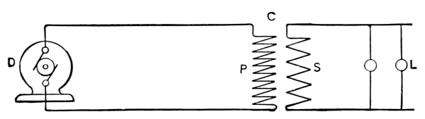
Fig. 9a.
Fig. 9 a shows the arrangement of the two separate and complete circuits. D is the dynamo, P the primary coil, S the secondary, and L the lamps arranged in parallel.
It is hardly necessary to go into the technical details of the various improvements which have led up to the modern type of transformers; they are summarised by Mr. Kapp into two classes:—
I. Core transformers, one core and two sets of coils.
II. Shell transformers, two cores and one set of coils.
No. I. are those in which the copper coils are spread over the surface of the iron core enveloping the latter more or less completely; and No. II. in which the core is spread over the surface of the copper coils forming a shell over the winding.
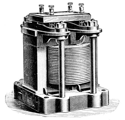
Fig. 10.
The original Goulard and Gibbs secondary generator was of the core transformer type, it had an open magnetic circuit and cores which could more or less be inserted into the coils so as to regulate the electro-motive force of the secondary circuit. The transformers were constructed with a number of copper disks or washers; these were placed alternately primary and secondary in a vertical frame, through the centre of which an iron core was fixed, consisting of a bundle of straight iron wires. The core was movable in the coil in the manner of the well-known induction coils, and thereby the electro-motive force of the secondary current could be adjusted. In their latest design the coils are circular in plan and rectangular in section and are surrounded by groups of U-shaped soft iron stampings slipped over from both sides and held together by two circular cast-iron plates with a central bolt. The magnetic lines of force pass through the core, in at one end and out at the other, and are then more or less disseminated through space; it will thus be seen that the path of the lines lies partly in iron and partly in air, and, since air has about seven hundred times more magnetic resistance than iron, it is evident that the number of lines created with a given current must be considerably smaller than would be the case if the path of the lines contained iron only. This constitutes the improvement in the Zippernowsky-Deri-Blathy system of transformer, which has coils similar to the Goulard, but with the iron of the core applied in the form of a ring-shaped shell, surrounding both coils completely. This arrangement can best be described by comparing it to a Gramme armature, in which the copper and the iron have changed places. Imagine what is usually the core in an armature replaced by the primary and secondary coils, and, instead of the winding of insulated copper wire, wind iron wire around the coils, and one of these transformers is the result. In consequence of the lower magnetic resistance of the Class II. transformer, as compared to that of Class I., the electrical output obtainable with equal weights of copper and iron appears to be considerably greater in the former apparatus. Professor Feraris, of Turin, has published some of the results of comparative experiments made with Classes I. and II. and finds that the coefficient of induction is 3·6 times as great with the latter as with the former. There are many varieties of transformers in the market which closely resemble each other; one of the most practical is that designed by Kapp and Snell, of which Fig. 10 is an illustration. U-shaped stampings form the shell and the cores are laid in the double trough. The cover of these troughs is formed from the metal removed from the interior of the stampings, and the whole is held together in a cast-iron frame so arranged as to allow air to circulate through the core and round the coils. The price of these transformers is about £4 per indicated horse-power, and the efficiency under the best conditions, namely, with full load, is, according to Professor Ayrton, as high as 96 per cent., and when it is doing one quarter of the full work 89 per cent.
Application of Transformers.
The installation at the Grosvenor Gallery, London, may be taken to illustrate Class I. or the practical working of distribution by means of transformers.
Fig. 11 represents the arrangement of primary and secondary circuits.
An alternating current is sent through the main L L¹, which is a closed circuit, and a small portion is drawn off wherever there is a secondary generator or transformer T; these instruments are placed in parallel between the conductors in the same manner as a glow lamp; neither main can be called positive or negative, as the current flows backwards and forwards many times in a second. The house wires M M are joined to the secondary circuits, and are quite distinct from the main, which they do not even touch, although sufficiently near to receive an induced current alternating the same as the primary, but of a much lower electro-motive force.
Fig. 11.
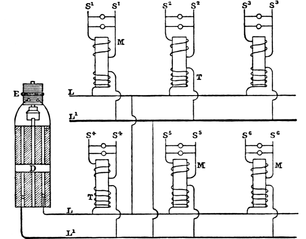
D, alternating current dynamo; M M, secondary conductors;
E, continuous current dynamo for exciting; T T, transformers;
L L¹, main primary conductors; S¹ S² S³ S⁴ S⁵ S⁶, lamps in parallel.
The Goulard transformers were used at first, but have been superseded by others designed by Mr. Ferranti; they are of the No. 2 kind, or shell type, and have a core of hoop-iron, on which the two coils are wound; the hoop-iron is then bent over, and the ends joined so as to enclose the coils. The machinery is fixed in a basement excavated under the Grosvenor Gallery; the foundations are of massive concrete, in which stone supports for the engines and dynamos are embedded; the concrete does not touch the walls of the building, but a space of about 1 foot is left, which is filled in with clay; and by this simple plan all vibration of the machinery is isolated from the building. The power is obtained from two horizontal high-pressure engines, each of 600 indicated horse-power, in addition to the original two horizontal high-pressure non-condensing engines, each of 35 nominal horse-power, running at a speed of 55 revolutions per minute, which is maintained constant by means of a governor directly attached to the expansion slide-valve. The four engines drive on to a countershaft, which is cut up into lengths; each section is coupled to a dynamo and exciter by means of a conical friction-disk clutch; this permits of either length being started or stopped without interfering with the other. The speed of each engine is checked by means of a liquid speed-indicator, designed by the author. Two Ferranti alternating current dynamos, each capable of maintaining ten thousand lamps, are driven direct, one dynamo by each length of shafting: they are excited by two continuous current machines, the circuits from which are joined to a regulating apparatus, which by altering resistance keeps the electro-motive force of the large machines proportional to the number of lamps which are to be maintained. At present hand regulation is employed, but it is proposed to use automatic regulation, which will increase the life of the lamps, as they are severely tried by the variation of the current, which is more noticeable than in continuous current installations. The current from the machines is at a potential of 2400 volts, and that from the transformers is 100 volts. The primary wire which carries this high electro-motive force does not enter the houses, as the transformers are, as a rule, fixed in the cellars, and from them the house branch is led in the form of a cable of fine wires, having a total diameter of 7/16 inch; the lamps, which are placed in parallel across this cable, are attached to single No. 18 or No. 20 B. W. G. wires in the usual manner. When first established, the transformers presented an element of danger, in that they, in common with all induction coils, were also condensers, and therefore a dangerous shock might be given to any one touching some unguarded portion of the lighting system. This has been prevented by the simple plan of connecting one of the terminals of every secondary circuit to earth, a method which, however, is not to be recommended, as it throws an additional strain on the insulation of the primary circuit; in fact, by earthing the secondary the insulation is practically reduced to one-half. A safety device should be inserted, which would come into operation on any leakage from primary to secondary, and immediately cut out the transformer.
The primary-current conductor is led overhead, and still remains an objectionable feature of the system, although the original trouble with the neighbouring telephones and telegraphs has been overcome. The primary circuit is a small carefully insulated cable of high conductivity copper wire, nineteen strands of No. 15 B. W. G. It weighs about 1¾ ton per mile, and is suspended, where it crosses the streets, on a steel bearer whose tensile strength is 1⅕ ton. It is so arranged according to the droop of the cable that the strain of the bearer never exceeds 225 lbs., which means that the factor of safety is nearly 12 to 1. Double cut-outs or safety fuses, in many instances of the author’s design, are placed on each pole of the primary, at the point where it enters the house, so that, in the case of an excess current, the mica-foils would fuse, and all connection between that house and the supply main would cease.
Much credit is due to M. Goulard, who, in spite of great opposition to the use of his transformer system, initiated the Grosvenor Gallery installation three years ago. It has developed into not only the largest and most important central-station in Europe, but, as regards the transformer system, it supplies more lights than any in the United States. The original company has been taken over by the London Electric Supply Corporation, who are putting down plant capable of maintaining 30,000 lights, and are erecting another station at Deptford for 200,000 lights, which will be distributed by means of district transformers from mains, which it is proposed to run from Deptford through the Thames Tunnel and the Underground Railways. The electric current is supplied by meter at the price of 7¼d. per Board of Trade Unit, a price for light equal to gas at about 4s. 2d. per 1000 cubic feet.
The Eastbourne station is also on the transformer system. An alternating current dynamo, by Ellwell Parker, maintains a pressure in the primary circuit of 2000 volts, which is reduced by means of a Lowrie Hall transformer to a working pressure of 100 volts. There is a special arrangement for maintaining a constant electro-motive force in the mains, independent of the number of lights in use. The mains are carried underground, and have so far given no trouble as regards the insulation of the high-tension current which passes through them. The Eastbourne company commenced by lighting the parade only with arc lamps, but now supply the incandescent light to all parts of the town, and enjoy the unique position of having obtained power from the corporation to run the mains in the streets prior to the passing of the Act of 1882. Another small station has been successfully worked for the last six years at Brighton; the group system was originally adopted, the lamps, both arc and incandescent, being placed in series or multiple series; the high-tension current is led through overhead wires in a very similar manner to the installation at Temesvar, Hungary, which is described at page 58, as an example of multiple series lighting. The extensions at Brighton are to be carried out on the transformer plan, which will necessitate the running of separate circuits, the intention of the company, however, being to gradually convert its whole system of supply to the transformer system. The Brighton Company has regularly paid dividends to its shareholders since its formation.
On the Continent the Goulard transformer is largely employed.
An important installation at Tours of 3500 lamps has been for some time successfully working. Another at Tivoli has some additional points of interest, in that the natural power of a waterfall is applied to generate electricity. Two turbines constructed by Escher Wyss, of Zurich, having an available head of 29·75 feet, give 80 horse-power each, which is employed to drive two Siemens alternating current dynamos, separately excited by two small continuous current machines. Two distinct circuits of chromo-bronze naked wire, 3·7 millimetres in diameter, are run overhead, in the same manner as telegraph wires, through the town for a total length of about nineteen miles. The street lamps are fixed alternately on each circuit, so that one-half can be extinguished at a late hour without interfering with the others, or having to turn out individual lamps. The number of lamps used in the streets is two hundred glow lamps of 50 candle-power; also one hundred and twenty glow lamps of 16 candle-power for the illumination of the narrower streets. Arc lamps are also employed, as well as a large reflector lamp, the rays from which are turned on the Temples of Vesta and Sibilla. A house-to-house system is also being established, and the company which has put up the work proposes to utilise the falls of Tivoli in order to transmit 2000 horse-power for lighting purposes in Rome.
The firm of Ganz, of Budapest, who are the manufacturers of the Zippernowsky-Deri-Blathy system of transformers, have a similar installation completed in order to light a portion of Lucerne. The water power of Thorenburg 3·1 miles off, works the turbines, which drive two self-exciting alternating current dynamos of the Ganz type, similar to those shown at the Vienna Exhibition in 1884. The primary current of 38 ampères, at an electro-motive force of 1800 volts, is led by four uncovered wires, each six millimetres in diameter, to the first station, which is 2·4 kilometres distant; here 1500 watts are taken off, and at 2·3 kilometres further 7000 watts are utilised in two of the hotels at Lucerne. A large installation on the same system has been put down in Rome, and several Continental cities are adopting this method of supplying electric light by small overhead wires. An advantage claimed by the Zippernowsky system is the method of keeping the strength of the magnetic field of the dynamos in accordance with the external demand for current. The regulating apparatus employed consists of a small transformer, the primary coil of which is traversed by the whole, or by a proportionate part, of the main circuit, while the secondary coil is inserted into the exciting circuit. Thus, if the main current increases, the exciting current induced in the two armature coils of the dynamo is reinforced by the inductive action of the regulating transformer; and the field of the dynamo is strengthened when more current is required. The opposite takes place when, through the extinction of lamps on the external circuit, the demand for current becomes less. In an experiment made with the transformers, which supply some five hundred electric lamps for the Teatro dal Verone and adjoining houses at Milan from the central electrical station three-quarters of a mile away, the main current was often found to vary from one ampère to thirty-five ampères; it was stated that no variation in the service pressure could be detected, and the lamps burnt with equal brightness whatever the number in use. In the experiments at the Teatro dal Verone each transformer worked its own independent circuit of lamps; but, if the conditions of the different circuits were alike, they could be coupled up together in any manner desired, and thus a group of transformers could become a centre of distribution.
The Westinghouse System.
The alternating current system of the Westinghouse Company has come to the front in the United States with extraordinary rapidity, and, although it is not three years since the first plant was erected, at the present time over 190,000 incandescent lamps are operated from a number of central-stations. The fundamental principles of the Goulard system have been retained in the Westinghouse converter; but the manner in which these principles are applied has been greatly modified, while most of the details have undergone a radical change at the hands of the engineers and electricians whose researches have been utilised by the Westinghouse Company. The form of converter as now designed consists of a number of thin sheet-iron plates, shaped like the letter E, they are slipped alternately from opposite directions over the primary and secondary coils, which are disposed side by side; the inductive core is, therefore, composed of a mass of detached plates insulated from each other by paper, and forming a discontinuous magnetic circuit. In order to protect the converter from mechanical injury as well as dampness, and also to avoid the possibility of contact with wires carrying currents of high potential, it is enclosed in a cast-iron case or box, made in two parts and adapted to be secured to any convenient support. Fig. 12 is a transverse vertical section of such a converter box, with the converter in position. The terminals of the primary coil, P, of the converter are led into the compartment D¹, and the terminals of the secondary coil into D². The terminals are secured to bolts or couplings, f f, mounted upon insulating plates, e¹ and e². Fusible mica-foils, g, and switch plates, h and i, with plugs k, are provided for protecting and disconnecting the circuits. The open front of the compartments D¹ and D² are closed by glass plates, T, which permit inspection of the connections without entering the box. The converter box occupies little space, and may be placed in any convenient situation in or about the premises to be lighted, much the same as a gas-meter. The practice where overhead conductors are employed, is to mount the converter box on a pole in the vicinity of the premises to be lighted, as shown by Fig. 13, and thus it is only necessary to lead the secondary or low potential wires into the building, the high potential wires remaining in an accessible position upon the pole. Fig. 14 is a view of North Street, Pittsfield, Massachusetts, engraved from a photograph, and shows a very neat form of tubular pole with its converter box on top. This arrangement is used throughout the city, and is a great improvement on the ordinary form of telegraph poles which so greatly disfigure American cities, and are really the most objectionable feature of the overhead wire system.
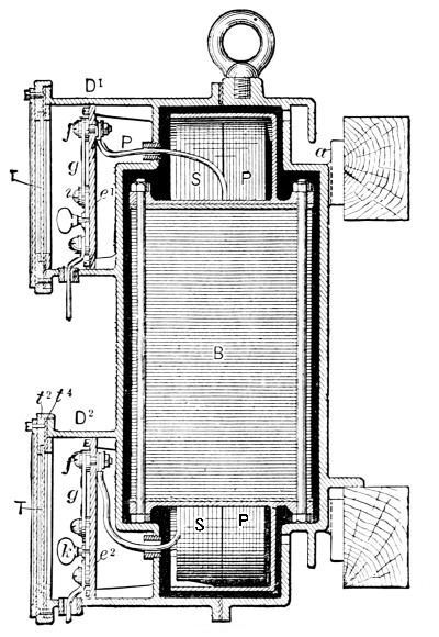
Fig. 12.
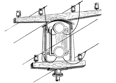
Fig. 13.
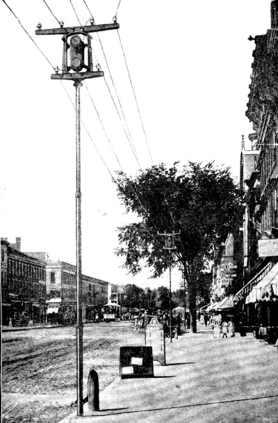
Fig. 14.
The potential ordinarily employed in the main circuits of the Westinghouse installations is about 1000 volts, and that in the lamp circuits 50 volts, the ratio of conversion, therefore, being as 20 to 1; the dynamos are manufactured, as a rule, in three sizes, No. 1 for 650, 16 candle-power lamps; Nos. 2 and 3 for respectively 1300 and 2500 lamps. The converters are also made in three ordinary sizes to supply 20, 30, and 40 lamps of 16 candle-power each. A 40-light converter contains about 85 pounds of iron and 25 pounds of copper, so that the total weight of metal is less than 3 pounds per lamp; the electrical efficiency of the converter is said to exceed 95 per cent. when the potential is reduced from 1000 volts in the primary to 50 in the secondary. “It is claimed that the trifling loss of energy in conversion from high to low potential at the point of consumption is made up for by gain at other points, especially in the increased efficiency of the lamps, so that an alternating current plant may be counted on to give 10-16 candle-power lamps per indicated horse-power, as against 7 with the direct system;” the comparative gain is doubtful, but by using 50 instead of 100 volts the life of the lamps is increased, the former having a much stronger filament and consequently a longer life.
Electric Motors.
Having slightly diverged from the original lines by describing a system which is at present not introduced into Europe, a few remarks on the subject of electric motors may not be inappropriate, as they are almost universally worked in the United States, from the installation which supplies electric light. There is a considerable profit to the electric company if electric power is taken in the district, the wires conveying the lighting current are thus economically employed during the day. In the diagram, Fig. 15, which represents a district at Boston, the curve on the right principally represents the demand for power which takes place between the hours of 8 a.m. and 3 p.m. A circular was addressed to all the leading electric companies in America a short time ago, asking if they supplied power as well as light, also for what purposes it was used.
Answers were received from 56 companies, who stated that the motors were employed for:—driving ventilator fans, collar-and-cuff machines, printing-presses, various apparatus in repair-shops, sewing-machines, coffee-mills, gun-shop tools, sausage-machines, elevators, lathes, pumps, saws, ice-cream freezers, organ-bellows, and washing-machines. The size of motors varied from one-eighth to 15 horse-power; 26 companies have supplied motors from arc light circuits, 14 from arc and incandescent, and 16 from incandescent circuits alone. The motors are principally owned by the subscribers, and are charged for at a rate varying from £3 to £15 per horse-power per month. The motor business is still in its infancy, but is cited to show how Electric Power can supplant the steam-engine, especially for those purposes in which the power required is small and complete control is desirable.
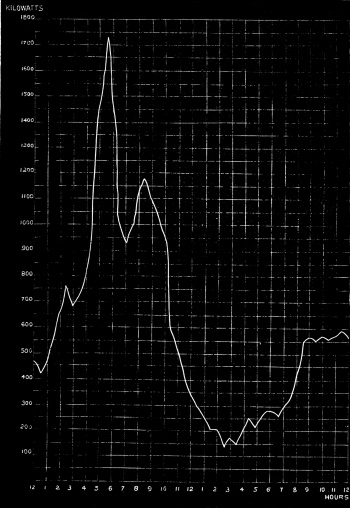
Fig. 15.